Vantage CNM Centralized Network Management User’s Guide Version 3.0 11/2007 Edition 1 www.zyxel.
About This User's Guide About This User's Guide " The screens in Vantage CNM vary by device type and firmware version. The examples in this User’s Guide use one of the most comprehensive examples of each screen, not every variation for each device type and firmware version. If you are unable to find a specific screen or field in this User’s Guide, please see the User’s Guide for the device for more information.
About This User's Guide The Technical Writing Team, ZyXEL Communications Corp., 6 Innovation Road II, Science-Based Industrial Park, Hsinchu, 300, Taiwan. E-mail: techwriters@zyxel.com.
Document Conventions Document Conventions Warnings and Notes These are how warnings and notes are shown in this User’s Guide. 1 " Warnings tell you about things that could harm you or your device. Notes tell you other important information (for example, other things you may need to configure or helpful tips) or recommendations. Syntax Conventions • Vantage CNM may be referred to as “Vantage CNM” or the “product” in this User’s Guide.
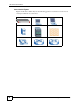
Document Conventions Icons Used in Figures Figures in this User’s Guide may use the following generic icons. Device icons are not an exact representations of your devices.
Contents Overview Contents Overview Introducing Vantage CNM .......................................................................................................... 31 Introduction ............................................................................................................................ 33 GUI Introduction ........................................................................................................................ 35 Device Operation ........................................
Contents Overview About Vantage CNM ................................................................................................................ 321 Account Management .......................................................................................................... 323 Group ....................................................................................................................................... 325 Account .........................................................................
About This User's Guide .......................................................................................................... 3 Document Conventions............................................................................................................ 5 Contents Overview ................................................................................................................... 7 Chapter 1 Introducing Vantage CNM ..............................................................................
5.3 WAN General (ZyNOS ZyWALL) ......................................................................................... 67 5.3.1 WAN1 (ZyNOS ZyWALL with one WAN port) ............................................................ 69 5.3.2 WAN1 and WAN2 (ZyNOS ZyWALL with two WAN ports) ......................................... 77 5.3.3 Dial Backup (ZyNOS ZyWALL) .................................................................................. 85 5.3.4 Advanced Modem Setup (ZyNOS ZyWALL) ....................
6.9 IDP Signatures .................................................................................................................. 152 6.9.1 Attack Types ............................................................................................................. 152 6.9.2 Intrusion Severity ..................................................................................................... 154 6.9.3 Signature Actions ......................................................................................
Chapter 8 Device Log............................................................................................................................. 209 8.1 Device Log ......................................................................................................................... 209 Chapter 9 Device Configuration Management..................................................................................... 213 9.1 Synchronization .....................................................................
11.3 Signature Status ............................................................................................................... 245 Part III: VPN Management ................................................................... 247 Chapter 12 VPN Community.................................................................................................................... 249 12.1 VPN Community ..............................................................................................................
17.1.3 Alarm States ........................................................................................................... 272 17.1.4 Unresolved Alarms ................................................................................................. 272 17.1.5 Responded Alarm .................................................................................................. 273 Part V: Log & Report............................................................................
21.5 Log Setting ...................................................................................................................... 305 21.6 VRPT Management ......................................................................................................... 306 21.6.1 General .................................................................................................................. 306 21.6.2 Add/Edit VRPT Management ...........................................................................
Part VIII: Troubleshooting ................................................................... 333 Chapter 29 Troubleshooting.................................................................................................................... 335 29.1 Vantage CNM Access and Login ..................................................................................... 335 29.2 Device Management ........................................................................................................ 336 29.
Figure 1 Vantage CNM Application ......................................................................................................... 31 Figure 2 Main Screen ............................................................................................................................. 35 Figure 3 Device Window: Topology ....................................................................................................... 37 Figure 4 Folder Right-Click Options ............................................
Figure 39 Device Operation > Device Configuration > Network > WAN > WAN1/2 - PPTP (ZyNOS ZyWALL with two WAN ports) ..................................................................................................... 83 Figure 40 Device Operation > Device Configuration > Network > WAN > Dial Backup (ZyNOS ZyWALL) 86 Figure 41 Device Operation > Device Configuration > Network > WAN > Dial Backup > Advanced (ZyNOS ZyWALL) .......................................................................................
Figure 74 Device Operation > Device Configuration > Security > IDP > Signature (Query View) ........ 157 Figure 75 Device Operation > Device Configuration > Security > Signature Update ........................... 160 Figure 76 Device Operation > Device Configuration > Security > Content Filter > General ................ 162 Figure 77 Device Operation > Device Configuration > Security > Content Filter > Policy ....................
Figure 110 Device Operation > Configuration Management > Configuration File Management > Schedule List (Device) ................................................................................................................ 221 Figure 111 Device Operation > Configuration Management > Configuration File Management > Schedule List (Folder) ................................................................................................................
Figure 143 VPN Management > VPN Monitor > By Community > Show Detail ................................... 258 Figure 144 VPN Management > VPN Monitor > By Community > Show Detail > Diagnostic .............. 259 Figure 145 VPN Management > VPN Monitor > By Community > Show Detail > Diagnostic > Logs .. 260 Figure 146 VPN Management > VPN Monitor > By Device > VPN Tunnel Status ...............................
Figure 180 CNM System Setting > Maintenance > System ................................................................. 313 Figure 181 CNM System Setting > Maintenance > System > Backup ................................................. 314 Figure 182 CNM System Setting > Device Owner ............................................................................... 315 Figure 183 CNM System setting > Device Owner > Add/Edit ..............................................................
Figure 223 Network Number and Host ID ............................................................................................ 368 Figure 224 Subnetting Example: Before Subnetting ............................................................................ 370 Figure 225 Subnetting Example: After Subnetting ............................................................................... 371 Figure 226 IP Address Conflicts: Case A ...........................................................................
Vantage CNM User’s Guide
Table 1 Menu Bar Icon Description ........................................................................................................ 36 Table 2 Title Bar Icon Description .......................................................................................................... 37 Table 3 Device Window: Topology ......................................................................................................... 38 Table 4 Device Window: Icons .......................................................
Table 37 Wireless Card: No Access 802.1x + Static WEP .................................................................. 106 Table 38 Wireless Card: No Access 802.1x + No WEP ....................................................................... 106 Table 39 Device Operation > Device Configuration > Network > Wireless Card > MAC Filter ............ 107 Table 40 Device Operation > Device Configuration > Security > Firewall > Default Rule ....................
Table 75 Device Operation > Device Configuration > Security > X Auth > RADIUS ........................... 183 Table 76 Device Operation > Device Configuration > Advanced > NAT > NAT Overview ................... 186 Table 77 Device Operation > Device Configuration > Advanced > NAT > Port Fowarding ................. 188 Table 78 Device Operation > Device Configuration > Advanced > NAT > Address Mapping ..............
Table 107 Device Operation > Configuration Management > Building Block > Configuration BB > Add/Edit/ Save as ...................................................................................................................... 230 Table 108 Device Operation > Configuration Management > Building Block > Component BB .......... 232 Table 109 Device Operation > Configuration Management > Building Block > Component BB > Add/Edit/ Save as ........................................................................
Table 144 Log & Report > Operation Report > Signature Profile Backup & Restore Report > Restore Report ........................................................................................................................ 289 Table 145 LOG & Report > CNM Logs ............................................................................................... 292 Table 146 CNM System Setting > Configuration > Servers > Configuration .......................................
Vantage CNM User’s Guide
CHAPTER 1 Introducing Vantage CNM This chapter introduces the main applications and features of Vantage CNM. It also introduces the ways you can manage Vantage CNM. 1.1 Overview Vantage Centralized Network Management (“Vantage CNM”) helps network administrators monitor and manage a distributed network of ZyXEL network devices. A typical application is shown in the following example.
Chapter 1 Introducing Vantage CNM 1.2 Ways to Manage Vantage CNM Use the web configurator to access and manage Vantage CNM. See the Quick Start Guide for instructions to access the web configurator and this User’s Guide for more information about the screens. 1.3 Suggestions for Using Vantage CNM Do the following things regularly to make Vantage CNM more secure and to manage Vantage CNM more effectively. • Change the root password.
P ART I Introduction Introducing Vantage CNM (31) GUI Introduction (35) 33
CHAPTER 2 GUI Introduction See the Quick Start Guide for instructions about installing, setting up, and accessing Vantage CNM. This chapter introduces the Vantage CNM main screen. Figure 2 Main Screen 2 1 3 4 5 The main screen consists of three main parts and are numbered in the sequence you typically follow to configure a device.
Chapter 2 GUI Introduction " For security reasons, Vantage CNM automatically times out after fifteen minutes of inactivity. Log in again if this happens. Each part is discussed in more detail in the following sections. 2.1 Menu Bar The following table describes the icons in the menu bar. Table 1 Menu Bar Icon Description ICON DESCRIPTION Click this icon to display the navigation links to screens that allow you to configure, manage firmware or license for a selected device.
Chapter 2 GUI Introduction 2.2 Title Bar The following table describes the icons in the title bar. Table 2 Title Bar Icon Description ICON DESCRIPTION This icon displays with a hi to the current login user. Click this icon to display the dashboard in the configuration window. Click this icon to open a window to display real-time Vantage CNM system logs. 2.
Chapter 2 GUI Introduction The following table describes the labels in the Device window. Table 3 Device Window: Topology LABEL DESCRIPTION Topology Click Topology to display device groups in a tree structure. Search Click Search to look for device(s). There are a couple icons in the device window that perform additional functions related to views. Table 4 Device Window: Icons Icon Description Click this icon to set how often the OTV tree refreshes. Click this icon to refresh the OTV tree. 2.3.1.
Chapter 2 GUI Introduction Table 5 Device Window: Folder Icons (continued) Icon Status Description Off_ Alarm_Pending-Closed This is a closed folder, which contains one or some offline devices. Some devices with an alarm while some with pending tasks. Off_ Alarm_Pending-Open This is a opened folder, which contains one or some offline devices. Some devices with an alarm while some with pending tasks. You can right-click on a folder to see the following menu items.
Chapter 2 GUI Introduction 4 A new folder icon displays. 2.3.1.1.2 Delete a Folder Deleting a folder also deletes all the associated device(s). Follow the steps below to delete a group. 1 In the device window, click Topology. 2 Right-click on a folder and click Delete Folder. 3 A warning screen displays. Click OK to delete. Click Cancel to close this screen without deleting the selected folder. Figure 7 Device Window: Topology: Delete Folder Warning 2.3.1.1.
Chapter 2 GUI Introduction Table 6 Device Window: Device Icons (continued) Icon Description Not Yet Acquired This is a device never registered itself to Vantage CNM since it is added in the device window. On_Alarm This is a device turned on with an alarm. Off_Alarm This is a device turned off with an alarm. On_Pending This is a device turned on with pending tasks. Off_Pending This is a device turned off with pending tasks.
Chapter 2 GUI Introduction Figure 11 Device Window: Topology: Add/Edit Device (ZyNOS) Figure 12 Device Window: Topology: Add/Edit Device (ZLD) The following table describes the labels in this screen. Table 7 Configuration Screen: Device List LABEL DESCRIPTION LAN MAC (Hex) Enter the LAN MAC address of the device (without colons) in this field. Vantage CNM uses the MAC address to identify the device, so make sure it is entered correctly.
Chapter 2 GUI Introduction Table 7 Configuration Screen: Device List (continued) LABEL DESCRIPTION Firmware Version This field is only available for a ZyNOS device. Select the firmware version the device is currently using. The pull-down menu lists only supported firmware versions. Select Unknown if you don’t know the device’s firmware version or you cannot find your device’s current firmware version from the list. Note: Not all ZyXEL devices can work with Vantage CNM.
Chapter 2 GUI Introduction 4 After clicking Apply and a new device icon displays. 2.3.1.2.2 Delete a Device Follow the steps below to delete a group. 1 In the device window, click Topology. 2 Right-click on a device and click Delete Device. 3 A warning screen displays. Click OK to delete. Click Cancel to close this screen without deleting the selected device. Figure 13 Device Window: Topology: Delete Device Warning 2.3.1.2.
Chapter 2 GUI Introduction Figure 15 Device Window: Topology: Delete Device Warning 3 The device’s web configurator appears via a HTTP or HTTPS connection. You can change the device login setting by editing a device. Refer to Figure 11 on page 42. 2.3.2 Device Search Use the Search function in the device window to look for device(s). 1 In the device window, click Search. Figure 16 Device Window: Search 2 Specify the search criteria (such as the device type, device status, etc.) and click Search.
Chapter 2 GUI Introduction Table 8 Navigation Panel: Menu Summary - Device Operation DEVICE OPERATION ZYNOS-BASED DEVICE ZLD-BASED DEVICE PRESTIGE Device Configuration Load or Save BB General System Tim Setting Network LAN WAN DMZ WLAN Wireless Card Port Roles Security Firewall VPN Anti-Virus Anti-Spam IDP Signature Update Content Filter X Auth Advanced NAT Static Route DNS Remote Management Device Log Configuration Management Synchronization Configuration File Management Signature Profile Management Bu
Chapter 2 GUI Introduction Table 9 Navigation Panel: Menu Summary - Others CNM SYSTEM SETTING ACCOUNT MANAGEMENT Servers User Access Notification Log Setting VRPT Management Certificate Management Maintenance Device Owner Upgrade License About Group Account The following table describes the links in the navigation panel. Table 10 Navigation Panel Links LINK DESCRIPTION Device Operation Device Configuration This link takes you to a screen where you can configure general device information.
Chapter 2 GUI Introduction Table 10 Navigation Panel Links (continued) LINK DESCRIPTION VRPT This function is available if any Vantage Report (VRPT) server is configured on the selected device. This link takes you to a screen where you can see reports generated by an associated VRPT server. CNM System Setting Configuration This link takes you to a screen where you can configure Vantage CNM settings.
Chapter 2 GUI Introduction 1 Click CNM System Setting in the menu bar. 2 Click Configuration > Certificate Management in the navigation panel. 3 Click Create CSR. The following screen appears. Figure 17 CNM System Setting > Configuration > Certificate Management > Create CSR 4 Type the IP address of the Vantage CNM server in the Common Name field. This is the IP address you use to log in (http://your IP address:8080/vantage). The value localhost cannot be used in the Common Name field.
Chapter 2 GUI Introduction Figure 19 CNM System Setting > Configuration > Certificate Management > Import Certificate 8 Enter the signed certificate file path and click Apply. 9 Restart the Vantage CNM server. 10 Use the IP address and log into the Vantage CNM server. 11 In Internet Explorer 7.0, click View Certificates when the following screen appears. Figure 20 Pop-up Message in Internet Explorer 7.0 12 Certificate screen appears.
P ART II Device Operation " " This menu only appear if you select a device. For ZLD-based device, this menu appear when the device status is on. The menus and screens may vary depending on the device model you select. See Table 8 on page 46 for the device model and the corresponding firmware version CNM supports.
CHAPTER 3 Load or Save Building Blocks (BB) " These menus only appear if you select a ZyNOS-based or a prestige device. 3.1 Load or Save BB Use this menu item to load building blocks to the selected device or to create building blocks from the current configuration of the selected device. This menu item appears if a device is selected. See Chapter 34 on page 356 for more information about building blocks.
Chapter 3 Load or Save Building Blocks (BB) Click the Load a BB icon to load a building block to the selected device. The following popup screen appears. Figure 22 Device Operation > Device Configuration > Load or Save BB > Load a BB Select the building block you want to load to the selected device, and click Apply. Click the Save as a BB icon to save the current configuration of the selected device as a building block. The following pop-up screen appears.
CHAPTER 4 Device General Settings This section configures device general settings. " These menus only appear if you select a ZyNOS-based or a prestige device. For ZLD-based device, these menus appear when the device status is on. 4.0.1 System Use this screen to set the password, system name, domain name, idle timeout, and DNS servers for the device. Please see the device’s User’s Guide for more information about any of these screens or fields.
Chapter 4 Device General Settings Table 11 Device Operation > Device Configuration > General > System (continued) FIELD DESCRIPTION Domain Name The Domain Name entry is what is propagated to the DHCP clients on the LAN side of the target device. If you leave this blank, the domain name obtained by the device via DHCP from the ISP is used. Administrator Inactivity Timer Set how long a management session can remain idle before it expires. After it expires, you have to log back into the device.
Chapter 4 Device General Settings Table 12 Device Operation > Device Configuration > General > Time Setting (continued) LABEL DESCRIPTION Daylight Savings Daylight saving is a period from late spring to early fall when many countries set their clocks ahead of normal local time by one hour to give more daytime light in the evening. Select this option if you use Daylight Saving Time. Start Date Configure the day and time when Daylight Saving Time starts if you selected Daylight Savings.
Chapter 4 Device General Settings 58 Vantage CNM User’s Guide
CHAPTER 5 Device Network Settings The screens explained network settings such as LAN, WAN, wireless card. The menus and screens may vary for different ZyXEL products. For example, click Device Configuration > Network Interface for ZLD-based device’s network settings. This document uses the ZyNOS ZyWALL settings for each screen description. For ZLD-based settings, please see device’s User’s Guide for the detailed information. An example is shown next.
Chapter 5 Device Network Settings Figure 27 Device Operation > Device Configuration > Network > LAN > LAN The following table describes the fields in this screen. Table 13 Device Operation > Device Configuration > LAN > LAN 60 LABEL DESCRIPTION DHCP Mode DHCP (Dynamic Host Configuration Protocol, RFC 2131 and RFC 2132) allows individual clients (workstations) to obtain TCP/IP configuration at startup from a server. Unless you are instructed by your ISP, leave this field set to Server.
Chapter 5 Device Network Settings Table 13 Device Operation > Device Configuration > LAN > LAN (continued) LABEL DESCRIPTION DHCP WINS Server 1, 2 Type the IP address of the WINS (Windows Internet Naming Service) server that you want to send to the DHCP clients. The WINS server keeps a mapping table of the computer names on your network and the IP addresses that they are currently using. Pool Size This field specifies the size, or count of the IP address pool.
Chapter 5 Device Network Settings Table 13 Device Operation > Device Configuration > LAN > LAN (continued) LABEL DESCRIPTION Allow between LAN and WAN2 Select this check box to forward NetBIOS packets from the LAN to WAN port 2 and from WAN port 2 to the LAN. If your firewall is enabled with the default policy set to block WAN port 2 to LAN traffic, you also need to enable the default WAN port 2 to LAN firewall rule that forwards NetBIOS traffic.
Chapter 5 Device Network Settings Figure 28 Device Operation > Device Configuration > Network > LAN > LAN (Prestige) The following table describes the fields in this screen. Table 14 Device Operation > Device Configuration > Network > LAN > LAN (Prestige) LABEL DESCRIPTION DHCP Mode DHCP (Dynamic Host Configuration Protocol, RFC 2131 and RFC 2132) allows individual clients (computers) to obtain TCP/IP configuration at startup from a server. Select None if you do not want to configure DNS servers.
Chapter 5 Device Network Settings Table 14 Device Operation > Device Configuration > Network > LAN > LAN (Prestige) LABEL DESCRIPTION TCP/IP IP Address Type the IP address of the device in dotted decimal notation. IP Subnet Mask The subnet mask specifies the network number portion of an IP address. Unless you are implementing subnetting, use the “natural” subnet mask, which is usually 255.255.255.0.
Chapter 5 Device Network Settings Use this screen to assign IP addresses to specific individual computers on the LAN based on their MAC addresses. To open this screen, click Device Operation in the menu bar, and click Device Configuration > Network > LAN > Static DHCP in the navigation panel. Figure 29 Device Operation > Device Configuration > Network > LAN > Static DHCP The following table describes the fields in this screen.
Chapter 5 Device Network Settings Figure 30 Device Operation > Device Configuration > Network > LAN > IP Alias The following table describes the fields in this screen Table 16 Device Operation > Device Configuration > Network > LAN > IP Alias 66 LABEL DESCRIPTION IP Alias 1,2 Select the check box to configure another network for the device. IP Address Enter the IP address of the device in dotted decimal notation.
Chapter 5 Device Network Settings 5.3 WAN General (ZyNOS ZyWALL) This section gives configuration information on the fields displayed in this screen. To open this screen, click Device Operation in the menu bar, and click Device Configuration > Network > WAN > General in the navigation panel.
Chapter 5 Device Network Settings The following table describes the fields in this screen. Table 17 Device Operation > Device Configuration > Network > WAN > General (ZyNOS ZyWALL) LABEL DESCRIPTION WAN Priority WAN2 Priority Traffic Redirect Dial Backup The default WAN connection is "1' as your broadband connection via the WAN port should always be your preferred method of accessing the WAN.
Chapter 5 Device Network Settings Table 17 Device Operation > Device Configuration > Network > WAN > General (ZyNOS ZyWALL) (continued) LABEL DESCRIPTION Allow between WAN2 and DMZ Select this check box to forward NetBIOS packets from the WAN2 port to the DMZ port and from the DMZ port to WAN2. Clear this check box to block all NetBIOS packets going from the WAN2 port to the DMZ port and from DMZ port to WAN2.
Chapter 5 Device Network Settings 5.3.1.1 Ethernet Encapsulation The following table describes the labels in the Ethernet encapsulation screen. Table 18 Device Operation > Device Configuration > Network > WAN > ISP (Ethernet) – ZyNOS ZyWALL (one WAN port) LABEL DESCRIPTION Encapsulation You must choose the Ethernet option when the WAN port is used as a regular Ethernet.
Chapter 5 Device Network Settings Table 18 Device Operation > Device Configuration > Network > WAN > ISP (Ethernet) – ZyNOS ZyWALL (one WAN port) (continued) LABEL DESCRIPTION Apply Click Apply to save your changes back to the device. Reset Click Reset to begin configuring this screen afresh. 5.3.1.2 PPPoE Encapsulation The device supports PPPoE (Point-to-Point Protocol over Ethernet).
Chapter 5 Device Network Settings Figure 34 Device Operation > Device Configuration > Network > WAN > WAN1-PPPoE (ZyNOS ZyWALL with one WAN port) The following table describes the labels in the PPPoE screen. Table 19 Device Operation > Device Configuration > Network > WAN > ISP (PPPoE) – ZyNOS ZyWALL (one WAN port) LABEL DESCRIPTION WAN:ISP Encapsulation The PPPoE choice is for a dial-up connection using PPPoE. The router supports PPPoE (Point-to-Point Protocol over Ethernet).
Chapter 5 Device Network Settings Table 19 Device Operation > Device Configuration > Network > WAN > ISP (PPPoE) – ZyNOS ZyWALL (one WAN port) (continued) LABEL DESCRIPTION Service Name Type the PPPoE service name provided to you. PPPoE uses a service name to identify and reach the PPPoE server. User Name Type the user name given to you by your ISP. Password Type the password associated with the User Name above.
Chapter 5 Device Network Settings Table 19 Device Operation > Device Configuration > Network > WAN > ISP (PPPoE) – ZyNOS ZyWALL (one WAN port) (continued) LABEL DESCRIPTION Multicast Choose None (default), IGMP-V1 or IGMP-V2. IGMP (Internet Group Multicast Protocol) is a network-layer protocol used to establish membership in a Multicast group - it is not used to carry user data. IGMP version 2 (RFC 2236) is an improvement over version 1 (RFC 1112) but IGMP version 1 is still in wide use.
Chapter 5 Device Network Settings Figure 36 Device Operation > Device Configuration > Network > WAN > WAN1 - PPTP (ZyNOS ZyWALL with one WAN port) The following table describes the labels in the PPTP screen.
Chapter 5 Device Network Settings Table 20 Device Operation > Device Configuration > Network > WAN > ISP (PPTP) – ZyNOS ZyWALL (one WAN port) (continued) LABEL DESCRIPTION PPTP User Name Type the user name given to you by your ISP. Password Type the password associated with the User Name above. Retype to confirm Password Type your password again to make sure that you have entered it correctly. Nailed-up Connection Select Nailed-Up Connection if you do not want the connection to time out.
Chapter 5 Device Network Settings Table 20 Device Operation > Device Configuration > Network > WAN > ISP (PPTP) – ZyNOS ZyWALL (one WAN port) (continued) LABEL DESCRIPTION RIP Version The RIP Version field controls the format and the broadcasting method of the RIP packets that the device sends (it recognizes both formats when receiving). Choose RIP-1, RIP-2B or RIP-2M. RIP-1 is universally supported; but RIP-2 carries more information.
Chapter 5 Device Network Settings Figure 37 Device Operation > Device Configuration > Network > WAN > WAN1/2 (ZyNOS ZyWALL with two WAN ports) The following table describes the labels in this screen. Table 21 Device Operation > Device Configuration > Network > WAN > WAN1/2 (ZyNOS ZyWALL with two WAN ports) LABEL DESCRIPTION ISP Parameters for Internet Access 78 Encapsulation You must choose the Ethernet option when the WAN port is used as a regular Ethernet.
Chapter 5 Device Network Settings Table 21 Device Operation > Device Configuration > Network > WAN > WAN1/2 (ZyNOS ZyWALL with two WAN ports) (continued) LABEL DESCRIPTION Telia Login Server (Telia Login only) Type the domain name of the Telia login server, for example login1.telia.com. Relogin Every(mins) (Telia Login only) The Telia server logs the Vantage CNM out if the Vantage CNM does not log in periodically.
Chapter 5 Device Network Settings 5.3.2.2 PPPoE Encapsulation PPPoE (Point-to-Point Protocol over Ethernet) is an IETF standard (RFC 2516) specifying how a personal computer (PC) interacts with a broadband modem (DSL, cable, wireless, etc.) connection. The PPPoE option is for a dial-up connection using PPPoE. For the service provider, PPPoE offers an access and authentication method that works with existing access control systems (for example RADIUS).
Chapter 5 Device Network Settings The following table describes the labels in this screen. Table 22 Device Operation > Device Configuration > Network > WAN > WAN1/2 - PPPoE (ZyNOS ZyWALL with two WAN ports) LABEL DESCRIPTION ISP Parameters for Internet Access Encapsulation The PPPoE choice is for a dial-up connection using PPPoE. The router supports PPPoE (Point-to-Point Protocol over Ethernet).
Chapter 5 Device Network Settings Table 22 Device Operation > Device Configuration > Network > WAN > WAN1/2 - PPPoE (ZyNOS ZyWALL with two WAN ports) (continued) LABEL DESCRIPTION RIP Direction RIP (Routing Information Protocol) allows a router to exchange routing information with other routers. The RIP Direction field controls the sending and receiving of RIP packets. Choose Both, None, In Only or Out Only. When set to Both or Out Only, the Vantage CNM will broadcast its routing table periodically.
Chapter 5 Device Network Settings Figure 39 Device Operation > Device Configuration > Network > WAN > WAN1/2 - PPTP (ZyNOS ZyWALL with two WAN ports) The following table describes the labels in this screen.
Chapter 5 Device Network Settings Table 23 Device Operation > Device Configuration > Network > WAN > WAN1/2 - PPTP (ZyNOS ZyWALL with two WAN ports) (continued) LABEL DESCRIPTION PPTP User Name Type the user name given to you by your ISP. Password Type the password associated with the user name above. Retype to confirm Password Type your password again to make sure that you have entered is correctly. Nailed-up Connection Select this if you do not want the connection to time out.
Chapter 5 Device Network Settings Table 23 Device Operation > Device Configuration > Network > WAN > WAN1/2 - PPTP (ZyNOS ZyWALL with two WAN ports) (continued) LABEL DESCRIPTION RIP Version The RIP Version field controls the format and the broadcasting method of the RIP packets that the device sends (it recognizes both formats when receiving). Choose RIP-1, RIP-2B or RIP-2M. RIP-1 is universally supported; but RIP-2 carries more information.
Chapter 5 Device Network Settings Figure 40 Device Operation > Device Configuration > Network > WAN > Dial Backup (ZyNOS ZyWALL) The following table describes the labels in this screen. Table 24 Device Operation > Device Configuration > Network > WAN > Dial Backup (ZyNOS ZyWALL) LABEL DESCRIPTION Enable Dial Backup Select this check box to turn on dial backup. Basic Settings 86 User Name Type the user name assigned by your ISP. Password Type the password assigned by your ISP.
Chapter 5 Device Network Settings Table 24 Device Operation > Device Configuration > Network > WAN > Dial Backup (ZyNOS ZyWALL) (continued) LABEL DESCRIPTION Primary/Secondary Phone Number Type the first (primary) phone number from the ISP for this remote node. If the Primary Phone number is busy or does not answer, the device dials the Secondary Phone number if available. Some areas require dialing the pound sign # before the phone number for local calls.
Chapter 5 Device Network Settings 5.3.4.1.2 Response Strings The response strings tell the device the tags, or labels, immediately preceding the various call parameters sent from the WAN device. The response strings have not been standardized; please consult the documentation of your WAN device to find the correct tags. Click the Advanced button in the Advanced Modem Setup in the Dial Backup screen to display the Dial Backup Advanced screen shown next.
Chapter 5 Device Network Settings Table 25 Device Operation > Device Configuration > Network > WAN > Dial Backup > Advanced (ZyNOS ZyWALL) (continued) LABEL DESCRIPTION Drop DTR When Hang Up Select this check box to have the device drop the DTR (Data Terminal Ready) signal after the "AT Command String: Drop" is sent out. EXAMPLE AT Response Strings CLID Type the keyword that precedes the CLID (Calling Line Identification) in the AT response string.
Chapter 5 Device Network Settings Figure 42 Device Operation > Device Configuration > Network > WAN > Dial Backup > Edit (ZyNOS ZyWALL) The following table describes the fields in this screen. Table 26 Device Operation > Device Configuration > Network > WAN > Dial Backup > Edit – ZyNOS ZyWALL 90 LABEL DESCRIPTION Get IP Address Automatically from Remote Server Type the login name assigned by your ISP for this remote node.
Chapter 5 Device Network Settings Table 26 Device Operation > Device Configuration > Network > WAN > Dial Backup > Edit – ZyNOS ZyWALL (continued) LABEL DESCRIPTION Enable RIP Select this check box to turn on RIP (Routing Information Protocol), which allows a router to exchange routing information with other routers. RIP Direction RIP (Routing Information Protocol, RFC1058 and RFC 1389) allows a router to exchange routing information with other routers.
Chapter 5 Device Network Settings Figure 43 Device Operation > Device Configuration > Network > WAN > Setup (Prestige) The following table describes the fields in this screen. Table 27 Device Operation > Device Configuration > Network > WAN > Setup (Prestige) 92 LABEL DESCRIPTION Name Enter the name of your Internet Service Provider, for example, MyISP. This information is for identification purposes only.
Chapter 5 Device Network Settings Table 27 Device Operation > Device Configuration > Network > WAN > Setup (Prestige) LABEL DESCRIPTION ATM QoS Type Select CBR (Constant Bit Rate) to specify fixed (always-on) bandwidth for voice or data traffic. Select UBR (Unspecified Bit Rate) for applications that are non-time sensitive, such as e-mail. Select VBR (Variable Bit Rate) for bursty traffic and bandwidth sharing with other applications.
Chapter 5 Device Network Settings Table 27 Device Operation > Device Configuration > Network > WAN > Setup (Prestige) LABEL DESCRIPTION Max Idle Timeout (Appears when you use PPPoA and PPPoE encapsulation) Specify an idle time-out in the Max Idle Timeout field when you select Connect on Demand. The default setting is 0, which means the Internet session will not timeout. Zero Configuration Select this if you want the device to automatically try to configure the Internet connection.
Chapter 5 Device Network Settings Figure 44 Device Operation > Device Configuration > Network > WAN > Backup (Prestige) The following table describes the fields in this screen. Table 28 Device Operation > Device Configuration > Network > WAN > Backup (Prestige) LABEL DESCRIPTION Backup Type Select the method that the device uses to check the DSL connection. Select DSL Link to have the device check if the connection to the DSLAM is up.
Chapter 5 Device Network Settings Table 28 Device Operation > Device Configuration > Network > WAN > Backup (Prestige) LABEL DESCRIPTION Recovery Interval When the device is using a lower priority connection (usually a WAN backup connection), it periodically checks to whether or not it can use a higher priority connection. Type the number of seconds (30 recommended) for the device to wait between checks. Allow more time if your destination IP address handles lots of traffic.
Chapter 5 Device Network Settings 5.3.8 Advanced WAN Backup (Prestige) Use this screen to edit your device’s advanced WAN backup settings. To open this screen, click WAN > Backup and the Advanced button. Figure 45 Device Operation > Device Configuration > Network > WAN > Backup > Advanced (Prestige) The following table describes the fields in this screen.
Chapter 5 Device Network Settings Table 29 Device Operation > Device Configuration > Network > WAN Backup > Advanced (Prestige) (continued) LABEL DESCRIPTION Primary/ Secondary Phone Number Type the first (primary) phone number from the ISP for this remote node. If the primary phone number is busy or does not answer, your device dials the secondary phone number if available. Some areas require dialing the pound sign # before the phone number for local calls.
Chapter 5 Device Network Settings Table 29 Device Operation > Device Configuration > Network > WAN Backup > Advanced (Prestige) (continued) LABEL DESCRIPTION Nailed-Up Connection Select Nailed-Up Connection when you want your connection up all the time. The device will try to bring up the connection automatically if it is disconnected. Connect on Demand Select Connect on Demand when you don't want the connection up all the time and specify an idle time-out in the Max Idle Timeout field.
Chapter 5 Device Network Settings Figure 46 Device Operation > Device Configuration > Network > Wireless Card > Wireless Card The following table describes the fields in this screen. Table 30 Device Operation > Device Configuration > Network > Wireless Card > Wireless Card 100 LABEL DESCRIPTION Enable Wireless LAN You should configure some wireless security when you enable the wireless LAN. Select the check box to enable the wireless LAN.
Chapter 5 Device Network Settings Table 30 Device Operation > Device Configuration > Network > Wireless Card > Wireless Card (continued) LABEL DESCRIPTION Fragmentation Threshold This is the threshold (number of bytes) for the fragmentation boundary for directed messages. It is the maximum data fragment size that can be sent. Select the check box to change the default value and enter a value between 256 and 2432. Security Select one of the security settings. No Security Static WEP WPA-PSK WPA 802.
Chapter 5 Device Network Settings Figure 47 Device Operation > Device Configuration > Network > Wireless Card > Wireless Card (Advanced Wireless Security Settings) 102 Vantage CNM User’s Guide
Chapter 5 Device Network Settings The following table describes the fields in these settings. Table 31 Wireless Card: Static WEP LABEL DESCRIPTION Security Select Static WEP from the drop-down list. WEP Encryption WEP (Wired Equivalent Privacy) provides data encryption to prevent unauthorized wireless stations from accessing data transmitted over the wireless network. Select 64-bit WEP or 128-bit WEP to enable data encryption.
Chapter 5 Device Network Settings Table 33 Wireless Card: WPA LABEL DESCRIPTION Security Select WPA from the drop-down list. ReAuthentication Timer (Seconds) Specify how often wireless stations have to resend user names and passwords in order to stay connected. Enter a time interval between 10 and 65535 seconds. If wireless station authentication is done using a RADIUS server, the reauthentication timer on the RADIUS server has priority.
Chapter 5 Device Network Settings Table 35 Wireless Card: 802.1x + Static WEP LABEL DESCRIPTION Security Select 802.1x + Static WEP from the drop-down list. WEP Encryption WEP (Wired Equivalent Privacy) provides data encryption to prevent unauthorized wireless stations from accessing data transmitted over the wireless network. Select 64-bit WEP or 128-bit WEP to enable data encryption.
Chapter 5 Device Network Settings Table 36 Wireless Card: 802.1x + No WEP (continued) LABEL DESCRIPTION Idle Timeout (Seconds) The Vantage CNM automatically disconnects a wireless station from the wireless network after a period of inactivity. The wireless station needs to send the username and password again before it can use the wireless network again. Some wireless clients may prompt users for a username and password; other clients may use saved login credentials.
Chapter 5 Device Network Settings " Be careful not to list your computer’s MAC address and set the Action field to Deny Association when managing the device via a wireless connection. This would lock you out. Figure 48 Device Operation > Device Configuration > Network > Wireless Card > MAC Filter The following table describes the fields in this screen.
Chapter 5 Device Network Settings 108 Vantage CNM User’s Guide
CHAPTER 6 Device Security Settings The screens explained device security settings such as firewall, VPN, anti-virus, anti-spam, IDP, signature update, content filter and X-auth. The menus and screens may vary for different ZyXEL products. For example, click Device Operation in the menu bar and then click Device Configuration > VPN > IPSec VPN in the navigation panel for ZLD-based device’s network settings. This document uses the ZyNOS ZyWALL settings for each screen description.
Chapter 6 Device Security Settings Figure 50 Device Operation > Device Configuration > Security > Firewall > Default Rule The following table describes the labels in this screen. Table 40 Device Operation > Device Configuration > Security > Firewall > Default Rule LABEL DESCRIPTION Default Rule Setup 110 Enable Firewall Select this check box to activate the firewall. The device performs access control and protects against Denial of Service (DoS) attacks when the firewall is activated.
Chapter 6 Device Security Settings Table 40 Device Operation > Device Configuration > Security > Firewall > Default Rule LABEL DESCRIPTION From, To Set the firewall’s default actions based on the direction of travel of packets. Here are some example descriptions of the directions of travel. From LAN To LAN means packets traveling from a computer on one LAN subnet to a computer on another LAN subnet on the LAN interface of the device or the device itself.
Chapter 6 Device Security Settings Figure 51 Device Operation > Device Configuration > Security > Firewall > Rule Summary The following table describes the labels in this screen. Table 41 Device Operation > Device Configuration > Security > Firewall > Rule Summary LABEL DESCRIPTION Direction Summary Firewall rules are grouped based on the direction of travel of packets to which they apply. Select a direction from the drop-down list box.
Chapter 6 Device Security Settings Table 41 Device Operation > Device Configuration > Security > Firewall > Rule Summary LABEL DESCRIPTION Rule Summary The following fields summarize the rules you have created that apply to traffic traveling in the selected packet direction. The firewall rules that you configure (summarized below) take priority over the general firewall action settings above. Select an ACL hyperlink to edit that ACL rule. # This is your firewall rule number.
Chapter 6 Device Security Settings Figure 52 Device Operation > Device Configuration > Security > Firewall > Rule Summary > Edit 114 Vantage CNM User’s Guide
Chapter 6 Device Security Settings The following table describes the labels in this screen. Table 42 Device Operation > Device Configuration > Security > Firewall > Rule Summary > Add/Edit LABEL DESCRIPTION Rule Name Enter a descriptive name of up to 31 printable ASCII characters (except Extended ASCII characters) for the firewall rule. Spaces are allowed. Active Select this to turn this rule on. Clear this to turn this rule off.
Chapter 6 Device Security Settings Table 42 Device Operation > Device Configuration > Security > Firewall > Rule Summary > Add/Edit (continued) LABEL DESCRIPTION Action for Matched Packets Use the drop-down list box to select what the firewall is to do with packets that match this rule. Select Drop to silently discard the packets without sending a TCP reset packet or an ICMP destination-unreachable message to the sender.
Chapter 6 Device Security Settings The following table describes the labels in this screen. Table 43 Device Operation > Device Configuration > Security > Firewall > Anti-Probing LABEL DESCRIPTION Respond to PING on Select the interfaces on which you want the device to reply to incoming Ping requests. Do not respond to requests for unauthorized services. Select this option to prevent hackers from finding the device by probing for unused ports.
Chapter 6 Device Security Settings The following table describes the labels in this screen. Table 44 Device Operation > Device Configuration > Security > Firewall > Threshold 118 LABEL DESCRIPTION Disable DoS Attack Protection on Select the interface(s) (or VPN tunnels) for which you want the device to not use the Denial of Service protection thresholds. This disables DoS protection on the selected interface (or all VPN tunnels).
Chapter 6 Device Security Settings 6.1.6 Service Click Device Operation in the menu bar and then click Device Configuration > Security > Firewall > Service in the navigation panel to open the screen as shown next. Use this screen to configure custom services for use in firewall rules or view the services that are predefined in the device. Figure 55 Device Operation > Device Configuration > Security > Firewall > Service The following table describes the labels in this screen.
Chapter 6 Device Security Settings Figure 56 Device Operation > Device Configuration > Security > Firewall > Service > Add/ Edit The following table describes the labels in this screen. Table 46 Device Operation > Device Configuration > Security > Firewall > Service > Add/ Edit LABEL DESCRIPTION Service Name Enter a descriptive name of up to 31 printable ASCII characters (except Extended ASCII characters) for the custom service. You cannot use the left parentheses “(“. Spaces are allowed.
Chapter 6 Device Security Settings There are two sets of VPN screens, VPN version 1.0 and VPN version 1.1. The version depends on the device’s type and firmware version. 6.3 IPSec High Availability IPSec high availability (also known as VPN high availability) allows you to use a redundant (backup) VPN connection to another WAN interface on the remote IPSec router if the primary (regular) VPN connection goes down.
Chapter 6 Device Security Settings Figure 58 Device Operation > Device Configuration > Security > VPN > VPN Rules (IKE) The following table describes the labels in this screen. Table 47 Device Operation > Device Configuration > Security > VPN > VPN Rules LABEL Description # This is the VPN policy index number. Name This field displays the identification name for this VPN policy. Local IP Address This field displays the IP address(es) of the network behind the device.
Chapter 6 Device Security Settings Figure 59 Device Operation > Device Configuration > Security > VPN > VPN Rules (IKE) > Gateway Policy Add/Edit Vantage CNM User’s Guide 123
Chapter 6 Device Security Settings The following table describes the labels in this screen. Table 48 Device Operation > Device Configuration > Security > VPN > VPN Rules (IKE) > Gateway Policy Add/Edit LABEL DESCRIPTION Property NAT Traversal Select this check box to enable NAT traversal. NAT traversal allows you to set up a VPN connection when there are NAT routers between the two IPSec routers. Note: The remote IPSec router must also have NAT traversal enabled.
Chapter 6 Device Security Settings Table 48 Device Operation > Device Configuration > Security > VPN > VPN Rules (IKE) > Gateway Policy Add/Edit LABEL DESCRIPTION Remote Gateway Address Type the WAN IP address or the domain name (up to 31 characters) of the IPSec router with which you're making the VPN connection. Set this field to 0.0.0.0 if the remote IPSec router has a dynamic WAN IP address. In order to have more than one active rule with the Remote Gateway Address field set to 0.0.0.
Chapter 6 Device Security Settings Table 48 Device Operation > Device Configuration > Security > VPN > VPN Rules (IKE) > Gateway Policy Add/Edit 126 LABEL DESCRIPTION Local ID Type Select IP to identify this device by its IP address. Select DNS to identify this device by a domain name. Select E-mail to identify this device by an e-mail address. You do not configure the local ID type and content when you set Authentication Key to Certificate. The device takes them from the certificate you select.
Chapter 6 Device Security Settings Table 48 Device Operation > Device Configuration > Security > VPN > VPN Rules (IKE) > Gateway Policy Add/Edit LABEL DESCRIPTION Content The configuration of the peer content depends on the peer ID type. Do the following when you set Authentication Key to Pre-shared Key. • For IP, type the IP address of the computer with which you will make the VPN connection. If you configure this field to 0.0.0.
Chapter 6 Device Security Settings Table 48 Device Operation > Device Configuration > Security > VPN > VPN Rules (IKE) > Gateway Policy Add/Edit LABEL DESCRIPTION Password Enter the corresponding password for the above user name. The password can be up to 31 case-sensitive ASCII characters, but spaces are not allowed. IKE Proposal Negotiation Mode Select Main or Aggressive from the drop-down list box. Multiple SAs connecting through a secure gateway must have the same negotiation mode.
Chapter 6 Device Security Settings Figure 60 Device Operation > Device Configuration > Security > VPN > VPN Rules (IKE) > Network Policy Add/Edit Vantage CNM User’s Guide 129
Chapter 6 Device Security Settings The following table describes the labels in this screen. Table 49 Device Operation > Device Configuration > VPN > IKE IPSec LABEL DESCRIPTION Active If the Active check box is selected, packets for the tunnel trigger the device to build the tunnel. Clear the Active check box to turn the network policy off. The device does not apply the policy. Packets for the tunnel do not trigger the tunnel.
Chapter 6 Device Security Settings Table 49 Device Operation > Device Configuration > VPN > IKE IPSec (continued) LABEL DESCRIPTION Mapping Type Select One-to-One to translate a single (static) IP address on your LAN to a single virtual IP address. Select Many-to-One to translate a range of (static) IP addresses on your LAN to a single virtual IP address. Many-to-one rules are for traffic going out from your LAN, through the VPN tunnel, to the remote network.
Chapter 6 Device Security Settings Table 49 Device Operation > Device Configuration > VPN > IKE IPSec (continued) LABEL DESCRIPTION Ending IP Address/ Subnet Mask When the Address Type field is configured to Single Address, this field is N/A. When the Address Type field is configured to Range Address, enter the end (static) IP address, in a range of computers on the LAN behind your device. When the Address Type field is configured to Subnet Address, this is a subnet mask on the LAN behind your device.
Chapter 6 Device Security Settings Table 49 Device Operation > Device Configuration > VPN > IKE IPSec (continued) LABEL DESCRIPTION SA Life Time (Seconds) Define the length of time before an IPSec SA automatically renegotiates in this field. The minimum value is 180 seconds. A short SA Life Time increases security by forcing the two VPN gateways to update the encryption and authentication keys.
Chapter 6 Device Security Settings The following table describes the labels in this screen. Table 50 Device Operation > Device Configuration > Security > VPN > VPN Rules (IKE) > Network Policy Move LABEL DESCRIPTION Network Policy Information The following fields display the general network settings of this VPN policy. Name This field displays the policy name. Local Network This field displays one or a range of IP address(es) of the computer(s) behind the Vantage CNM.
Chapter 6 Device Security Settings The following table describes the labels in this screen. Table 51 Configuration > VPN > Manual-Key IPSec LABEL DESCRIPTION # This is the VPN policy index number. Name This field displays the identification name for this VPN policy. Click the hyperlink to edit the VPN policy. Active This field displays whether the VPN policy is active or not. A true signifies that this VPN policy is active; false signifies that this VPN policy is not active.
Chapter 6 Device Security Settings Figure 63 Device Operation > Device Configuration > Security > VPN > VPN Rules (Manual) > Add/Edit The following table describes the labels in this screen. Table 52 Device Operation > Device Configuration > Security > VPN > VPN Rules (Manual) > Add/Edit LABEL DESCRIPTION Property 136 Active Select this check box to activate this VPN policy. Name Type up to 32 characters to identify this VPN policy.
Chapter 6 Device Security Settings Table 52 Device Operation > Device Configuration > Security > VPN > VPN Rules (Manual) > Add/Edit (continued) LABEL DESCRIPTION Allow NetBIOS Traffic Through IPSec Tunnel NetBIOS (Network Basic Input/Output System) are TCP or UDP packets that enable a computer to find other computers. It may sometimes be necessary to allow NetBIOS packets to pass through VPN tunnels in order to allow local computers to find computers on the remote network and vice versa.
Chapter 6 Device Security Settings Table 52 Device Operation > Device Configuration > Security > VPN > VPN Rules (Manual) > Add/Edit (continued) LABEL DESCRIPTION Encryption Algorithm Select DES, 3DES or NULL from the drop-down list box. When you use DES or 3DES, both sender and receiver must know the Encryption Key, which can be used to encrypt and decrypt the messages. The DES encryption algorithm uses a 56-bit key. Triple DES (3DES) is a variation on DES that uses a 168-bit key.
Chapter 6 Device Security Settings Figure 64 Device Operation > Device Configuration > Security > VPN > Global Setting The following table describes the labels in this screen. Table 53 Device Operation > Device Configuration > Security > VPN > Global Setting LABEL DESCRIPTION Output Idle Timer When traffic is sent to a remote IPSec router from which no reply is received after the specified time period, the device checks the VPN connectivity.
Chapter 6 Device Security Settings Table 53 Device Operation > Device Configuration > Security > VPN > Global Setting LABEL DESCRIPTION Adjust TCP Maximum Segment Size The TCP packets are larger after the device encrypts them for VPN. The device fragments packets that are larger than a connection’s MTU (Maximum Transmit Unit). In most cases you should leave this set to Auto.
Chapter 6 Device Security Settings Figure 65 Device Operation > Device Configuration > Security > Anti-Virus > General The following table describes the labels in this screen. Table 54 Device Operation > Device Configuration > Security > Anti-Virus > General LABEL DESCRIPTION General Setup Enable Anti-Virus Select this check box to check traffic for viruses. The anti-virus scanner works on the following.
Chapter 6 Device Security Settings Table 54 Device Operation > Device Configuration > Security > Anti-Virus > General LABEL DESCRIPTION Active Select Active to enable the anti-virus scanner for the selected service. From, To Select the directions of travel of packets that you want to check. Select or clear a row or column’s first check box (with the interface label) to select or clear the interface’s whole row or column.
Chapter 6 Device Security Settings Figure 66 Device Operation > Device Configuration > Security > Anti-Spam > General The following table describes the labels in this screen. Table 55 Device Operation > Device Configuration > Security > Anti-Spam > General LABEL DESCRIPTION General Setup Enable Anti-Spam Vantage CNM User’s Guide Select this check box to check traffic for spam SMTP (TCP port 25 and POP3 (TCP port 110) e-mail.
Chapter 6 Device Security Settings Table 55 Device Operation > Device Configuration > Security > Anti-Spam > General LABEL DESCRIPTION From, To Select the directions of travel of packets that you want to check. Select or clear a row or column’s first check box (with the interface label) to select or clear the interface’s whole row or column.
Chapter 6 Device Security Settings Table 55 Device Operation > Device Configuration > Security > Anti-Spam > General LABEL DESCRIPTION Discard SMTP mail. Forward POP3 mail with tag in mail subject Select this radio button to have the device discard spam SMTP e-mail. The device will still forward spam POP3 e-mail with the tag that you define. Action taken when mail sessions threshold is reached The anti-spam feature limits the number of concurrent e-mail sessions.
Chapter 6 Device Security Settings The following table describes the labels in this screen. Table 56 Device Operation > Device Configuration > Security > Anti-Spam > External DB LABEL DESCRIPTION External Database Enable External Database Enable the anti-spam external database feature to have the device calculate a digest of an e-mail and send it to an anti-spam external database. The anti-spam external database sends a spam score for the e-mail back to the device.
Chapter 6 Device Security Settings Table 56 Device Operation > Device Configuration > Security > Anti-Spam > External DB LABEL DESCRIPTION Apply Click Apply to save your changes back to the device. Reset Click Reset to begin configuring this screen afresh. 6.6 Anti-Spam Lists Screen Click Device Operation > Device Configuration > Security > Anti-Spam > Lists to display the Anti-Spam Lists screen. Configure the whitelist to identify legitimate e-mail. Configure the blacklist to identify spam e-mail.
Chapter 6 Device Security Settings Table 57 Device Operation > Device Configuration > Security > Anti-Spam > Lists LABEL DESCRIPTION Content This field displays the source IP address, source e-mail address, MIME header or subject content for which the entry checks. Modify Click the Edit icon to change the entry. Click the Remove icon to delete the entry. Click the Move icon to change the entry’s position in the list.
Chapter 6 Device Security Settings Figure 69 Device Operation > Device Configuration > Security > Anti-Spam > Lists > Add/ Edit The following table describes the labels in this screen. Table 58 Device Operation > Device Configuration > Security > Anti-Spam > Lists > Add/Edit LABEL DESCRIPTION Rule Edit Active Turn this entry on to have the device use it as part of the whitelist or blacklist.
Chapter 6 Device Security Settings Table 58 Device Operation > Device Configuration > Security > Anti-Spam > Lists > Add/Edit 150 LABEL DESCRIPTION E-Mail Address This field displays when you select the E-Mail type. Enter an e-mail address or domain name (up to 63 ASCII characters). You can enter an individual e-mail address like abc@def.com. If you enter a domain name, the device searches the source e-mail address string after the “@” symbol to see if it matches the domain name.
Chapter 6 Device Security Settings 6.7 IDP This section shows you how to configure the IDP screens. These screens may vary depending on which model you’re configuring. Please see the device’s User’s Guide for more information about any of these screens or fields. 6.8 General Setup Use this screen to enable IDP on the device and choose what interface(s) you want to protect from intrusions.
Chapter 6 Device Security Settings Table 59 Device Operation > Device Configuration > Security > IDP > General (continued) LABEL DESCRIPTION From, To Select the check box to apply IDP to packets based on the direction of travel. Select or clear a row or column’s first check box (with the interface label) to select or clear the interface’s whole row or column.
Chapter 6 Device Security Settings Figure 71 Device Operation > Device Configuration > Security > IDP > Signature > Attack Types The following table describes each attack type. Table 60 Device Operation > Device Configuration > Security > IDP > Signature > Attack Types TYPE DESCRIPTION DDoS The goal of Denial of Service (DoS) attacks is not to steal information, but to disable a device or network on the Internet.
Chapter 6 Device Security Settings Table 60 Device Operation > Device Configuration > Security > IDP > Signature > Attack Types (continued) TYPE DESCRIPTION VirusWorm A computer virus is a small program designed to corrupt and/or alter the operation of other legitimate programs. A worm is a program that is designed to copy itself from one computer to another on a network. A worm’s uncontrolled replication consumes system resources thus slowing or stopping other tasks.
Chapter 6 Device Security Settings The following table describes signature actions. Table 62 Device Operation > Device Configuration > Security > IDP > Signature > Actions ACTION DESCRIPTION No Action The intrusion is detected but no action is taken. Drop Packet The packet is silently discarded. Drop Session When the firewall is enabled, subsequent TCP/IP packets belonging to the same connection are dropped. Neither sender nor receiver are sent TCP RST packets.
Chapter 6 Device Security Settings The following table describes the labels in this screen. Table 63 Device Operation > Device Configuration > Security > IDP > Signature 156 LABEL DESCRIPTION Switch to query view Click this hyperlink to go to a screen where you can search for signatures based on criteria other than attack type. Attack Type Select the type of signatures you want to view from the list box. See Section 6.9.1 on page 152 for information on types of signatures.
Chapter 6 Device Security Settings 6.9.5 Query View Use this screen to see the device’s “group view” signature screen, then click the Switch to query view link to go to this ‘query view” screen. Use this screen to search for signatures by criteria such as name, ID, severity, attack type, vulnerable attack platforms, whether or not they are active, log options, alert options or actions.
Chapter 6 Device Security Settings Table 64 Device Operation > Device Configuration > Security > IDP > Signature (Query View) (continued) 158 LABEL DESCRIPTION Signature Search by Attributes Select this to search for signatures that match the criteria that you specify. Then select the criteria to search for. Hold down the [Ctrl] key if you want to make multiple selections from a list of attributes. Severity Search for signatures by severity level(s) (see Table 61 on page 154).
Chapter 6 Device Security Settings Table 64 Device Operation > Device Configuration > Security > IDP > Signature (Query View) (continued) LABEL DESCRIPTION Log Select this check box to have a log generated when a match is found for a signature. Select the check box in the heading row to automatically select all check boxes or clear it to clear all entries on the current page. Alternatively, you may select or clear individual entries. The check box becomes gray when you select the check box.
Chapter 6 Device Security Settings File-based anti-virus signatures (see the anti-virus chapter) are included with IDP signatures. When you download new signatures using the anti-virus Update screen, IDP signatures are also downloaded. The version number changes both in the anti-virus Update screen and this screen. Both screens also share the same Auto-Update schedule. Changes made to the schedule in one screen are reflected in the other.
Chapter 6 Device Security Settings Table 65 Device Operation > Device Configuration > Security > Signature Update LABEL DESCRIPTION Last Update This field displays the last date and time you downloaded new signatures to the device. It displays N/A if you have not downloaded any new signatures yet. Current IDP Signatures This field displays the number of IDP-related signatures.
Chapter 6 Device Security Settings Content filtering allows you to block certain web features, such as Cookies, and/or block access to specific websites. Use this screen to enable content filtering, configure a schedule, and create a denial message. You can also choose specific computers to be included in or excluded from the content filtering configuration. Figure 76 Device Operation > Device Configuration > Security > Content Filter > General The following table describes the labels in this screen.
Chapter 6 Device Security Settings Table 66 Device Operation > Device Configuration > Security > Content Filter > General LABEL DESCRIPTION Enable Content Filter for VPN traffic Select this check box to have the content filter apply to traffic that the device sends out through a VPN tunnel or receives through a VPN tunnel. The device applies the content filter to the traffic before encrypting it or after decrypting it.
Chapter 6 Device Security Settings Table 66 Device Operation > Device Configuration > Security > Content Filter > General LABEL DESCRIPTION Enable Report Service Select this option to record content filtering reports on myZyXEL.com. These reports consist of generated statistics and charts of access attempts to web sites belonging to the categories you selected in your content filter configuration. Click Report to go to myZyXEL.com. Then do the following to view the content filtering reports. 1.
Chapter 6 Device Security Settings 6.13 Content Filter Policy This screen lists groups of content filtering settings called policies. Content filtering policies allow you to have different content filtering settings for different users or groups of users. For example, you may want to block most employees from accessing finance or stock websites, but allow the finance department to access these.
Chapter 6 Device Security Settings Table 67 Device Operation > Device Configuration > Security > Content Filter > Policy LABEL DESCRIPTION Schedule Click the schedule icon to set for which days and times the policy applies. Click the delete icon to remove the content filter policy. You cannot delete the default policy. A window display asking you to confirm that you want to delete the policy. Note that subsequent policies move up by one when you take this action.
Chapter 6 Device Security Settings The following table describes the labels in this screen. Table 68 Device Operation > Device Configuration > Security > Content Filter > Policy > Add/ General LABEL DESCRIPTION Policy Name Enter a descriptive name of up to 31 printable ASCII characters (except Extended ASCII characters) for the content filter policy. Spaces are allowed. Active Select this option to turn on the content filter policy.
Chapter 6 Device Security Settings 6.13.2 Content Filter Policy: External Database To open this screen, click a policy’s external database icon in the Device Operation > Device Configuration > Security > Content Filter > Policy screen. Use this screen to edit which content categories the content filter policy blocks. Figure 79 Device Operation > Device Configuration > Security > Content Filter > Policy > External Databasel The following table describes the labels in this screen.
Chapter 6 Device Security Settings Table 69 Device Operation > Device Configuration > Security > Content Filter > Policy > External Database LABEL DESCRIPTION Adult/Mature Content Selecting this category excludes pages that contain material of adult nature that does not necessarily contain excessive violence, sexual content, or nudity. These pages include very profane or vulgar content and pages that are not appropriate for children.
Chapter 6 Device Security Settings Table 69 Device Operation > Device Configuration > Security > Content Filter > Policy > External Database LABEL DESCRIPTION Gambling Selecting this category excludes pages where a user can place a bet or participate in a betting pool (including lotteries) online. It also includes pages that provide information, assistance, recommendations, or training on placing bets or participating in games of chance.
Chapter 6 Device Security Settings Table 69 Device Operation > Device Configuration > Security > Content Filter > Policy > External Database LABEL DESCRIPTION Business/Economy Selecting this category excludes pages devoted to business firms, business information, economics, marketing, business management and entrepreneurship. This does not include pages that perform services that are defined in another category (such as Information Technology companies, or companies that sell travel services).
Chapter 6 Device Security Settings Table 69 Device Operation > Device Configuration > Security > Content Filter > Policy > External Database 172 LABEL DESCRIPTION Military Selecting this category excludes pages that promote or provide information on military branches or armed services.
Chapter 6 Device Security Settings Table 69 Device Operation > Device Configuration > Security > Content Filter > Policy > External Database LABEL DESCRIPTION Open Image/Media Search Selecting this category excludes pages with image or video search capabilities which return graphical results (i.e. thumbnail pictures) that include potentially pornographic content along with non-pornographic content (as defined in the Pornography category).
Chapter 6 Device Security Settings Table 69 Device Operation > Device Configuration > Security > Content Filter > Policy > External Database LABEL DESCRIPTION Sexuality/Alternative Lifestyles Selecting this category excludes pages that provide information, promote, or cater to gays, lesbians, swingers, other sexual orientations or practices, or a particular fetish. This category does not include sites that are sexually gratuitous in nature which would typically fall under the Pornography category.
Chapter 6 Device Security Settings 6.13.3 Content Filter Policy: Customization To open this screen, click a policy’s customization icon in the Device Operation > Device Configuration > Security > Content Filter > Policy screen. Use this screen to select good (allowed) web site addresses for this policy and bad (blocked) web site addresses. You can also block web sites based on whether the web site’s address contains a keyword.
Chapter 6 Device Security Settings Figure 80 Device Operation > Device Configuration > Security > Content Filter > Policy > Customizationl The following table describes the labels in this screen. Table 70 Device Operation > Device Configuration > Security > Content Filter > Policy > Customization LABEL DESCRIPTION Policy Name This is the name of the content filter policy that you are configuring.
Chapter 6 Device Security Settings Table 70 Device Operation > Device Configuration > Security > Content Filter > Policy > Customization LABEL DESCRIPTION Enable Web site customization Select this check box to allow trusted web sites and block forbidden web sites. Content filter list customization may be enabled and disabled without re-entering these site names.
Chapter 6 Device Security Settings Figure 81 Device Operation > Device Configuration > Security > Content Filter > Policy > Schedulel The following table describes the labels in this screen. Table 71 Device Operation > Device Configuration > Security > Content Filter > Policy > Schedule 178 LABEL DESCRIPTION Policy Name This is the name of the content filter policy that you are configuring. Schedule Setup Content filtering scheduling applies to the filter list, customized sites and keywords.
Chapter 6 Device Security Settings 6.14 Content Filter Objects Use this screen to create a list of good (allowed) web site addresses, a list of bad (blocked) web site addresses, or block web sites based on whether the web site’s address contains a keyword.. To open this screen, click a device, click Device Operation in the menu bar and then click Device Configuration > Security > Content Filter > Object in the navigation panel.
Chapter 6 Device Security Settings The following table describes the labels in this screen. Table 72 Device Operation > Device Configuration > Security > Content Filter > Object LABEL DESCRIPTION Trusted Web Sites These are sites that you want to allow access to, regardless of their content rating, can be allowed by adding them to this list. You can enter up to 32 entries. Add Trusted Web Site Enter host names such as www.good-site.com into this text field.
Chapter 6 Device Security Settings Use this screen to view and configure your device’s URL caching. You can also configure how long a categorized web site address remains in the cache as well as view those web site addresses to which access has been allowed or blocked based on the responses from the external content filtering server. The device only queries the external content filtering database for sites not found in the cache. You can remove individual entries from the cache.
Chapter 6 Device Security Settings To open this screen, click a device, click Device Operation in the menu bar and then click Device Configuration > X Auth > Local User in the navigation panel. Figure 84 Device Operation > Device Configuration > Security > X Auth > Local User The following table describes the labels in this screen. Table 74 Device Operation > Device Configuration > Security > X Auth > Local User LABEL DESCRIPTION Active Select this check box to enable the user profile.
Chapter 6 Device Security Settings Figure 85 Device Operation > Device Configuration > Security > X Auth > RADIUS The following table describes the fields in this screen. Table 75 Device Operation > Device Configuration > Security > X Auth > RADIUS LABEL DESCRIPTION Activate Authentication Enable this feature to have the device use an external authentication server in performing user authentication. Disable this feature if you will not use an external authentication server.
Chapter 6 Device Security Settings 184 Vantage CNM User’s Guide
CHAPTER 7 Device Advanced Settings Use these screens to configure Device advanced settings such as NAT, Static Route, DNS and Remote Management. 7.0.1 NAT This section shows you how to configure the NAT screens. These screens may vary depending on which model you’re configuring. Please see the device’s User’s Guide for more information about any of these screens or fields. 7.1 NAT Use this screen to specify what type of NAT the device should use and to configure any global NAT settings.
Chapter 7 Device Advanced Settings Figure 86 Device Operation > Device Configuration > Advanced > NAT > NAT Overview The following table describes the fields in this screen. Table 76 Device Operation > Device Configuration > Advanced > NAT > NAT Overview LABEL DESCRIPTION Global Setting 186 Max. Concurrent Sessions This read-only field displays the highest number of NAT sessions that the device will permit at one time. Max.
Chapter 7 Device Advanced Settings Table 76 Device Operation > Device Configuration > Advanced > NAT > NAT Overview LABEL DESCRIPTION Port Forwarding Rules Click Copy to WAN 2 (or Copy to WAN 1) to duplicate this WAN port's NAT port forwarding rules on the other WAN port. Note: Using the copy button overwrites the other WAN port's existing rules.
Chapter 7 Device Advanced Settings Figure 87 Device Operation > Device Configuration > Advanced > NAT > Port Forwarding The following table describes the labels in this screen. Table 77 Device Operation > Device Configuration > Advanced > NAT > Port Fowarding 188 LABEL DESCRIPTION WAN Interface Select the WAN port to use the port forwarding rules. # This is the number of an individual entry. Active Select this check box to enable the port forwarding entry.
Chapter 7 Device Advanced Settings 7.3 Address Mapping Use this screen to configure various types of network address translation (NAT) on the device. To open this screen, click a device, click Device Operation in the menu bar, and then click Device Configuration > Advanced > NAT > Address Mapping in the navigation panel. Figure 88 Device Operation > Device Configuration > Advanced > NAT > Address Mapping The following table describes the labels in this screen.
Chapter 7 Device Advanced Settings Table 78 Device Operation > Device Configuration > Advanced > NAT > Address Mapping LABEL DESCRIPTION Remove Click Remove to delete the address-mapping rule. Apply Click Apply to save your changes back to the device. Cancel Click Cancel to close this screen without applying any changes. 7.3.1 Edit Address Mapping Rule Use this screen to edit an address mapping rule on the device.
Chapter 7 Device Advanced Settings Table 79 Device Operation > Device Configuration > Advanced > NAT > Address Mapping > Edit (continued) LABEL DESCRIPTION Local End IP This is the end Inside Local IP Address (ILA). If your rule is for all local IP addresses, then enter 0.0.0.0 as the Local Start IP address and 255.255.255.255 as the Local End IP address. This field is N/A for One-to-One and Server mapping types. Global Start IP This is the starting Inside Global IP Address (IGA). Enter 0.0.0.
Chapter 7 Device Advanced Settings Table 80 Device Operation > Device Configuration > Advanced > NAT > Trigger Port LABEL DESCRIPTION Start Port This field displays a port number or the starting port number in a range of port numbers. End Port This field displays a port number or the ending port number in a range of port numbers.
Chapter 7 Device Advanced Settings Table 81 Device Operation > Device Configuration > Advanced > NAT > Trigger Port > Edit LABEL DESCRIPTION Incoming Start Port Type a port number or the starting port number in a range of port numbers. Incoming End Port Type a port number or the ending port number in a range of port numbers. The trigger port is a port (or a range of ports) that causes (or triggers) the device to record the IP address of the LAN computer that sent the traffic to a server on the WAN.
Chapter 7 Device Advanced Settings The following table describes the labels in this screen. Table 82 Device Operation > Device Configuration > Advanced > Static Route LABEL DESCRIPTION # This is the number of an individual entry. Route Name This is the name that describes or identifies this route. To delete a static route, erase the name and then click apply. Active This field shows whether this static route is active or not.
Chapter 7 Device Advanced Settings Table 83 Device Operation > Device Configuration > Advanced > Static Route > Edit LABEL DESCRIPTION Destination IP Address This parameter specifies the IP network address of the final destination. Routing is always based on network number. If you need to specify a route to a single host, use a subnet mask of 255.255.255.255 in the subnet mask field to force the network number to be identical to the host ID. IP Subnet Mask Enter the IP subnet mask here.
Chapter 7 Device Advanced Settings The following table describes the labels in this screen. Table 84 Device Operation > Device Configuration > Advanced > DNS > Address Record LABEL DESCRIPTION # This is the number of an individual entry. FQDN This is a host’s fully qualified domain name. Wildcard This column displays whether or not the DNS wildcard feature is enabled for this domain name. IP Address This is the IP address of a host.
Chapter 7 Device Advanced Settings Table 85 Device Operation > Device Configuration > Advanced > DNS > Address Record > Add/Edit (continued) LABEL DESCRIPTION Apply Click Apply to save your changes back to the device. Cancel Click Cancel to exit this screen without saving. 7.9 Name Server Record Use this screen to specify the IP address of a DNS server that the device can query to resolve domain names for features like VPN, DDNS, and the time server.
Chapter 7 Device Advanced Settings 7.9.1 Add/Edit a Name Server Record Use this screen to create or edit a name server record. Figure 97 Device Operation > Device Configuration > Advanced > DNS > Name Server Record > Add/Edit The following table describes the labels in this screen. Table 87 Device Operation > Device Configuration > Advanced > DNS > Name Server Record > Add/Edit 198 LABEL DESCRIPTION Domain Zone This field is optional. A domain zone is a fully qualified domain name without the host.
Chapter 7 Device Advanced Settings Table 87 Device Operation > Device Configuration > Advanced > DNS > Name Server Record > Add/Edit (continued) LABEL DESCRIPTION Apply Click Apply to save your changes back to the device. Cancel Click Cancel to exit this screen without saving. 7.10 Cache Use this screen to configure a device’s DNS caching. To open this screen, click a device, click Device Operation and then click Device Configuration > Advanced > DNS > Cache in the navigation panel.
Chapter 7 Device Advanced Settings 7.11 DDNS Use this screen to configure your Dynamic DNS (DDNS) on the device. To open this screen, click a device, click Device Operation in the menu bar and then click Device Configuration > Advanced > DNS > DDNS. Figure 99 Device Operation > Device Configuration > Advanced > DNS > DDNS The following table describes the labels in this screen.
Chapter 7 Device Advanced Settings Table 89 Device Operation > Device Configuration > Advanced > DNS > DDNS (continued) LABEL DESCRIPTION Offline This option is available when Custom is selected in the DDNS Type field. Check with your Dynamic DNS service provider to have traffic redirected to a URL (that you can specify) while you are off line. Wildcard Select the check box to enable DYNDNS Wildcard. WAN Interface Select the WAN port to use for updating the IP address of the domain name.
Chapter 7 Device Advanced Settings Figure 100 Device Operation > Device Configuration > Advanced > DNS > DHCP The following table describes the labels in this screen. Table 90 Device Operation > Device Configuration > Advanced > DNS > DHCP 202 LABEL DESCRIPTION DNS Servers Assigned by DHCP Server The device passes a DNS (Domain Name System) server IP address to the DHCP clients.
Chapter 7 Device Advanced Settings 7.13 Remote MGMT This section shows you how to configure the Remote MGMT screens. These screens may vary depending on which model you’re configuring. Please see the device’s User’s Guide for more information about any of these screens or fields. 7.14 Remote MGMT Use this screen to configure the device’s remote management settings.
Chapter 7 Device Advanced Settings The following table describes the labels in this screen. Table 91 Device Operation > Device Configuration > Advanced > Remote Management LABEL DESCRIPTION HTTPS 204 Server Certificate Select the Server Certificate that the device will use to identify itself. The device is the SSL server and must always authenticate itself to the SSL client (the computer which requests the HTTPS connection with the device).
Chapter 7 Device Advanced Settings Table 91 Device Operation > Device Configuration > Advanced > Remote Management LABEL DESCRIPTION Secure Client IP Address A secure client is a “trusted” computer that is allowed to communicate with the device using this service. Select All to allow any computer to access the device using this service. Choose Selected to just allow the computer with the IP address that you specify to access the device using this service.
Chapter 7 Device Advanced Settings Table 91 Device Operation > Device Configuration > Advanced > Remote Management LABEL DESCRIPTION SNMP Configuration Get Community Enter the Get Community, which is the password for the incoming Get and GetNext requests from the management station. The default is public and allows all requests. Set Community Enter the Set community, which is the password for incoming Set requests from the management station. The default is public and allows all requests.
Chapter 7 Device Advanced Settings Vantage CNM User’s Guide 207
Chapter 7 Device Advanced Settings 208 Vantage CNM User’s Guide
CHAPTER 8 Device Log This section shows you how to configure the Device Log screen. This screen may vary depending on which model you’re configuring. Please see the device’s User’s Guide for more information about any of these screens or fields. 8.1 Device Log Use the Logging Options screen to configure to where the device is to send logs; the schedule for when the device is to send the logs and which logs and/or immediate alerts the device is to send.
Chapter 8 Device Log 210 Vantage CNM User’s Guide
Chapter 8 Device Log The following table describes the labels in this screen. Table 92 Device Operation > Device Configuration > Device Log > Log Settings LABEL DESCRIPTION Address Info Mail Server Enter the server name or the IP address of the mail server for the e-mail addresses specified below. If this field is left blank, logs and alert messages will not be sent via e-mail. Mail Subject Type a title that you want to be in the subject line of the log e-mail message that the device sends.
Chapter 8 Device Log Table 92 Device Operation > Device Configuration > Device Log > Log Settings (continued) LABEL DESCRIPTION Send Immediate Alert Select the categories of alerts for which you want the device to instantly email alerts to the e-mail address specified in the Send Alerts To field. Log Consolidation Log Consolidation Active Some logs (such as the Attacks logs) may be so numerous that it becomes easy to ignore other important log messages.
CHAPTER 9 Device Configuration Management 9.1 Synchronization Data inconsistencies may occur if device configurations are made directly to the device instead of in Vantage CNM. Use this screen to resolve any data inconsistencies between the selected device and Vantage CNM. To use this screen, select a device, click Device Operation in the menu bar and click Configuration Management > Synchronize in the navigation panel.
Chapter 9 Device Configuration Management Figure 104 Device Operation > Configuration Management > Synchronization (Customize) The following table describes the fields in this screen. Table 93 Device Operation > Configuration Management > Synchronization LABEL DESCRIPTION Device Overwrites Vantage CNM Select this radio button to have Vantage CNM pull all current device configurations into Vantage CNM. The current device configuration "overwrites" Vantage CNM configurations.
Chapter 9 Device Configuration Management " 1 Before you restore a configuration file, make sure the new configuration does not prevent you from managing the device remotely, unless that is desired. Make sure you restore a configuration file to an appropriate model. Otherwise, you may damage the device or lock yourself out. You can create your own configuration file alias in Vantage CNM. This may make it easier to distinguish between configuration files.
Chapter 9 Device Configuration Management Table 94 Device Operation > Configuration Management > Configuration File > Backup & Restore (Device) (continued) TYPE DESCRIPTION # This is the number of an individual entry. File Name This displays the name of the configuration file. The name with * in the beginning means a related group backup (by selecting its folder) was performed. Device Name This displays the name of the device that was backed up.
Chapter 9 Device Configuration Management Figure 106 Device Operation > Configuration Management > Configuration File Management > Backup (Device) The following table describes the fields in this screen Table 95 Device Operation > Configuration Management > Configuration File Management > Backup & Restore > Backup (Device) TYPE DESCRIPTION Backup File Name Type in the name of the configuration file you want to create.
Chapter 9 Device Configuration Management 9.2.3 Backup & Restore (Folder) Use this screen to manage or restore configuration files uploaded to Vantage CNM for multiple devices in the selected folder. You cannot use this screen to manage or restore configuration files uploaded to Vantage CNM for a specific device (in other words, using Figure 106 on page 217), even if that device is in the folder.
Chapter 9 Device Configuration Management " " You have to select device(s) with Ready in the Status field before you can backup any configuration files. The backup takes some time depending on your network environment. Figure 108 Device Operation > Configuration Management >Configuration Management > Configuration File Management > Backup (Folder) The following table describes the fields in this screen.
Chapter 9 Device Configuration Management Table 97 Device Operation > Configuration Management > Configuration File Management > Backup (Folder) (continued) TYPE DESCRIPTION Backup Now Select this radio box to perform the backup after you click Backup. Scheduled Time Select this radio box to define a time or a periodical time Vantage CNM server automatically perform backup for the device(s).
Chapter 9 Device Configuration Management The following table describes the fields in this screen. Table 98 Device Operation > Configuration Management > Configuration File Management > Restore (Folder) TYPE DESCRIPTION Group Restore # This is the number of an individual entry. Device Name This displays the name of the device that was backed up. Device Type This displays the type of the device that was backed up.
Chapter 9 Device Configuration Management Table 99 Device Operation > Configuration Management > Configuration File Management > Schedule List (Device) (continued) TYPE DESCRIPTION Device Name This displays the name of the device that will be backed up. Device Type This displays the type of the device that will be backed up. FW Version This displays the firmware version of the device. Description This displays a description that was entered when the backup schedule was set.
Chapter 9 Device Configuration Management Table 100 Device Operation > Configuration Management > Configuration File Management > Schedule List (Folder) (continued) TYPE DESCRIPTION Add Click this to add a backup schedule for this folder. Edit Click this to modify an existing backup schedule. Remove Click this to remove a scheduled backup from the Vantage CNM server. Total Records This entry displays the total number of records on the current page of the file list. 9.4.
Chapter 9 Device Configuration Management The following table describes the fields in this screen. Table 101 Device Operation > Configuration Management > Configuration File Management > Schedule List (Folder) TYPE DESCRIPTION Scheduled Backup Group File Name Enter the name of the set of configuration files. The name must be 1-20 characters long, and you cannot use spaces or the \ / : * ? < > | “ characters.
Chapter 9 Device Configuration Management Figure 113 Device Operation > Configuration Management > Signature Profile Management > Backup & Restore The following table describes the fields in this screen. Table 102 Device Operation > Configuration Management > Signature Profile Management > Backup & Restore TYPE DESCRIPTION IDP/Anti-Virus Select the service whose configuration and signatures you want to manage.
Chapter 9 Device Configuration Management " You cannot use this screen if the device’s Turbo Card is not installed. Figure 114 Device Operation > Configuration Management > Signature Profile Management > Backup & Restore > Backup (Device) The following table describes the fields in this screen Table 103 Device Operation > Configuration Management > Signature Profile > Management (Device) TYPE DESCRIPTION Profile Name This displays the name associated with the configuration file and signatures.
Chapter 9 Device Configuration Management Figure 115 Device Operation > Configuration Management > Signature Profile Management > Backup & Restore > Restore (Folder) The following table describes the fields in this screen Table 104 Device Operation > Configuration Management > Signature Profile Management > Backup & Restore > Restore (Folder) TYPE DESCRIPTION # This is the number of an individual entry. Device Name This field displays the name of each device that is on in the folder.
Chapter 9 Device Configuration Management Figure 116 Device Operation > Configuration Management > Signature Profile Management > Reset to Factory The following table describes the fields in this screen Table 105 Device Operation > Configuration Management > Signature Profile Management > Reset to Factory TYPE DESCRIPTION IDP/Anti-Virus Select the service whose configuration you want to manage. Reset Click this to reset the selected service configuration to factory default. 9.
Chapter 9 Device Configuration Management The following table describes the fields in this screen Table 106 Device Operation > Configuration Management > Building Block > Configuration BB TYPE DESCRIPTION Page Size Select this from the list box to set up how many records you want to see in each page. # This is the number of an individual entry. Name This displays the name of the configuration BB.
Chapter 9 Device Configuration Management EX AM PL E Figure 119 Device Operation > Configuration Management > Building Block > Configuration BB > Edit EX AM PL E Figure 120 Device Operation > Configuration Management > Building Block > Configuration BB > Save as The following table describes the fields in this screen Table 107 Device Operation > Configuration Management > Building Block > Configuration BB > Add/Edit/Save as 230 TYPE DESCRIPTION Name Enter a unique name for the building block.
Chapter 9 Device Configuration Management Table 107 Device Operation > Configuration Management > Building Block > Configuration BB > Add/Edit/Save as (continued) TYPE DESCRIPTION Feature Select the menu item the building block is for. If you select System, a screen displays (as Device Operation > Device Configuration > General > System) after you click Create. See Section 4.0.1 on page 55.
Chapter 9 Device Configuration Management 9.8 Component BB Use this menu item to manage component building blocks to the selected device. A component BB is a part of setting such as a myZyXEL.com account, an IP address, an IKE phase 1 or phase2 setting. See Chapter 34 on page 356 for more information about building blocks. To open this menu item, select the device, click Device Operation in the menu bar and then click Configuration Management > Building Block > Component BB in the navigation panel.
Chapter 9 Device Configuration Management Figure 122 Device Operation > Configuration Management > Building Block > Component BB > Add/Edit/Save as The following table describes the fields in this screen Table 109 Device Operation > Configuration Management > Building Block > Component BB > Add/Edit/Save as TYPE DESCRIPTION Name Enter a unique name for the building block. The name must be 1-32 alphanumeric characters or underscores (_). It cannot include spaces. The name is case-sensitive.
Chapter 9 Device Configuration Management 234 Vantage CNM User’s Guide
CHAPTER 10 Firmware Management 10.1 Firmware List Use this screen to upload device firmware to Vantage CNM. It is recommended administrators subscribe to a ZyXEL mailing list to be regularly informed of new firmware versions. All firmware files are downloaded to one repository within Vantage CNM. All firmware files are available to every administrator, regardless of domain.
Chapter 10 Firmware Management Table 110 Device Operation > Firmware Management > Firmware List (continued) TYPE DESCRIPTION Remove Click to delete a selected firmware from your Vantage CNM firmware management. Total Records This entry displays the total number of records on the current page of the list. 10.1.1 Add Firmware Use this screen to select the firmware you want to upload to Vantage CNM. To open this screen, click Add in the Device Operation > Firmware Management > Firmware List screen.
Chapter 10 Firmware Management 10.2 Scheduler List Use this screen to look at and maintain the list of scheduled firmware upgrades in Vantage CNM. Once an upgrade is completed, Vantage CNM removes the upgrade record from this screen and adds it to the Log & Report > Operation Report > Firmware Upgrade Report. See Section 18.1 on page 279. To open this screen, click a folder or a device, click Device Operation in the menu bar and then click Firmware Management > Scheduler List.
Chapter 10 Firmware Management Consider the following when you decide to upgrade firmware. • It is advisable to upgrade firmware during periods of low network activity, since each device must restart after firmware upload. • You should also notify device owners before you begin the upload. See the CNM System Setting > Configuration > Notification screen. 10.3.1 Folder Use this screen to select what type of devices to which you want to upgrade firmware.
Chapter 10 Firmware Management The following table describes the fields in this screen. Table 112 Device Operation > Firmware Management > Firmware Upgrade (Device) TYPE DESCRIPTION # This field displays the device number. FW Alias This is a descriptive name for the firmware. This is specified when the firmware is uploaded. See Section 10.1.1 on page 236. Device Type This field displays the model. You must upload firmware to the correct model.
Chapter 10 Firmware Management The following table describes the fields in this screen. Table 113 Device Operation > Firmware Management > Firmware Upgrade (Device) > Upgrade TYPE DESCRIPTION Device Information This section displays the selected device(s) to which you will perform the firmware upgrade(s). # This is the number of an individual entry. Device Name This field displays the selected device name(s). Device Type This field displays the model. You must upload firmware to the correct model.
CHAPTER 11 License Management 11.1 Service Activiation Use this menu item to register the selected device and to activate subscription services. " This menu item is available if you click a device. 11.1.1 Registration Use this screen to register the selected device on www.myzyxel.com and to activate free trials for subscription services, such as IDP and content filtering. The Vantage CNM server must be connected to the Internet and have access to www.myzyxel.com.
Chapter 11 License Management Figure 130 Device Operation > License Management > Service Activiation > Registration > Save as a BB Enter the name of the new building block, and click Apply. The name must be 1-32 alphanumeric characters or underscores (_). It cannot include spaces. The name is casesensitive. The following table describes the labels in this screen.
Chapter 11 License Management 11.1.2 Service Use this screen to look at or update the current status of subscription services, such as IDP and content filtering, in the selected device. The Vantage CNM server must be connected to the Internet and have access to www.myzyxel.com to update the current status.
Chapter 11 License Management 11.2 License Status Use this screen to look at the current status of licenses for subscription services, such as IDP and content filtering. To open this screen, click a device, click Device Operation in the menu bar and then click License Management > License Status in the navigation panel. Figure 132 Device Operation > License Management > License Status The following table describes the labels in this screen.
Chapter 11 License Management 11.2.1 Activate/Upgrade License Use this screen to activate a trial version of the service, if available, or to apply a license for the service to the device. To open this screen, click Upgrade in the Device Operation > License Management > License Status screen. Figure 133 Device Operation > License Management > License Status > Upgrade The following table describes the labels in this screen.
Chapter 11 License Management Figure 134 Device Operation > License Management > Signature Status The following table describes the labels in this screen. Table 118 Device Operation > License Management > Signature Status 246 LABEL DESCRIPTION Page Size Select this from the list box to set up to how many records you want to see in each page. Device Name This field displays the name of the device. Service This field displays the name of the selected service(s).
P ART III VPN Management " The examples in this section use one of the most comprehensive examples of each screen, not every variation for each device type and firmware version. If you are unable to find a specific screen or field in this User’s Guide, please see the User’s Guide for the device for more information.
CHAPTER 12 VPN Community 12.1 VPN Community Use this menu item to manage VPN configuration between or among ZyXEL devices. To open this menu item, select the device, click VPN Management in the menu bar and then click VPN Community in the navigation panel. Figure 135 VPN Management > VPN Community The following table describes the fields in this screen.
Chapter 12 VPN Community 12.1.1 Add/Edit a VPN Community Use this scree to configure VPN configuration between or among ZyXEL devices. We know almost all VPN parameter values should be the same in peer VPN gateways. This screen helps you to easily configure VPN settings in one screen and applies it to devices in one time. To open this menu item, click Add or Edit in the VPN Management > VPN Community screen.
Chapter 12 VPN Community Click the Load a BB icon to use phase 1 or phase 2 setting from an existing building block. The following pop-up screen appears. Figure 137 VPN Management > VPN Community > Add/Edit > Load a BB Select a building block from the list box, and click Apply. Or click Cancel to close the screen without applying any setting. Click the Save as a BB icon to save the current phase 1 or phase 2 setting as a building block. The following pop-up screen appears.
Chapter 12 VPN Community The following table describes the fields in this screen. Table 120 VPN Management > VPN Community > Add/Edit FIELD DESCRIPTION VPN Community Community Name Type a name to identify this VPN community. Description Type a descriptive note for the VPN community. Community Type Select a VPN community type such as Full Mesh, Hub & Spoke, or Remote Access. Nail Up Select this check box to turn on the nailed up feature for this VPN community.
Chapter 12 VPN Community Table 120 VPN Management > VPN Community > Add/Edit (continued) FIELD DESCRIPTION Encryption Algorithm Select which key size and encryption algorithm to use in the IKE SA. Choices are: DES - a 56-bit key with the DES encryption algorithm 3DES - a 168-bit key with the DES encryption algorithm AES - a 128-bit key with the AES encryption algorithm The ZyWALL and the remote IPSec router must use the same algorithms and keys.
Chapter 12 VPN Community Table 120 VPN Management > VPN Community > Add/Edit (continued) 254 FIELD DESCRIPTION Perfect Forward Secret (PFS) Select whether or not you want to enable Perfect Forward Secrecy (PFS) and, if you do, which Diffie-Hellman key group to use for encryption. Choices are: NONE - disable PFS DH1 - enable PFS and use a 768-bit random number DH2 - enable PFS and use a 1024-bit random number PFS changes the root key that is used to generate encryption keys for each IPSec SA.
CHAPTER 13 Installation Report 13.1 Installation Report Use this screen to view the VPN community status between or among the devices. To open this screen, click a device or a folder, and then click VPN Management from the menu bar and then click Installation Report in the navigation panel. Figure 140 VPN Management > Installation Report The following table describes the fields in this screen.
Chapter 13 Installation Report 13.1.1 Show Detailed Installation Reportl Use this screen to view whether the VPN communities have been applied successfully to all member gateways. To open this screen, click Show Detail in the VPN Management > Installation Report screen. EX AM PL E Figure 141 VPN Management > Installation Report > Show Detail The following table describes the fields in this screen.
CHAPTER 14 VPN Monitor 14.1 VPN Monitor Use this menu item to centrally and easily monitor all VPN community status among devices. You can check from a communities list (by community) or from a devices list (by device). 14.2 By Community Use this menu item to monitor all VPN community status. To open this screen, click a device or a folder, and then click VPN Management from the menu bar and click VPN Monitor > By Community in the navigation panel.
Chapter 14 VPN Monitor Table 123 VPN Management > VPN Monitor > By Community (continued) LABEL DESCRIPTION # This is the number of an individual entry. Community Name This displays a name of the VPN community. Community Type This displays an VPN community type such as Full Mesh, Hub & Spoke, or Remote Access. Up Tunnels This displays how many tunnels has been successfully established. Total Tunnels This displays how many tunnels in total are configured in this VPN community.
Chapter 14 VPN Monitor Table 124 VPN Management > VPN Monitor > By Community > Show Detail LABEL DESCRIPTION Status This field displays the VPN tunnel is on (connected icon) or off (disconnected icon). * display means it is a dynamic tunnel rule. N/A means the tunnel has not installed yet. Down/Up Time This displays the time duration the tunnel has been up or down. * display means it is a dynamic tunnel rule. N/A means the tunnel has not installed yet.
Chapter 14 VPN Monitor EX AM PL E Figure 145 VPN Management > VPN Monitor > By Community > Show Detail > Diagnostic > Logs The following table describes the fields in this screen. Table 125 VPN Management > VPN Monitor > By Community > Show Detail > Diagnostic > Logs 260 LABEL DESCRIPTION Hide Cookie Log Message Select this to hide the IKE cookie logs. Device Name: This field displays the device name for the following logs section. Time This field displays the time the log was recorded.
Chapter 14 VPN Monitor 14.3 By Device 14.3.1 VPN Tunnel Status Use this menu item to monitor all VPN tunnel status for devices. To open this screen, click a device or a folder, and then click VPN Management from the menu bar and click VPN Management > VPN Monitor > By Device > VPN Tunnel Status in the navigation panel. EX AM PL E Figure 146 VPN Management > VPN Monitor > By Device > VPN Tunnel Status The following table describes the fields in this screen.
Chapter 14 VPN Monitor Figure 147 VPN Management > VPN Monitor > By Device > VPN Tunnel Status > Search Special Tunnel The following table describes the fields in this screen. Table 127 VPN Management > VPN Monitor > By Device > VPN Tunnel Status > Search Special Tunnel LABEL DESCRIPTION Device Name Type a partial of or a full case-insensitive device name. A blank of device name is equivalent to “any”. Tunnel Name Type a partial or a full case-sensitive tunnel name.
Chapter 14 VPN Monitor EX AM PL E Figure 148 VPN Management > VPN Monitor > By Device > SA Monitor The following table describes the fields in this screen. Table 128 VPN Management > VPN Monitor > By Device > SA Monitor LABEL DESCRIPTION Page Size Select this from the list box to set up to how many records you want to see in each page. # This is the number of an individual entry. Device Name This displays the name of the device. Device Type This displays the model of the device.
Chapter 14 VPN Monitor 264 Vantage CNM User’s Guide
P ART IV Monitor Device Status Monitor (267) Device HA Status Monitor (269) Device Alarm (271) 265
CHAPTER 15 Device Status Monitor This chapter describes the device status monitor. 15.1 Device Status This report shows a summary of device status. To open this screen, click Monitor in the menu bar and then click Device Status in the navigation panel. " Right click on the screen and click Refresh to get latest device status. Figure 149 Monitor > Device Status The following table describes the labels in this screen.
Chapter 15 Device Status Monitor Table 129 Monitor > Device Status 268 LABEL DESCRIPTION Firmware Version This displays the firmware version number of the device. Status This displays the current status of the device. Online Time This displays how long the device has registered and connected to the Vantage CNM server since last booted up. Up Time This displays how long the device has been on since last booted up.
CHAPTER 16 Device HA Status Monitor This chapter describes the monitor for device high availability (HA) status on ZLD ZyWALL device(s) such as ZyWALL 1050 or ZyWALL USG series. 16.1 Device HA Status This report shows a summary of device status. To open this screen, select a ZLD device, click Monitor in the menu bar and then click Device HA Status in the navigation panel. " You can see HA status in this screen only if you allow the Vantage CNM able to monitor the device HA status for the device.
Chapter 16 Device HA Status Monitor Table 130 Monitor > Device HA Status 270 LABEL DESCRIPTION Status This field displays the device’s current HA status. If the device is a master deivce, the possible status are: • Active: All VRRP interfaces status on the device are active. • Fault: One or more VRRP interfaces status on the device are inactive. If the device is a backup deivce, the possible status are: • Active: All VRRP interfaces status on the device are active.
CHAPTER 17 Device Alarm 17.1 Device Alarm Alarms are time-critical information that the device automatically sends out at the time of occurrence. You may have administrators automatically e-mailed when an alarm occurs in the CNM System Setting > Configuration > Notification screen. See Section 21.4.1 on page 304. 17.1.1 Alarm Types There are three types of alarms. Table 131 Types of Alarms TYPE DESCRIPTION All This displays all types of alarms.
Chapter 17 Device Alarm 17.1.3 Alarm States When an alarm is received by Vantage CNM, it can be in one of three states: Table 133 Alarm States STATE DESCRIPTION Active This is the initial state of an alarm, which means this alarm is new and no one has assumed responsibility for handling it yet. Acknowledged This means that one administrator has decided to respond to the cause of this alarm.
Chapter 17 Device Alarm The following table describes the fields in this screen. Table 134 Monitor > Device Alarm > Unresolved Alarm STATE DESCRIPTION Device Name/ Folder Name This field displays the selected device or folder. Platform This is available if you select a folder. Select the platform you wish to view. Category Select the type of alarm you wish to view. Severity Select the severity of alarm you wish to view. Time Period Select the time period for which you wish to view alarms.
Chapter 17 Device Alarm Figure 152 Monitor > Device Alarm > Responded Alarm The following table describes the fields in this screen. Table 135 Monitor > Device Alarm > Responded Alarm STATE DESCRIPTION Device Name/ Folder Name This field displays the selected device or folder. Platform This is available if you select a folder. Select the platform you wish to view. Category Select the type of alarm you wish to view. Severity Select the severity of alarm you wish to view.
Chapter 17 Device Alarm Table 135 Monitor > Device Alarm > Responded Alarm (continued) STATE DESCRIPTION Response Time This field displays the time the alarm occurred. Clear Click this to remove the alarm from the monitor. See Section 17.1.5 on page 273. Total Records This entry displays the total number of records on the current page of the list. Clear All Click this to remove all of the alarms in the list from the monitor. See Section 17.1.5 on page 273.
Chapter 17 Device Alarm 276 Vantage CNM User’s Guide
P ART V Log & Report Device Operation Report (279) CNM Logs (291) VRPT (293) 277
CHAPTER 18 Device Operation Report Use this menu items to see summary reports for the tasks you submit to the devices through Vantage CNM web configurator. 18.1 Firmware Upgrade Report Firmware Upgrade means that Vantage CNM signals the device to request a firmware FTP upload from Vantage CNM. This report shows a summary of firmware upgrades. See Section 10.3 on page 237.
Chapter 18 Device Operation Report The following table describes the labels in this screen. Table 136 Log & Report > Operation Report > Firmware Upgrade Report LABEL DESCRIPTION Show by Select this to display the firmware upgrade by devices or by groups. Select device or group if you want to see the device firmware upgrade records which were applied based on a device or a folder. Page Size Select this from the list box to set up how many records you want to see in each page.
Chapter 18 Device Operation Report The following table describes the labels in this screen. Table 137 Log & Report > Operation Report > Firmware Upgrade Report (Group) > Show Detail LABEL DESCRIPTION Device Type This is the type for the device. Upgrade To This displays the firmware version the device was upgraded to. Page Size Select this from the list box to set up how many records you want to see in each page. # This field shows the index number of the entry.
Chapter 18 Device Operation Report Figure 157 Log & Report > Operation Report > Configuration Report (Group) The following table describes the labels in this screen. Table 138 Log & Report > Operation Report > Configuration Report LABEL DESCRIPTION Show by Select this to display the configuration operation list shown by devices or by groups. Page Size Select this from the list box to set up how many records you want to see in each page. # This is the number of an individual entry.
Chapter 18 Device Operation Report Figure 158 Log & Report > Operation Report > Configuration Report > Show Details The following table describes the labels in this screen. Table 139 Log & Report > Operation Report > Configuration Report > Show Details LABEL DESCRIPTION Device Name This field displays the device name of this report. Page Size Select this from the list box to set up how many records you want to see in each page. # This is the number of an individual entry.
Chapter 18 Device Operation Report 18.3 Configuration File Backup Report Use this screen to look at configuration file backup records for a device or groups. Refer to Section 9.2.1 on page 215. To open this screen, click Log & Report in the menu bar and then Operation Report > Configuration File Backup & Restore Report > Backup Report in the navigation panel.
Chapter 18 Device Operation Report The following table describes the labels in this screen. Table 140 Log & Report > Operation Report > Configuration File Backup & Restore Report > Backup Report LABEL DESCRIPTION Show by Select this to display the configuration operation list shown by devices or by groups. Page Size Select this from the list box to set up how many records you want to see in each page. # This is the number of an individual entry.
Chapter 18 Device Operation Report Figure 161 Log & Report > Operation Report > Configuration File Backup & Restore Report > Backup Report (Group) > Show Detail The following table describes the labels in this screen. Table 141 Log & Report > Operation Report > Configuration File Backup & Restore Report > Backup Report (Group) > Show Detail LABEL DESCRIPTION Group File Name This displays the group configuration backup file name for this report.
Chapter 18 Device Operation Report Figure 162 Log & Report > Operation Report > Configuration File Backup & Restore Report > Restore Report (Device) Figure 163 Log & Report > Operation Report > Configuration File Backup & Restore Report > Restore Report (Group) The following table describes the labels in this screen.
Chapter 18 Device Operation Report Table 142 Log & Report > Operation Report > Configuration File Backup & Restore Report > Backup Report (continued) LABEL DESCRIPTION Result (Successful/ Total) This is available if you select showing by group. This is the result that displays how many operation has been successfully performed and the total operation requests. Description This is addional note for this operation entered when this operation was created.
Chapter 18 Device Operation Report Table 143 Log & Report > Operation Report > Signature Profile Backup & Restore Report > Backup Report (continued) LABEL DESCRIPTION Signature Version This displays the signature version of the profile the backup was requested. Type This displays the signature profile type of the operation. You can click the label to sort by this column. Result This displays the result the operation was performed. You can click the label to sort by this column.
Chapter 18 Device Operation Report Table 144 Log & Report > Operation Report > Signature Profile Backup & Restore Report > Restore Report (continued) 290 LABEL DESCRIPTION # This is the number of an individual entry. Action Time This field displays the date and time the operation was requested. You can click the label to sort by this column. Device Name This displays the device name for the signature profile restore. You can click the label to sort by this column.
CHAPTER 19 CNM Logs 19.1 Vantage CNM Logs Use these screens to view and configure Vantage CNM system log preferences. 19.1.1 CNM Logs You can view system logs for previous day, the last two days or up to one week here. To open this screen, click Log & Report in the menu bar and then click CNM Logs in the navigation panel.
Chapter 19 CNM Logs The following table describes the labels in this screen. Table 145 LOG & Report > CNM Logs 292 LABEL DESCRIPTION Incident Select one of the general categories of events whose logs you want to view from the first list box. Select a more specific type of event whose logs you want to view from the second list box. Severity The log severity level from high to low are Error > Warning > Info.
CHAPTER 20 VRPT The Report menu activates Vantage Report. This chapter introduces Vantage Report and its role in Vantage CNM. Then, it explains how to set up and start Vantage Report. Please refer to the Vantage Report 3.1 User’s Guide for more detailed information. 20.1 Vantage Report Overview " This section introduces the standalone version of Vantage Report. See Section 20.2 on page 294 for more information about Vantage Report in Vantage CNM.
Chapter 20 VRPT 20.2 Vantage Report in Vantage CNM Vantage Report in Vantage CNM is a special release for Vantage CNM only. No additional license is required to use it. Vantage Report in Vantage CNM generally supports the capabilities available in the professional version of standalone Vantage Report, including drilldown reports, reverse DNS lookup, web usage by category, anti-virus, anti-spam, and HTML reports by e-mail. See Appendix A on page 341 for additional specifications.
Chapter 20 VRPT 20.4 Opening Vantage Report in Vantage CNM After you set up a Vantage Report in Vantage CNM (see Section 20.3 on page 294), select a device that is managed by Vantage Report, and click Log & Report > VRPT. Then you can see the device’s relative reports displayed via Vantage Report in the Vantage CNM as shown next.
Chapter 20 VRPT 296 Vantage CNM User’s Guide
P ART VI CNM System Setting CNM System Setting (299) Maintenance (313) Device Owner (315) Vantage CNM Software Upgrade (317) License Upgrade (319) About Vantage CNM (321) 297
CHAPTER 21 CNM System Setting Use these screens to configure Vantage CNM server settings such as servers configuration, system maintenance, create and define device owner, software upgrade, license management, and about. 21.1 Servers Configuration You can configure these servers as you install Vantage CNM (in the installation wizard) or after you install it in this screen.
Chapter 21 CNM System Setting Figure 170 CNM System Setting > Configuration > Servers > Configuration The following table describes the fields in this screen. Table 146 CNM System Setting > Configuration > Servers > Configuration LABEL DESCRIPTION Vantage CNM Server Public IP Address Select User Defined and type the public IP address the Vantage CNM server uses to communicate with managed devices. Or select the IP address which the Vantage CNM server currently uses from the list.
Chapter 21 CNM System Setting Table 146 CNM System Setting > Configuration > Servers > Configuration LABEL DESCRIPTION Password Type the mail server password associated with the login name. Apply Click Apply to save your settings in Vantage CNM. Reset Click Reset to begin configuring the screen afresh. 21.1.1 Vantage CNM Server Public IP Address If you change the Vantage CNM server public IP address, then each (Vantage CNMregistered) device’s Manager IP address must change too.
Chapter 21 CNM System Setting Figure 171 CNM System Setting > Configuration > Servers > Status The following table describes the fields in this screen. Table 147 CNM System Setting > Configuration > Servers > Status LABEL DESCRIPTION Vantage CNM Server public IP This field displays the IP address of the communications server. If the COM server is on the same computer as Vantage CNM, then this address is the same IP address as that of the Vantage CNM server computer.
Chapter 21 CNM System Setting User lockout is a protection mechanism to discourage brute-force password guessing attacks on a device’s management interface. You can specify a lockout period that must expire before entering a fourth password after three incorrect passwords have been entered. You can also force all administrators to periodically change their passwords in this screen.
Chapter 21 CNM System Setting 21.4.1 Notifications Use this screen to decide who should receive e-mail for device and CNM events that may warrant immediate attention such as a VPN tunnel down or a device reboot or a CNM log purge notification. Device Owner is a variable that refers to the e-mail address of the device owner (configured in the Device Owner screen). To open this screen, click CNM System Setting in the menu bar and then click Configuration > Notification in the navigation panel.
Chapter 21 CNM System Setting 21.5 Log Setting Use this screen to set how many days the Vantage CNM server keeps the logs, alarms and reports. And to decide a threshold to indicate an alarm when a device’s alarm severity is higher than the selected level. You can also select what type of system logs you wish to log as shown in the following screen. To open this screen, click CNM System Setting in the menu bar and then click Configuration > Log Setting in the navigation panel.
Chapter 21 CNM System Setting 21.6 VRPT Management Vantage CNM also includes Vantage Report. See Chapter 20 on page 293 for information about Vantage Report in Vantage CNM. 21.6.1 General Use this screen to manage the Vantage Report instances in Vantage CNM. To open this screen, click CNM System Setting in the menu bar and then click Configuration > VRPT Management in the navigation panel.
Chapter 21 CNM System Setting 21.6.2 Add/Edit VRPT Management Use this screen to configure a VRPT server. To open this screen, click Add or Edit in the CNM System Setting > Configuration > VRPT Management screen. EX AM PL E Figure 176 CNM System Setting > Configuration > VRPT Management > Add/Edit The following table describes the labels in this screen.
Chapter 21 CNM System Setting 21.7 Certificate Management Overview Some devices can provide certificates (also called digital IDs) for users to authenticate the device. Certificates are based on public-private key pairs. A certificate contains the certificate owner's identity and public key. Certificates provide a way to exchange public keys for use in authentication. A Certification Authority (CA) issues certificates and guarantees the identity of each certificate owner.
Chapter 21 CNM System Setting 21.7.2 Current Certificate Information You can view your current certificate information in this screen, including certificate name, type, origin and duration of validity. Figure 177 CNM System Setting > Configuration > Certificate Management The following table describes the labels in this screen. Table 152 CNM System Setting > Configuration > Certificate Management LABEL DESCRIPTION Certificate Name This field displays the name used to identify this certificate.
Chapter 21 CNM System Setting Table 152 CNM System Setting > Configuration > Certificate Management (continued) LABEL DESCRIPTION Create CSR Click Create CSR to create a certificate. Import Certificate Click Import Certificate to go to the Import Certificate screen. 21.7.3 Create CSR You can create certificates by entering the requested information into the fields below. Then click Apply.
Chapter 21 CNM System Setting Table 153 Cnm system Setting > Configuration > Certificate Management > Create CSR LABEL DESCRIPTION Validity Type the date the certificate expires. This date cannot be in the past, and it cannot be more than fifty years from the current date. Use the specified format. KeyStore Type Select what type of keystore file to use. Choices are PKCS #12 (PKCS12) and Java Key Store (JKS). PKCS #12 is a common standard for X.509 certificates.
Chapter 21 CNM System Setting 312 Vantage CNM User’s Guide
CHAPTER 22 Maintenance Use the Maintenance screens to manage, back up and restore Vantage CNM system backup files. Data maintenance includes device firmware and configuration files you have uploaded to the Vantage CNM server. You can back up or restore to your computer or Vantage CNM. You can choose what domain to back up by selecting a folder in the object tree. 22.1 System Maintenance Use this screen to delete previous (old) system backups.
Chapter 22 Maintenance Table 155 CNM System Setting > Maintenance > System (continued) LABEL DESCRIPTION Restore Click this to restore a system backup file. Note: System will kick out all on-line users before restoring a system backup file. After restoring, Vantage CNM shuts down automatically. Then you have to restart the Vantage CNM manually. Remove Click this to delete a backup file from the Vantage CNM.
CHAPTER 23 Device Owner This screen list the address book which is a list of personal details of people of device owners. You can add, edit or remove a device owner in this screen. To associate a device owner with a device, select the person’s name in the Device Owner field when you add or edit a device (via right clicking your mouse) in the device window. Click CNM System Setting in the menu bar and then click Device Owner in the navigation panel to display the next screen.
Chapter 23 Device Owner Figure 183 CNM System setting > Device Owner > Add/Edit The following table describes the labels in this screen. Table 158 CNM System setting > Device Owner > Add/Edit 316 LABEL DESCRIPTION Name Type the person’s name. Description Type some extra information about the person. Address Line1 Type up to 64 charactors of a mailing address for this person.
CHAPTER 24 Vantage CNM Software Upgrade Use this screen to view the current Vantage CNM software version or perform a software upgrade. To open this screen, click CNM System Setting in the menu bar and then click Upgrade in the navigation panel.
Chapter 24 Vantage CNM Software Upgrade 318 Vantage CNM User’s Guide
CHAPTER 25 License Upgrade Use this screen to renew a standard license key to continuely use Vantage CNM after the trial period or the old license key expires. Click CNM System Setting in the menu bar and then click License in the navigation panel to display the next screen. Figure 185 CNM System Setting > License The following table describes the fields in this screen.
Chapter 25 License Upgrade 25.0.1 License Upgrade License key is a licence to manage a specific number of ZyXEL devices. It can be found in the iCard. Type a license key to the License Key field and click Apply to increase the maximum device number the Vantage CNM is allowed to manage. Click Upgrade in the CNM System Setting > License screen to display this screen.
CHAPTER 26 About Vantage CNM Use this screen to see Vantage CNM’s software version, release date and the copyright. To open this screen, click CNM System Setting in the menu bar and then click About in the navigation panel.
Chapter 26 About Vantage CNM 322 Vantage CNM User’s Guide
P ART VII Account Management Group (325) Account (329) 323
CHAPTER 27 Group Use these screens to manage Vantage CNM user groups. A group is associated with the privilege you defined and it is for one management domain. After you create a group, you can associate the user(s) with this group before the user(s) can perform any functions in Vantage CNM. " The user is an administrator who uses one user account to login the Vantage CNM and perform tasks in Vantage CNM. 27.1 User Groups A “user group” is a pre-defined set of administrator permissions.
Chapter 27 Group The following table describes the fields in this screen. Table 160 Account Management > Group LABEL DESCRIPTION # This is the number of an individual entry. Group Name This field displays the group name. Creator This field displays the user name who created the group. Description This is the description for the group. Add Click this to create a new group. Edit Click this to modify an existing group. Remove Click this to delete a group.
Chapter 27 Group The following table describes the fields in this screen. Table 161 Account Management > Group > Add LABEL DESCRIPTION Basic Information Group Name Type a group name for this temperlate. Description Type the description for the group. Device Access Privileges Click the icon and the associated devices screen appears where you can select associated device(s) this user group is allowed to access to.
Chapter 27 Group 328 Vantage CNM User’s Guide
CHAPTER 28 Account An account is a user with permissions inherited from the associated group. “Root” is the predefined administrator belonging to the Super group. Only “root” or any accounts belonging to Super group can do everything including managing the Vantage CNM system. Custom administrators have no predefined permissions. Administrators should periodically change their passwords.
Chapter 28 Account Figure 190 Account Management > Account The following table describes the fields in this screen. Table 162 Account Management > Account LABEL DESCRIPTION # This is the number of an individual entry. Username This is the administrator name for identification purposes. Group Name This is the group name the user belongs to. Status This field displays if this Administrator is currently logged in or not. Description This field displays extra information on this Administrator.
Chapter 28 Account Figure 191 Account Management > Account > Add/Edit The following table describes the fields in this screen. Table 163 Account Management > Account > Add/Edit LABEL DESCRIPTION Username Type the administrator login name associated with the password that you log into Vantage CNM with. The username cannot be changed after an Administrator account is created but her name can be. Password Type a password associated with the Username above.
Chapter 28 Account 332 Vantage CNM User’s Guide
P ART VIII Troubleshooting Troubleshooting (335) 333
CHAPTER 29 Troubleshooting This chapter offers some suggestions to solve problems you might encounter. The potential problems are divided into the following categories. • Vantage CNM Access and Login • Vantage Report 29.1 Vantage CNM Access and Login See the Quick Start Guide for additional suggestions. V I cannot see or access the Login screen in the web configurator. 1 Make sure your Internet browser does not block pop-up windows and has Java Scripts and Java enabled. See Appendix C on page 361.
Chapter 29 Troubleshooting 29.2 Device Management V One device always keeps in On_Pending status in the device window. How can I do? A device in the On_Pending status means there are some pending tasks the Vantage CNM should set but has not been set on the device. If the device keeps in the status for a long time (for example, over 30 minutes), this may cause the inconsistency between the Vantage CNM and the device. Try to do the following. 1 Refresh the device window to get the latest device status.
Chapter 29 Troubleshooting 29.4 Vantage Report V There is no information in any report for my device. 1 If you just added the device, wait. See Table 224 on page 413 for the amount of time it takes for information to appear in each report. 2 Click System > VRPT Management > General > Receiver Monitor. This screen keeps track of all the log entries received by the Vantage Report server. • If the MAC address is in the screen, Vantage Report is receiving information from the device. Wait.
Chapter 29 Troubleshooting 338 Vantage CNM User’s Guide
P ART IX Appendices and Index Product Specifications (341) Setting up Your Computer’s IP Address (345) Pop-up Windows, Java Scripts and Java Permissions (361) IP Addresses and Subnetting (367) IP Address Assignment Conflicts (375) Common Services (379) Importing Certificates (383) Open Software Announcements (393) Legal Information (417) Customer Support (419) Index (425) 339
APPENDIX A Product Specifications This appendix summarizes Vantage CNM’s and Vantage Report’s specifications. Vantage CNM Specifications This section summarizes Vantage CNM’s specifications.
Appendix A Product Specifications Table 164 Firmware Specifications (continued) FEATURE DESCRIPTION Data Maintenance Back up and restore entire Vantage CNM configuration System Management Vantage CNM server IP address FTP server Mail server Idle timeout Brute-force password protection Notification recipients Administrator privileges Table 165 Feature Specifications FEATURE DESCRIPTION Number of Vantage CNM Log Entries 1,000,000 Table 166 ZyXEL Device and the Corresponding Firmware Version Vantage
Appendix A Product Specifications Table 167 Trusted CAs (Keystore type: jks, Keystore provider: SUN) (continued) CA DATE MD5 FINGERPRINT thawtepersonalbasicca Feb 13, 1999 E6:0B:D2:C9:CA:2D:88:DB:1A:71: 0E:4B:78:EB:02:41 verisignclass1ca Mar 26, 2004 97:60:E8:57:5F:D3:50:47:E5:43: 0C:94:36:8A:B0:62 verisignclass1g2ca Mar 26, 2004 DB:23:3D:F9:69:FA:4B:B9:95:80: 44:73:5E:7D:41:83 entrustsslca Jan 9, 2003 DF:F2:80:73:CC:F1:E6:61:73:FC: F5:42:E9:C5:7C:EE thawtepersonalfreemailca Feb 13, 1999 1
Appendix A Product Specifications Table 167 Trusted CAs (Keystore type: jks, Keystore provider: SUN) (continued) CA DATE MD5 FINGERPRINT equifaxsecureglobalebusinessca1 Jul 19, 2003 8F:5D:77:06:27:C4:98:3C:5B:93: 78:E7:D7:7D:9B:CC equifaxsecureebusinessca2 Jul 19, 2003 AA:BF:BF:64:97:DA:98:1D:6F:C6: 08:3A:95:70:33:CA verisignclass2ca Oct 27, 2003 B3:9C:25:B1:C3:2E:32:53:80:15: 30:9D:4D:02:77:3E Vantage Report Specifications This section summarizes Vantage Report’s specifications.
APPENDIX B Setting up Your Computer’s IP Address All computers must have a 10M or 100M Ethernet adapter card and TCP/IP installed. Windows 95/98/Me/NT/2000/XP, Macintosh OS 7 and later operating systems and all versions of UNIX/LINUX include the software components you need to install and use TCP/IP on your computer. Windows 3.1 requires the purchase of a third-party TCP/IP application package.
Appendix B Setting up Your Computer’s IP Address Figure 192 WIndows 95/98/Me: Network: Configuration Installing Components The Network window Configuration tab displays a list of installed components. You need a network adapter, the TCP/IP protocol and Client for Microsoft Networks. If you need the adapter: 1 In the Network window, click Add. 2 Select Adapter and then click Add. 3 Select the manufacturer and model of your network adapter and then click OK.
Appendix B Setting up Your Computer’s IP Address Configuring 1 In the Network window Configuration tab, select your network adapter's TCP/IP entry and click Properties 2 Click the IP Address tab. • If your IP address is dynamic, select Obtain an IP address automatically. • If you have a static IP address, select Specify an IP address and type your information into the IP Address and Subnet Mask fields. Figure 193 Windows 95/98/Me: TCP/IP Properties: IP Address 3 Click the DNS Configuration tab.
Appendix B Setting up Your Computer’s IP Address Figure 194 Windows 95/98/Me: TCP/IP Properties: DNS Configuration 4 Click the Gateway tab. • If you do not know your gateway’s IP address, remove previously installed gateways. • If you have a gateway IP address, type it in the New gateway field and click Add. 5 Click OK to save and close the TCP/IP Properties window. 6 Click OK to close the Network window. Insert the Windows CD if prompted. 7 Turn on your device and restart your computer when prompted.
Appendix B Setting up Your Computer’s IP Address Figure 195 Windows XP: Start Menu 2 In the Control Panel, double-click Network Connections (Network and Dial-up Connections in Windows 2000/NT). Figure 196 Windows XP: Control Panel 3 Right-click Local Area Connection and then click Properties.
Appendix B Setting up Your Computer’s IP Address Figure 197 Windows XP: Control Panel: Network Connections: Properties 4 Select Internet Protocol (TCP/IP) (under the General tab in Win XP) and then click Properties. Figure 198 Windows XP: Local Area Connection Properties 5 The Internet Protocol TCP/IP Properties window opens (the General tab in Windows XP). • If you have a dynamic IP address click Obtain an IP address automatically.
Appendix B Setting up Your Computer’s IP Address Figure 199 Windows XP: Internet Protocol (TCP/IP) Properties 6 If you do not know your gateway's IP address, remove any previously installed gateways in the IP Settings tab and click OK. Do one or more of the following if you want to configure additional IP addresses: • In the IP Settings tab, in IP addresses, click Add. • In TCP/IP Address, type an IP address in IP address and a subnet mask in Subnet mask, and then click Add.
Appendix B Setting up Your Computer’s IP Address Figure 200 Windows XP: Advanced TCP/IP Properties 7 In the Internet Protocol TCP/IP Properties window (the General tab in Windows XP): • Click Obtain DNS server address automatically if you do not know your DNS server IP address(es). • If you know your DNS server IP address(es), click Use the following DNS server addresses, and type them in the Preferred DNS server and Alternate DNS server fields.
Appendix B Setting up Your Computer’s IP Address Figure 201 Windows XP: Internet Protocol (TCP/IP) Properties 8 Click OK to close the Internet Protocol (TCP/IP) Properties window. 9 Click Close (OK in Windows 2000/NT) to close the Local Area Connection Properties window. 10 Close the Network Connections window (Network and Dial-up Connections in Windows 2000/NT). 11 Turn on your device and restart your computer (if prompted).
Appendix B Setting up Your Computer’s IP Address Figure 202 Macintosh OS 8/9: Apple Menu 2 Select Ethernet built-in from the Connect via list. Figure 203 Macintosh OS 8/9: TCP/IP 3 For dynamically assigned settings, select Using DHCP Server from the Configure: list. 4 For statically assigned settings, do the following: • From the Configure box, select Manually.
Appendix B Setting up Your Computer’s IP Address • Type your IP address in the IP Address box. • Type your subnet mask in the Subnet mask box. • Type the IP address of your device in the Router address box. 5 Close the TCP/IP Control Panel. 6 Click Save if prompted, to save changes to your configuration. 7 Turn on your device and restart your computer (if prompted). Verifying Settings Check your TCP/IP properties in the TCP/IP Control Panel window.
Appendix B Setting up Your Computer’s IP Address Figure 205 Macintosh OS X: Network 4 For statically assigned settings, do the following: • From the Configure box, select Manually. • Type your IP address in the IP Address box. • Type your subnet mask in the Subnet mask box. • Type the IP address of your device in the Router address box. 5 Click Apply Now and close the window. 6 Turn on your device and restart your computer (if prompted).
Appendix B Setting up Your Computer’s IP Address " Make sure you are logged in as the root administrator. Using the K Desktop Environment (KDE) Follow the steps below to configure your computer IP address using the KDE. 1 Click the Red Hat button (located on the bottom left corner), select System Setting and click Network. Figure 206 Red Hat 9.0: KDE: Network Configuration: Devices 2 Double-click on the profile of the network card you wish to configure.
Appendix B Setting up Your Computer’s IP Address • If you have a dynamic IP address, click Automatically obtain IP address settings with and select dhcp from the drop down list. • If you have a static IP address, click Statically set IP Addresses and fill in the Address, Subnet mask, and Default Gateway Address fields. 3 Click OK to save the changes and close the Ethernet Device General screen. 4 If you know your DNS server IP address(es), click the DNS tab in the Network Configuration screen.
Appendix B Setting up Your Computer’s IP Address Figure 210 Red Hat 9.0: Dynamic IP Address Setting in ifconfig-eth0 DEVICE=eth0 ONBOOT=yes BOOTPROTO=dhcp USERCTL=no PEERDNS=yes TYPE=Ethernet • If you have a static IP address, enter static in the BOOTPROTO= field. Type IPADDR= followed by the IP address (in dotted decimal notation) and type NETMASK= followed by the subnet mask. The following example shows an example where the static IP address is 192.168.1.10 and the subnet mask is 255.255.255.0.
Appendix B Setting up Your Computer’s IP Address Verifying Settings Enter ifconfig in a terminal screen to check your TCP/IP properties. Figure 214 Red Hat 9.0: Checking TCP/IP Properties [root@localhost]# ifconfig eth0 Link encap:Ethernet HWaddr 00:50:BA:72:5B:44 inet addr:10.1.19.129 Bcast:10.1.19.255 Mask:255.255.255.
APPENDIX C Pop-up Windows, Java Scripts and Java Permissions In order to use the web configurator you need to allow: • Web browser pop-up windows from your device. • Java Scripts (enabled by default). • Java permissions (enabled by default). " Internet Explorer 6 screens are used here. Screens for other Internet Explorer versions may vary. Internet Explorer Pop-up Blockers You may have to disable pop-up blocking to log into your device.
Appendix C Pop-up Windows, Java Scripts and Java Permissions 2 Clear the Block pop-ups check box in the Pop-up Blocker section of the screen. This disables any web pop-up blockers you may have enabled. Figure 216 Internet Options: Privacy 3 Click Apply to save this setting. Enable pop-up Blockers with Exceptions Alternatively, if you only want to allow pop-up windows from your device, see the following steps. 1 In Internet Explorer, select Tools, Internet Options and then the Privacy tab.
Appendix C Pop-up Windows, Java Scripts and Java Permissions Figure 217 Internet Options: Privacy 3 Type the IP address of your device (the web page that you do not want to have blocked) with the prefix “http://”. For example, http://192.168.167.1. 4 Click Add to move the IP address to the list of Allowed sites.
Appendix C Pop-up Windows, Java Scripts and Java Permissions 5 Click Close to return to the Privacy screen. 6 Click Apply to save this setting. Java Scripts If pages of the web configurator do not display properly in Internet Explorer, check that Java Scripts are allowed. 1 In Internet Explorer, click Tools, Internet Options and then the Security tab. Figure 219 Internet Options: Security 2 3 4 5 6 364 Click the Custom Level... button. Scroll down to Scripting.
Appendix C Pop-up Windows, Java Scripts and Java Permissions Figure 220 Security Settings - Java Scripting Java Permissions 1 2 3 4 5 From Internet Explorer, click Tools, Internet Options and then the Security tab. Click the Custom Level... button. Scroll down to Microsoft VM. Under Java permissions make sure that a safety level is selected. Click OK to close the window.
Appendix C Pop-up Windows, Java Scripts and Java Permissions JAVA (Sun) 1 From Internet Explorer, click Tools, Internet Options and then the Advanced tab. 2 Make sure that Use Java 2 for
APPENDIX D IP Addresses and Subnetting This appendix introduces IP addresses and subnet masks. IP addresses identify individual devices on a network. Every networking device (including computers, servers, routers, printers, etc.) needs an IP address to communicate across the network. These networking devices are also known as hosts. Subnet masks determine the maximum number of possible hosts on a network. You can also use subnet masks to divide one network into multiple sub-networks.
Appendix D IP Addresses and Subnetting Figure 223 Network Number and Host ID How much of the IP address is the network number and how much is the host ID varies according to the subnet mask. Subnet Masks A subnet mask is used to determine which bits are part of the network number, and which bits are part of the host ID (using a logical AND operation). The term “subnet” is short for “subnetwork”. A subnet mask has 32 bits.
Appendix D IP Addresses and Subnetting Subnet masks are expressed in dotted decimal notation just like IP addresses. The following examples show the binary and decimal notation for 8-bit, 16-bit, 24-bit and 29-bit subnet masks. Table 173 Subnet Masks BINARY DECIMAL 1ST OCTET 2ND OCTET 3RD OCTET 4TH OCTET 8-bit mask 11111111 00000000 00000000 00000000 255.0.0.0 16-bit mask 11111111 11111111 00000000 00000000 255.255.0.0 24-bit mask 11111111 11111111 11111111 00000000 255.255.255.
Appendix D IP Addresses and Subnetting Table 175 Alternative Subnet Mask Notation (continued) SUBNET MASK ALTERNATIVE NOTATION LAST OCTET (BINARY) LAST OCTET (DECIMAL) 255.255.255.192 /26 1100 0000 192 255.255.255.224 /27 1110 0000 224 255.255.255.240 /28 1111 0000 240 255.255.255.248 /29 1111 1000 248 255.255.255.252 /30 1111 1100 252 Subnetting You can use subnetting to divide one network into multiple sub-networks.
Appendix D IP Addresses and Subnetting Figure 225 Subnetting Example: After Subnetting In a 25-bit subnet the host ID has 7 bits, so each sub-network has a maximum of 27 – 2 or 126 possible hosts (a host ID of all zeroes is the subnet’s address itself, all ones is the subnet’s broadcast address). 192.168.1.0 with mask 255.255.255.128 is subnet A itself, and 192.168.1.127 with mask 255.255.255.128 is its broadcast address.
Appendix D IP Addresses and Subnetting Table 177 Subnet 2 IP/SUBNET MASK NETWORK NUMBER LAST OCTET BIT VALUE IP Address 192.168.1. 64 IP Address (Binary) 11000000.10101000.00000001. 01000000 Subnet Mask (Binary) 11111111.11111111.11111111. 11000000 Subnet Address: 192.168.1.64 Lowest Host ID: 192.168.1.65 Broadcast Address: 192.168.1.127 Highest Host ID: 192.168.1.126 Table 178 Subnet 3 IP/SUBNET MASK NETWORK NUMBER LAST OCTET BIT VALUE IP Address 192.168.1.
Appendix D IP Addresses and Subnetting Table 180 Eight Subnets (continued) SUBNET SUBNET ADDRESS FIRST ADDRESS LAST ADDRESS BROADCAST ADDRESS 5 128 129 158 159 6 160 161 190 191 7 192 193 222 223 8 224 225 254 255 Subnet Planning The following table is a summary for subnet planning on a network with a 24-bit network number. Table 181 24-bit Network Number Subnet Planning NO. “BORROWED” HOST BITS SUBNET MASK NO. SUBNETS NO. HOSTS PER SUBNET 1 255.255.255.
Appendix D IP Addresses and Subnetting Table 182 16-bit Network Number Subnet Planning (continued) NO. “BORROWED” HOST BITS SUBNET MASK NO. SUBNETS NO. HOSTS PER SUBNET 14 255.255.255.252 (/30) 16384 2 15 255.255.255.254 (/31) 32768 1 Configuring IP Addresses Where you obtain your network number depends on your particular situation.
APPENDIX E IP Address Assignment Conflicts This appendix describes situations where IP address conflicts may occur. Subscribers with duplicate IP addresses will not be able to access the Internet. Case A: The device is using the same LAN and WAN IP addresses The following figure shows an example where the device is using a WAN IP address that is the same as the IP address of a computer on the LAN.
Appendix E IP Address Assignment Conflicts Figure 227 IP Address Conflicts: Case B To solve this problem, make sure the device LAN IP address is not in the DHCP IP address pool. Case C: The Subscriber IP address is the same as the IP address of a network device The following figure depicts an example where the subscriber IP address is the same as the IP address of a network device not attached to the device.
Appendix E IP Address Assignment Conflicts Figure 229 IP Address Conflicts: Case D This problem can be solved by adding a VLAN-enabled switch or set the computers to obtain IP addresses dynamically.
Appendix E IP Address Assignment Conflicts 378 Vantage CNM User’s Guide
APPENDIX F Common Services The following table lists some commonly-used services and their associated protocols and port numbers. For a comprehensive list of port numbers, ICMP type/code numbers and services, visit the IANA (Internet Assigned Number Authority) web site. • Name: This is a short, descriptive name for the service. You can use this one or create a different one, if you like. • Protocol: This is the type of IP protocol used by the service.
Appendix F Common Services Table 183 Commonly Used Services (continued) 380 NAME PROTOCOL PORT(S) DESCRIPTION FTP TCP TCP 20 21 File Transfer Program, a program to enable fast transfer of files, including large files that may not be possible by e-mail. H.323 TCP 1720 NetMeeting uses this protocol. HTTP TCP 80 Hyper Text Transfer Protocol - a client/ server protocol for the world wide web. HTTPS TCP 443 HTTPS is a secured http session often used in e-commerce.
Appendix F Common Services Table 183 Commonly Used Services (continued) NAME PROTOCOL PORT(S) DESCRIPTION RTSP TCP/UDP 554 The Real Time Streaming (media control) Protocol (RTSP) is a remote control for multimedia on the Internet. SFTP TCP 115 Simple File Transfer Protocol. SMTP TCP 25 Simple Mail Transfer Protocol is the message-exchange standard for the Internet. SMTP enables you to move messages from one e-mail server to another. SNMP TCP/UDP 161 Simple Network Management Program.
Appendix F Common Services 382 Vantage CNM User’s Guide
APPENDIX G Importing Certificates This appendix shows importing certificates examples using Internet Explorer 5. Import Vantage CNM Certificates into Netscape Navigator In Netscape Navigator, you can permanently trust the Vantage CNM’s server certificate by importing it into your operating system as a trusted certification authority. Select Accept This Certificate Permanently in the following screen to do this.
Appendix G Importing Certificates Figure 231 Login Screen 2 Click Install Certificate to open the Install Certificate wizard. Figure 232 Certificate General Information before Import 3 Click Next to begin the Install Certificate wizard.
Appendix G Importing Certificates Figure 233 Certificate Import Wizard 1 4 Select where you would like to store the certificate and then click Next. Figure 234 Certificate Import Wizard 2 5 Click Finish to complete the Import Certificate wizard.
Appendix G Importing Certificates Figure 235 Certificate Import Wizard 3 6 Click Yes to add the Vantage CNM certificate to the root store.
Appendix G Importing Certificates Figure 237 Certificate General Information after Import Enrolling and Importing SSL Client Certificates The SSL client needs a certificate if Authenticate Client Certificates is selected on the device. You must have imported at least one trusted CA to the device in order for the Authenticate Client Certificates to be active (see the Certificates chapter for details).
Appendix G Importing Certificates Figure 238 Device’s Trusted CA Screen The CA sends you a package containing the CA’s trusted certificate(s), your personal certificate(s) and a password to install the personal certificate(s). Installing the CA’s Certificate 1 Double click the CA’s trusted certificate to produce a screen similar to the one shown next.
Appendix G Importing Certificates Figure 239 CA Certificate Example 2 Click Install Certificate and follow the wizard as shown earlier in this appendix. Installing Your Personal Certificate(s) You need a password in advance. The CA may issue the password or you may have to specify it during the enrollment. Double-click the personal certificate given to you by the CA to produce a screen similar to the one shown next 1 Click Next to begin the wizard.
Appendix G Importing Certificates 2 The file name and path of the certificate you double-clicked should automatically appear in the File name text box. Click Browse if you wish to import a different certificate. Figure 241 Personal Certificate Import Wizard 2 3 Enter the password given to you by the CA.
Appendix G Importing Certificates Figure 243 Personal Certificate Import Wizard 4 5 Click Finish to complete the wizard and begin the import process. Figure 244 Personal Certificate Import Wizard 5 6 You should see the following screen when the certificate is correctly installed on your computer.
Appendix G Importing Certificates Using a Certificate When Accessing the Device Example Use the following procedure to access the device via HTTPS. 1 Enter ‘https://device IP Address/ in your browser’s web address field. Figure 246 Access the Device Via HTTPS 2 When Authenticate Client Certificates is selected on the device, the following screen asks you to select a personal certificate to send to the device. This screen displays even if you only have a single certificate as in the example.
APPENDIX H Open Software Announcements Notice Information herein is subject to change without notice. Companies, names, and data used in examples herein are fictitious unless otherwise noted. No part may be reproduced or transmitted in any form or by any means, electronic or mechanical, for any purpose, except the express written permission of ZyXEL Communications Corporation. This Product includes Castor under below license Copyright (C) 1999-2001 Intalio, Inc. All Rights Reserved.
Appendix H Open Software Announcements This Product includes ant-contrib 1.0b3 version, axis 1.2.1 version, a[ache-commoms quartz 1.5.2 version, log4j 102014 version, j2sh, xerces 2.8.1 version, apache-any 1.6.5 version, and apache-tomcat 5.0 version under Apache Software License Apache License Version 2.0, January 2004 http://www.apache.org/licenses/ TERMS AND CONDITIONS FOR USE, REPRODUCTION, AND DISTRIBUTION 1. Definitions.
Appendix H Open Software Announcements 2. Grant of Copyright License. Subject to the terms and conditions of this License, each Contributor hereby grants to You a perpetual, worldwide, non-exclusive, no-charge, royaltyfree, irrevocable copyright license to reproduce, prepare Derivative Works of, publicly display, publicly perform, sublicense, and distribute the Work and such Derivative Works in Source or Object form. 3. Grant of Patent License.
Appendix H Open Software Announcements 6. Trademarks. This License does not grant permission to use the trade names, trademarks, service marks, or product names of the Licensor, except as required for reasonable and customary use in describing the origin of the Work and reproducing the content of the NOTICE file. 7. Disclaimer of Warranty.
Appendix H Open Software Announcements Products derived from this software may not be called "Apache", nor may "Apache" appear in their name, without prior written permission of the Apache Software Foundation. THIS SOFTWARE IS PROVIDED ``AS IS'' AND ANY EXPRESSED OR IMPLIED WARRANTIES, INCLUDING, BUT NOT LIMITED TO, THE IMPLIED WARRANTIES OF MERCHANTABILITY AND FITNESS FOR A PARTICULAR PURPOSE ARE DISCLAIMED.
Appendix H Open Software Announcements To protect your rights, we need to make restrictions that forbid distributors to deny you these rights or to ask you to surrender these rights. These restrictions translate to certain responsibilities for you if you distribute copies of the library or if you modify it. For example, if you distribute copies of the library, whether gratis or for a fee, you must give the recipients all the rights that we gave you.
Appendix H Open Software Announcements The precise terms and conditions for copying, distribution and modification follow. Pay close attention to the difference between a "work based on the library" and a "work that uses the library". The former contains code derived from the library, whereas the latter must be combined with the library in order to run. GNU LESSER GENERAL PUBLIC LICENSE TERMS AND CONDITIONS FOR COPYING, DISTRIBUTION AND MODIFICATION 0.
Appendix H Open Software Announcements function must still compute square roots.) These requirements apply to the modified work as a whole. If identifiable sections of that work are not derived from the Library, and can be reasonably considered independent and separate works in themselves, then this License, and its terms, do not apply to those sections when you distribute them as separate works.
Appendix H Open Software Announcements 6. As an exception to the Sections above, you may also combine or link a "work that uses the Library" with the Library to produce a work containing portions of the Library, and distribute that work under terms of your choice, provided that the terms permit modification of the work for the customer's own use and reverse engineering for debugging such modifications.
Appendix H Open Software Announcements 8. You may not copy, modify, sublicense, link with, or distribute the Library except as expressly provided under this License. Any attempt otherwise to copy, modify, sublicense, link with, or distribute the Library is void, and will automatically terminate your rights under this License. However, parties who have received copies, or rights, from you under this License will not have their licenses terminated so long as such parties remain in full compliance. 9.
Appendix H Open Software Announcements 14. If you wish to incorporate parts of the Library into other free programs whose distribution conditions are incompatible with these, write to the author to ask for permission. For software which is copyrighted by the Free Software Foundation, write to the Free Software Foundation; we sometimes make exceptions for this.
Appendix H Open Software Announcements When we speak of free software, we are referring to freedom, not price. Our General Public Licenses are designed to make sure that you have the freedom to distribute copies of free software (and charge for this service if you wish), that you receive source code or can get it if you want it, that you can change the software or use pieces of it in new free programs; and that you know you can do these things.
Appendix H Open Software Announcements b) You must cause any work that you distribute or publish, that in whole or in part contains or is derived from the Program or any part thereof, to be licensed as a whole at no charge to all third parties under the terms of this License.
Appendix H Open Software Announcements 4. You may not copy, modify, sublicense, or distribute the Program except as expressly provided under this License. Any attempt otherwise to copy, modify, sublicense or distribute the Program is void, and will automatically terminate your rights under this License. However, parties who have received copies, or rights, from you under this License will not have their licenses terminated so long as such parties remain in full compliance. 5.
Appendix H Open Software Announcements 10. If you wish to incorporate parts of the Program into other free programs whose distribution conditions are different, write to the author to ask for permission. For software which is copyrighted by the Free Software Foundation, write to the Free Software Foundation; we sometimes make exceptions for this.
Appendix H Open Software Announcements This software is provided "AS IS," without a warranty of any kind. ALL EXPRESS OR IMPLIED CONDITIONS, REPRESENTATIONS AND WARRANTIES, INCLUDING ANY IMPLIED WARRANTY OF MERCHANTABILITY, FITNESS FOR A PARTICULAR PURPOSE OR NON-INFRINGEMENT, ARE HEREBY EXCLUDED. SUN MICROSYSTEMS, INC. ("SUN") AND ITS LICENSORS SHALL NOT BE LIABLE FOR ANY DAMAGES SUFFERED BY LICENSEE AS A RESULT OF USING, MODIFYING OR DISTRIBUTING THIS SOFTWARE OR ITS DERIVATIVES.
Appendix H Open Software Announcements DISTRIBUTING THE SOFTWARE OR ITS DERIVATIVES. IN NO EVENT WILL SUN MICROSYSTEMS, INC. OR ITS LICENSORS BE LIABLE FOR ANY LOST REVENUE, PROFIT OR DATA, OR FOR DIRECT, INDIRECT, SPECIAL, CONSEQUENTIAL, INCIDENTAL OR PUNITIVE DAMAGES, HOWEVER CAUSED AND REGARDLESS OF THE THEORY OF LIABILITY, ARISING OUT OF THE USE OF OR INABILITY TO USE SOFTWARE, EVEN IF SUN MICROSYSTEMS, INC. HAS BEEN ADVISED OF THE POSSIBILITY OF SUCH DAMAGES.
Appendix H Open Software Announcements software intended to supersede any component(s) of the Redistributables (unless otherwise specified in the applicable README file), (iii) you do not remove or alter any proprietary legends or notices contained in or on the Redistributables, (iv) you only distribute the Redistributables pursuant to a license agreement that protects Sun's interests consistent with the terms contained in the Agreement. 4. Java Technology Restrictions.
Appendix H Open Software Announcements 8. Trademarks and Logos. You acknowledge and agree as between you and Sun that Sun owns the SUN, SOLARIS, JAVA, JINI, FORTE, and iPLANET trademarks and all SUN, SOLARIS, JAVA, JINI, FORTE, and iPLANET-related trademarks, service marks, logos and other brand designations ("Sun Marks"), and you agree to comply with the Sun Trademark and Logo Usage Requirements currently located at http://www.sun.com/policies/trademarks.
Appendix H Open Software Announcements 20 WARRANTIES OF MERCHANTABILITY AND FITNESS FOR A PARTICULAR PURPOSE ARE 21 DISCLAIMED.
Appendix H Open Software Announcements The Software and Documentation contain material that is protected by United States Copyright Law and trade secret law, and by international treaty provisions. All rights not granted to you herein are expressly reserved by ZyXEL. You may not remove any proprietary notice of ZyXEL or any of its licensors from any copy of the Software or Documentation. 4.
Appendix H Open Software Announcements BUSINESS INFORMATION) ARISING OUT OF THE USE OF OR INABILITY TO USE THE PROGRAM, OR FOR ANY CLAIM BY ANY OTHER PARTY, EVEN IF ZyXEL HAS BEEN ADVISED OF THE POSSIBILITY OF SUCH DAMAGES. ZyXEL'S AGGREGATE LIABILITY WITH RESPECT TO ITS OBLIGATIONS UNDER THIS AGREEMENT OR OTHERWISE WITH RESPECT TO THE SOFTWARE AND DOCUMENTATION OR OTHERWISE SHALL BE EQUAL TO THE PURCHASE PRICE, BUT SHALL IN NO EVENT EXCEED $1,000.
Appendix H Open Software Announcements only be effective if it is in writing and signed by both parties hereto. If any part of this License Agreement is found invalid or unenforceable by a court of competent jurisdiction, the remainder of this License Agreement shall be interpreted so as to reasonably effect the intention of the parties.
Appendix H Open Software Announcements 416 Vantage CNM User’s Guide
APPENDIX I Legal Information Copyright Copyright © 2007 by ZyXEL Communications Corporation. The contents of this publication may not be reproduced in any part or as a whole, transcribed, stored in a retrieval system, translated into any language, or transmitted in any form or by any means, electronic, mechanical, magnetic, optical, chemical, photocopying, manual, or otherwise, without the prior written permission of ZyXEL Communications Corporation. Published by ZyXEL Communications Corporation.
Appendix I Legal Information Note Repair or replacement, as provided under this warranty, is the exclusive remedy of the purchaser. This warranty is in lieu of all other warranties, express or implied, including any implied warranty of merchantability or fitness for a particular use or purpose. ZyXEL shall in no event be held liable for indirect or consequential damages of any kind to the purchaser.
APPENDIX J Customer Support Please have the following information ready when you contact customer support. Required Information • • • • Product model and serial number. Warranty Information. Date that you received your device. Brief description of the problem and the steps you took to solve it. “+” is the (prefix) number you dial to make an international telephone call. Corporate Headquarters (Worldwide) • • • • • • • Support E-mail: support@zyxel.com.tw Sales E-mail: sales@zyxel.com.
Appendix J Customer Support • Regular Mail: ZyXEL Communications, Czech s.r.o., Modranská 621, 143 01 Praha 4 Modrany, Ceská Republika Denmark • • • • • • Support E-mail: support@zyxel.dk Sales E-mail: sales@zyxel.dk Telephone: +45-39-55-07-00 Fax: +45-39-55-07-07 Web: www.zyxel.dk Regular Mail: ZyXEL Communications A/S, Columbusvej, 2860 Soeborg, Denmark Finland • • • • • • Support E-mail: support@zyxel.fi Sales E-mail: sales@zyxel.fi Telephone: +358-9-4780-8411 Fax: +358-9-4780-8448 Web: www.zyxel.
Appendix J Customer Support India • • • • • • Support E-mail: support@zyxel.in Sales E-mail: sales@zyxel.in Telephone: +91-11-30888144 to +91-11-30888153 Fax: +91-11-30888149, +91-11-26810715 Web: http://www.zyxel.in Regular Mail: India - ZyXEL Technology India Pvt Ltd., II-Floor, F2/9 Okhla Phase -1, New Delhi 110020, India Japan • • • • • • Support E-mail: support@zyxel.co.jp Sales E-mail: zyp@zyxel.co.jp Telephone: +81-3-6847-3700 Fax: +81-3-6847-3705 Web: www.zyxel.co.
Appendix J Customer Support • Regular Mail: ZyXEL Communications Inc., 1130 N. Miller St., Anaheim, CA 928062001, U.S.A. Norway • • • • • • Support E-mail: support@zyxel.no Sales E-mail: sales@zyxel.no Telephone: +47-22-80-61-80 Fax: +47-22-80-61-81 Web: www.zyxel.no Regular Mail: ZyXEL Communications A/S, Nils Hansens vei 13, 0667 Oslo, Norway Poland • • • • • E-mail: info@pl.zyxel.com Telephone: +48-22-333 8250 Fax: +48-22-333 8251 Web: www.pl.zyxel.com Regular Mail: ZyXEL Communications, ul.
Appendix J Customer Support Sweden • • • • • • Support E-mail: support@zyxel.se Sales E-mail: sales@zyxel.se Telephone: +46-31-744-7700 Fax: +46-31-744-7701 Web: www.zyxel.se Regular Mail: ZyXEL Communications A/S, Sjöporten 4, 41764 Göteborg, Sweden Thailand • • • • • • Support E-mail: support@zyxel.co.th Sales E-mail: sales@zyxel.co.th Telephone: +662-831-5315 Fax: +662-831-5395 Web: http://www.zyxel.co.th Regular Mail: ZyXEL Thailand Co., Ltd.
Appendix J Customer Support 424 Vantage CNM User’s Guide
Index Index A administrators idle timeout 302 maximum number logged in 302 root 329 storing in address book 315 super 329 types of 329 alarms 271 classifications 271 clearing 272 notifying device owners 303, 304 states 272 types of 271 alternative subnet mask notation 369 device search 45 device window 35, 37 search 45 topology 37 unassociate a device 44 devices 40 activating subscription services 241 firmware 235, 237, 267, 269, 279 group configuration 281, 284, 286 icons 40 inconsistencies with CNM 213
Index H O Hub & Spoke 251, 252 object pane devices 40 I IANA 374 icons devices 40 folders 38 views 38 idle timeout 36, 302 IE 7.0 security risk messages 48 inconsistencies between CNM and device 213 Internet Assigned Numbers Authority See IANA 374 IP address 299, 301 L License Upgrade 319 license status 317 upgrade 320 log messages 291 M managing Vantage CNM good habits 32 maximum number of online users 302 menu bar 35 myzyxel.
Index status 317 system status monitor 288, 289 WEP encryption 105, 106 T title bar 35, 36, 37 topology 37 create a group folder 39 delete a groupl 40 remove a group folder 40 trademarks 417 U unassociate a device 44 User Lockout 303 V Vantage Report 306 in Vantage CNM 294 opening in Vantage CNM 295 setting up 294 setting up devices for 307 setting up instances of 306 typical application 293 views icons 38 VPN pre-shared key 252 VPN Community 249 Installation Report 255 W warranty 417 note 418 web con
Index 428 Vantage CNM User’s Guide
Index Vantage CNM User’s Guide 429
Index 430 Vantage CNM User’s Guide