G-570S v2 802.11g Wireless Access Point User’s Guide Version 1.00 12/2006 Edition 2 www.zyxel.
About This User's Guide About This User's Guide Intended Audience This manual is intended for people who want to configure the ZyXEL Device using the web configurator. You should have at least a basic knowledge of TCP/IP networking concepts and topology. Related Documentation • Quick Start Guide The Quick Start Guide is designed to help you get up and running right away. It contains information on setting up your network and configuring for Internet access.
Document Conventions Document Conventions Warnings and Notes These are how warnings and notes are shown in this User’s Guide. 1 " Warnings tell you about things that could harm you or your device. Notes tell you other important information (for example, other things you may need to configure or helpful tips) or recommendations. Syntax Conventions • The G-570S v2 may be referred to as the “ZyXEL Device”, the “device”, the “system” or the “product” in this User’s Guide.
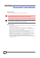
Document Conventions Icons Used in Figures Figures in this User’s Guide may use the following generic icons. The ZyXEL Device icon is not an exact representation of your device.
Safety Warnings Safety Warnings 1 For your safety, be sure to read and follow all warning notices and instructions. • Do NOT use this product near water, for example, in a wet basement or near a swimming pool. • Do NOT expose your device to dampness, dust or corrosive liquids. • Do NOT store things on the device. • Do NOT install, use, or service this device during a thunderstorm. There is a remote risk of electric shock from lightning. • Connect ONLY suitable accessories to the device.
Safety Warnings ZyXEL G-570S v2 User’s Guide 7
Safety Warnings 8 ZyXEL G-570S v2 User’s Guide
Contents Overview Contents Overview Introduction and Wizards ......................................................................................................21 Introducing the ZyXEL Device ................................................................................................... 23 ................................................................................................................................................... 30 Introducing the Web Configurator .............................
Contents Overview 10 ZyXEL G-570S v2 User’s Guide
Table of Contents Table of Contents About This User's Guide .......................................................................................................... 3 Document Conventions............................................................................................................ 4 Safety Warnings........................................................................................................................ 6 Contents Overview .......................................................
Table of Contents 2.2 Accessing the Web Configurator ......................................................................................... 31 Chapter 3 Wizards .................................................................................................................................... 35 3.1 Using the Wizards ............................................................................................................... 35 3.1.1 Wizard: Basic Settings ............................................
Table of Contents 7.5 Quality of Service ................................................................................................................ 59 7.5.1 WMM QoS .................................................................................................................. 59 7.6 Configuring Wireless ........................................................................................................... 60 7.6.1 Access Point Mode ..............................................................
Table of Contents Appendix A Product Specifications....................................................................................... 101 Appendix B Setting up Your Computer’s IP Address............................................................ 107 Appendix C Pop-up Windows, JavaScripts and Java Permissions ...................................... 123 Appendix D Wireless LANs ..................................................................................................
List of Figures List of Figures Figure 1 Internet Access Application ...................................................................................................... 24 Figure 2 Corporate Network Application ................................................................................................. 24 Figure 3 Wireless Client Application ...................................................................................................... 25 Figure 4 Bridge Application .........................
List of Figures Figure 39 Wireless Security: 802.1x ....................................................................................................... 77 Figure 40 MAC Filter .............................................................................................................................. 80 Figure 41 OTIST ..................................................................................................................................... 82 Figure 42 Example Wireless Client OTIST Screen .
List of Figures Figure 82 Red Hat 9.0: Checking TCP/IP Properties ......................................................................... 122 Figure 83 Pop-up Blocker ..................................................................................................................... 123 Figure 84 Internet Options: Privacy ...................................................................................................... 124 Figure 85 Internet Options: Privacy .......................................
List of Figures 18 ZyXEL G-570S v2 User’s Guide
List of Tables List of Tables Table 1 Front Panel LED Description .................................................................................................... 27 Table 2 Factory Defaults ........................................................................................................................ 29 Table 3 Global Icon Key ......................................................................................................................... 45 Table 4 Screens Summary ...................
List of Tables 20 ZyXEL G-570S v2 User’s Guide
P ART I Introduction and Wizards Introducing the ZyXEL Device (23) Introducing the Web Configurator (31) Wizards (35) 21
CHAPTER 1 Introducing the ZyXEL Device This chapter introduces the main applications and features of the ZyXEL Device. It also introduces the ways you can manage the ZyXEL Device. 1.1 Overview The ZyXEL Device is a 4-in-1 Access Point with Super G and Turbo G wireless technology. Access Point (AP), repeater, bridge and wireless client functions allow you to use the ZyXEL Device in various network deployments. Super G and Turbo G technology boost the wireless data throughput.
Chapter 1 Introducing the ZyXEL Device Figure 1 Internet Access Application 1.2.2 Corporate Network Access Application In situations where users need to access corporate network resources and the Internet, the ZyXEL Device is an ideal solution for wireless stations to connect to the corporate network without expensive network cabling. Stations A, B and C can access the wired network through the ZyXEL Devices.
Chapter 1 Introducing the ZyXEL Device Figure 3 Wireless Client Application 1.2.4 Bridge / Repeater The ZyXEL Device can act as a wireless network bridge and establish wireless links with other APs. The ZyXEL Devices in the following example are using bridge mode with a star configuration. A, B, C and D are connected to independent wired networks and have bridge connections at the same time (B, C and D can communicate with A).
Chapter 1 Introducing the ZyXEL Device Figure 5 Bridge Repeater Application 1.2.5 Access Point and Repeater Set the ZyXEL Device to AP+Repeater mode to have it simultaneously provide access for wireless clients and use the repeater function. This allows you to extend the coverage of your wireless network without installing Ethernet cable to connect the ZyXEL Device. In the following figure, B is in AP+Repeater mode. B functions as an AP for wireless clients C and D.
Chapter 1 Introducing the ZyXEL Device 1.4 Good Habits for Managing the ZyXEL Device Do the following things regularly to make the ZyXEL Device more secure and to manage the ZyXEL Device more effectively. • Change the password. Use a password that’s not easy to guess and that consists of different types of characters, such as numbers and letters. • Write down the password and put it in a safe place. • Back up the configuration (and make sure you know how to restore it).
Chapter 1 Introducing the ZyXEL Device Table 1 Front Panel LED Description LED COLOR STATUS DESCRIPTION WLAN Green Blinking The ZyXEL Device is sending or receiving data through the wireless LAN. On The ZyXEL Device is ready, but is not sending/receiving data. 1.6 Management Computer Setup You can connect a computer to the ZyXEL Device for management purposes either using an Ethernet connection (recommended for a first time management session) or wirelessly. 1.6.
Chapter 1 Introducing the ZyXEL Device " " The wireless stations and the ZyXEL Device must use the same SSID, channel and wireless security settings for wireless communication. If you do not enable any wireless security on your ZyXEL Device, your network traffic is visible to any wireless networking device that is within range. 1.7 Restarting the ZyXEL Device Press and immediately release the RESET button to restart the ZyXEL Device.
Chapter 1 30 ZyXEL G-570S v2 User’s Guide
CHAPTER 2 Introducing the Web Configurator This chapter describes how to configure the ZyXEL Device using the Wizard. 2.1 Web Configurator Overview The web configurator is an HTML-based management interface that allows easy ZyXEL Device setup and management via Internet browser. Use Internet Explorer 6.0 and later or Netscape Navigator 7.0 and later versions. The recommended screen resolution is 1024 by 768 pixels.
Chapter 2 Introducing the Web Configurator Figure 10 Web Configurator Address 5 Type "1234" (default) as the password and click Login. Figure 11 Login Screen Default password is 1234. 6 Select your language and click Apply. Figure 12 Language Screen 7 The following screen displays. Select Go Wizard Setup and click Apply to use the wizard setup screens for initial configuration (see Chapter 3 on page 35).
Chapter 2 Introducing the Web Configurator Figure 13 Select Wizard or Advanced Setup Screen ZyXEL G-570S v2 User’s Guide 33
Chapter 2 Introducing the Web Configurator 34 ZyXEL G-570S v2 User’s Guide
CHAPTER 3 Wizards This chapter shows you how to configure the ZyXEL Device’s basic features using the wizards. 3.1 Using the Wizards The wizards consist of a series of screens to help you configure your ZyXEL Device for wireless stations to access your wired LAN. Use the following buttons to navigate the Wizard: Back Click Back to return to the previous screen. Next Click Next to continue to the next screen. No configuration changes will be saved to the ZyXEL Device until you click Finish. 3.1.
Chapter 3 Wizards Figure 14 Wizard: Basic Settings Do not select this unless you have a router that can assign the ZyXEL Device an IP address. 3.1.2 Wizard: Wireless Settings Use this wizard screen to set up the wireless LAN. See the chapter on the wireless screens for background information. 1 The SSID is a unique name to identify the device in a wireless network. Enter up to 32 printable characters. Spaces are allowed.
Chapter 3 Wizards Figure 15 Wizard: Wireless Settings 3.1.3 Wizard: Security Settings Use this screen to configure security for your wireless LAN. The screen varies depending on what you select in the Encryption Method field. Select Disable to have no wireless security configured, select WEP, or select WPA-PSK if your wireless clients support WPA-PSK. Select WPA2-PSK if your wireless clients support WPA2-PSK Go to Wireless > Security if you want WPA2, WPA or 802.1x.
Chapter 3 Wizards Figure 16 Setup Wizard 3: Disable 3.1.3.2 WEP 1 WEP (Wired Equivalent Privacy) encrypts data frames before transmitting over the wireless network. Select 64-bit, 128-bit or 152-bit from the WEP Encryption dropdown list box and then follow the on-screen instructions to set up the WEP keys. 2 Choose an encryption level from the drop-down list. The higher the WEP encryption, the higher the security but the slower the throughput. 3 You can generate or manually enter a WEP key.
Chapter 3 Wizards Figure 17 Wizard 3: WEP Use Passphrase to automatically generate keys or manually enter a key in the Key 1 field. 3.1.3.3 WPA(2)-PSK Only select WPA-PSK or WPA2-PSK if your wireless clients support it. Type a pre-shared key from 8 to 63 ASCII characters (including spaces and symbols). This field is case-sensitive.
Chapter 3 Wizards Figure 18 Wizard 3: WPA(2)-PSK 3.1.4 Wizard: Confirm Your Settings This read-only screen shows the status of the current settings. Use the summary table to check whether what you have configured is correct. Click Finish to complete the wizard configuration and save your settings.
Chapter 3 Wizards Figure 19 Wizard: Confirm Your Settings For more detailed background information, see the rest of this User's Guide.
Chapter 3 Wizards 42 ZyXEL G-570S v2 User’s Guide
P ART II Advanced Navigating the Advanced Screens (45) Status Screens (47) System Screen (51) Wireless Screens (55) 43
CHAPTER 4 Navigating the Advanced Screens The Status screen is the first advanced screen that displays. This section explains how to navigate the advanced configuration screens. See Chapter 5 on page 47 for details about the individual screen. Figure 20 Status Screen The following table describes the global web configurator icons (in the upper right corner of most screens). Table 3 Global Icon Key ICON DESCRIPTION Click the Wizard icon to open the setup wizard.
Chapter 4 Navigating the Advanced Screens 4.0.1 Navigation Panel After you enter the password, use the links on the navigation panel to go to the various advanced screens. The following table describes the sub-menus. Table 4 Screens Summary LINK TAB FUNCTION Status This screen shows the ZyXEL Device’s general device, system and interface status information. Use this screen to access the wizard, and summary statistics tables.
CHAPTER 5 Status Screens This chapter describes the Status screens. 5.1 System Status Click Status to open the following screen. The Status screen display a snapshot of your device’s settings. You can also view network statistics and a list of wireless stations currently associated with your device. Note that these labels are READ-ONLY and are meant to be used for diagnostic purposes. Figure 21 Status The following table describes the labels in this screen.
Chapter 5 Status Screens Table 5 Status LABEL DESCRIPTION MAC Address This field displays the MAC address of the device. The MAC (Media Access Control) or Ethernet address on a LAN (Local Area Network) is unique to your computer. A network interface card such as an Ethernet adapter has a hardwired address that is assigned at the factory. This address follows an industry standard that ensures no other adapter has a similar address.
Chapter 5 Status Screens Figure 22 Status: View Statistics The following table describes the labels in this screen. Table 6 Status: View Statistics LABEL DESCRIPTION Ethernet Packets This row displays the numbers of packets received and transmitted by the Ethernet port. Bytes This row displays the numbers of bytes received and transmitted by the Ethernet port. Wireless Unicast Packets This row displays the numbers of unicast packets received and transmitted by the wireless adapter.
Chapter 5 Status Screens Figure 23 Status: View Association List The following table describes the labels in this screen. Table 7 Status: View Association List LABEL DESCRIPTION # This is the index number of an associated wireless station. MAC Address This field displays the MAC address of an associated wireless station. IP Address This field displays the IP address of an associated wireless station. Signal Strength This field displays the signal strength of each associated wireless station.
CHAPTER 6 System Screen This chapter provides information on the System screen. 6.1 TCP/IP Parameters 6.1.1 IP Address Assignment Every computer on the Internet must have a unique IP address. If your networks are isolated from the Internet, for instance, only between your two branch offices, you can assign any IP addresses to the hosts without problems. However, the Internet Assigned Numbers Authority (IANA) has reserved the following three blocks of IP addresses specifically for private networks.
Chapter 6 System Screen Where you obtain your network number depends on your particular situation. If the ISP or your network administrator assigns you a block of registered IP addresses, follow their instructions in selecting the IP addresses and the subnet mask. If the ISP did not explicitly give you an IP network number, then most likely you have a single user account and the ISP will assign you a dynamic IP address when the connection is established.
Chapter 6 System Screen Table 10 System Settings LABEL DESCRIPTION Use fixed IP address Select this option to have your device use a static IP address. When you select this option, fill in the fields below. IP Address Enter the IP address of your device in dotted decimal notation. Subnet Mask Enter the subnet mask. Gateway IP Address Type the IP address of the gateway. The gateway is a router or switch on the same network segment as the device.
Chapter 6 System Screen 54 ZyXEL G-570S v2 User’s Guide
CHAPTER 7 Wireless Screens This chapter discusses how to configure the wireless network settings in your ZyXEL Device. See the appendices for more detailed information about wireless networks. 7.1 Wireless Network Overview The following figure provides an example of a wireless network. Figure 26 Example of a Wireless Network The wireless network is the part in the blue circle.
Chapter 7 Wireless Screens Like radio stations or television channels, each wireless network uses a specific channel, or frequency, to send and receive information. • Every device in the same wireless network must use security compatible with the AP. Security stops unauthorized devices from using the wireless network. It can also protect the information that is sent in the wireless network. 7.
Chapter 7 Wireless Screens Unauthorized wireless devices can still see the information that is sent in the wireless network, even if they cannot use the wireless network. Furthermore, there are ways for unauthorized wireless users to get a valid user name and password. Then, they can use that user name and password to use the wireless network. 7.2.4 Encryption Wireless networks can use encryption to protect the information that is sent in the wireless network. Encryption is like a secret code.
Chapter 7 Wireless Screens 7.2.5 One-Touch Intelligent Security Technology (OTIST) With ZyXEL’s OTIST, you set up the SSID and the encryption (WEP or WPA-PSK) on the ZyXEL Device. Then, the ZyXEL Device transfers them to the devices in the wireless networks. As a result, you do not have to set up the SSID and encryption on every device in the wireless network. The devices in the wireless network have to support OTIST, and they have to be in range of the ZyXEL Device when you activate it. See Section 7.
Chapter 7 Wireless Screens Table 12 Additional Wireless Terms TERM DESCRIPTION Fragmentation Threshold A small fragmentation threshold is recommended for busy networks, while a larger threshold provides faster performance if the network is not very busy. Roaming If you have two or more ZyXEL Devices (or other wireless access points) on your wireless network, you can enable this option so that wireless devices can change locations without having to log in again.
Chapter 7 Wireless Screens 7.6 Configuring Wireless Click Wireless to display the Wireless Settings screen.The screen varies depending upon the operation mode you select. 7.6.1 Access Point Mode Select Access Point in the Operation Mode field to display the screen as shown next. This mode has the device act as an access point (AP) through which wireless stations can communicate and/or access a wired network.
Chapter 7 Wireless Screens Table 14 Wireless Settings: Access Point (continued) LABEL SSID DESCRIPTION Wireless stations associating to the access point (AP) must have the same SSID. Enter a descriptive name (up to 32 printable characters) for the wireless LAN. Spaces are allowed. Note: If you are configuring the device from a computer connected to the wireless LAN and you change the device's SSID, channel or security settings, you will lose your wireless connection when you press Apply to confirm.
Chapter 7 Wireless Screens Table 14 Wireless Settings: Access Point (continued) LABEL DESCRIPTION Output Power Management Set the output power of the device in this field. If there is a high density of APs within an area, decrease the output power of the device to reduce interference with other APs. The options are Full, 50%, 25%, 12% and Min. Data Rate Management Use this field to select a maximum data rate for the wireless connection(s).
Chapter 7 Wireless Screens Figure 28 Wireless Settings: Wireless Client The following table describes the labels in this screen. Table 15 Wireless Settings: Wireless Client LABEL DESCRIPTION Basic Settings Operation Mode Select the operating mode from the drop-down list. The options are Access Point, Wireless Client, Bridge and AP+Repeater. SSID Wireless stations associating to the access point (AP) must have the same SSID.
Chapter 7 Wireless Screens Table 15 Wireless Settings: Wireless Client (continued) LABEL DESCRIPTION Output Power Management Set the output power of the device in this field. If there is a high density of APs within an area, decrease the output power of the device to reduce interference with other APs. The options are Full, 50%, 25%, 12% and Min. Data Rate Management Use this field to select a maximum data rate for the wireless connection(s).
Chapter 7 Wireless Screens The following table describes the labels in this screen. Table 16 Wireless: the AP Survey Screen LABEL DESCRIPTION Site Survey SSID This field displays the SSID (Service Set IDentifier) of each access point. BSSID This field displays the MAC address of each access point. Channel This field displays the channel number used by each access point. Wireless Mode This field displays the wireless networking standard the access point is using.
Chapter 7 Wireless Screens Figure 30 Bridging Example Be careful to avoid bridge loops when you enable bridging in the ZyXEL Device. Bridge loops cause broadcast traffic to circle the network endlessly, resulting in possible throughput degradation and disruption of communications. The following examples show two network topologies that can lead to this problem: If two or more ZyXEL Devices (in bridge mode) are connected to the same hub as shown next.
Chapter 7 Wireless Screens Figure 32 Bridge Loop: Bridge Connected to Wired LAN To prevent bridge loops, ensure that your ZyXEL Device is not set to bridge mode while connected to both wired and wireless segments of the same LAN. Select Bridge as the Operation Mode to have the device act as a wireless bridge only.
Chapter 7 Wireless Screens The following table describes the labels in this screen. Table 17 Wireless Settings: Bridge LABEL DESCRIPTION Basic Settings Operation Mode Select the operating mode from the drop-down list. The options are Access Point, Wireless Client, Bridge and AP+Repeater. Note: If you are configuring the device from a computer connected to the wireless LAN and you change the device to use bridge mode, you will lose your wireless connection when you click Apply to save your settings.
Chapter 7 Wireless Screens Table 17 Wireless Settings: Bridge (continued) LABEL Preamble Type DESCRIPTION Preamble is used to signal that data is coming to the receiver. Short preamble increases performance as less time sending preamble means more time for sending data. All IEEE 802.11b compliant wireless adapters support long preamble, but not all support short preamble.
Chapter 7 Wireless Screens Figure 34 Wireless Settings: AP+Repeater The following table describes the labels in this screen. Table 18 Wireless Settings: AP + Repeater LABEL DESCRIPTION Basic Settings Operation Mode 70 Select the operating mode from the drop-down list. The options are Access Point, Wireless Client, Bridge and AP+Repeater.
Chapter 7 Wireless Screens Table 18 Wireless Settings: AP + Repeater (continued) LABEL SSID DESCRIPTION Wireless stations associating to the access point (AP) must have the same SSID. Enter a descriptive name (up to 32 printable characters) for the wireless LAN. Spaces are allowed.
Chapter 7 Wireless Screens Table 18 Wireless Settings: AP + Repeater (continued) LABEL DESCRIPTION Number of Wireless Stations Allowed to Associate: Use this field to set a maximum number of wireless stations that may connect to the device. Enter the number (from 1 to 32) of wireless stations allowed. Radio Enable Turn on the wireless adapter to allow wireless communications between the device and other IEEE 802.11b and IEEE 802.11g compliant wireless devices.
Chapter 7 Wireless Screens " The encryption methods available depend on the Operation Mode you select in the Wireless > Wireless screen. 7.7.1 Wireless Security: Disable If you do not enable any wireless security on your device, your network is accessible to any wireless networking device that is within range. Figure 35 Wireless Security: Disable The following table describes the labels in this screen.
Chapter 7 Wireless Screens Figure 36 Wireless Security: WEP The following table describes the labels in this screen. Table 20 Wireless Security: WEP LABEL DESCRIPTION Encryption Method Select WEP if you want to configure WEP encryption parameters. Authentication Type Select Auto, Open or Shared from the drop-down list box. WEP Encryption Select 64 bit WEP, 128 bit WEP or 152 bit WEP to enable data encryption.
Chapter 7 Wireless Screens 7.7.3 Wireless Security: WPA(2)-PSK Select WPA-PSK, WPA2-PSK or WPA-PSK & WPA2-PSK in the Encryption Method drop down list-box to display the screen displays as next. Figure 37 Wireless Security: WPA(2)-PSK The following table describes the labels in this screen. Table 21 Wireless Security: WPA-PSK LABEL DESCRIPTION Encryption Method Select WPA-PSK, WPA2-PSK or WPA-PSK & WPA2-PSK if you want to configure a pre-shared key.
Chapter 7 Wireless Screens Figure 38 Wireless Security: WPA(2) The following table describes the labels in this screen. Table 22 Wireless Security: WPA(2) LABEL DESCRIPTION Encryption Method Select WPA, WPA2 or WPA & WPA2 to configure user authentication and improved data encryption. Note: WPA, WPA2 and IEEE 802.1x wireless security are not available when you use Wireless Client, Bridge or AP+Repeater mode. Note: You can only use WEP keys to encrypt traffic between APs.
Chapter 7 Wireless Screens Table 22 Wireless Security: WPA(2) (continued) LABEL DESCRIPTION Apply Click Apply to save your changes back to the device. Reset Click Reset to begin configuring this screen afresh. 7.7.5 Wireless Security: IEEE 802.1x The IEEE 802.1x standard outlines enhanced security methods for both the authentication of wireless stations and encryption key management.
Chapter 7 Wireless Screens The following table describes the labels in this screen. Table 23 Wireless Security: 802.1x LABEL DESCRIPTION Encryption Method Select 802.1X to configure authentication of wireless stations and encryption key management. Note: WPA, WPA2 and IEEE 802.1x wireless security are not available when you use Bridge or AP+Repeater mode. You can only use WEP keys to encrypt traffic between APs.
Chapter 7 Wireless Screens The following applies if you set the device to client mode and want to connect to an AP that uses a MAC filter. After the device turns on in client mode, it clones the MAC address of the first packets that it receives from devices connected to the Ethernet port. It uses this MAC address on the packets that it sends to an AP. All of the packets that the device sends to an AP will appear to be from the first device that connected to the Ethernet port.
Chapter 7 Wireless Screens Figure 40 MAC Filter The following table describes the labels in this screen. Table 24 MAC Filter 80 LABEL DESCRIPTION Active Select the check box to enable MAC address filtering and define the filter action for the list of MAC addresses in the MAC address filter table. Select Allow the following MAC address to associate to permit access to the device. MAC addresses not listed will be denied access to the device.
Chapter 7 Wireless Screens 7.9 OTIST In a wireless network, the wireless clients must have the same SSID and security settings as the access point (AP) or wireless router (we will refer to both as “AP” here) in order to associate with it. Traditionally this meant that you had to configure the settings on the AP and then manually configure the exact same settings on each wireless client.
Chapter 7 Wireless Screens Figure 41 OTIST The following table describes the labels in this screen. Table 25 OTIST LABEL DESCRIPTION One-Touch Intelligent Security Technology Setup Key Enter the setup key of up to eight printable characters. The default OTIST setup key is "01234567". Note: If you change the OTIST setup key here, you must also make the same change on the wireless client(s). Yes! To have OTIST automatically generate a WPA-PSK key, select this check box.
Chapter 7 Wireless Screens 7.9.1.3.1 Wireless Client Mode: OTIST Button If you use the OTIST button, the default (01234567) or previous saved (through the web configurator) Setup key is used. Double-click the OTIST button to automatically change the ZyXEL Device to wireless client mode and start OTIST. 7.9.1.3.2 Wireless Client Mode: Web Configurator Start the web configurator and click Wireless. Select Wireless Client in the Operation Mode field. Click on the OTIST tab. The screen displays as shown.
Chapter 7 Wireless Screens Figure 45 OTIST in Progress (AP) Figure 46 OTIST in Progress (Client) • In the wireless client, you see this screen if it can't find an OTIST-enabled AP (with the same Setup key). Click OK to go back to the ZyXEL utility main screen. Figure 47 No AP with OTIST Found • If there is more than one OTIST-enabled AP within range, you see a screen asking you to select one AP to get settings from. 7.9.
Chapter 7 Wireless Screens 3 When the wireless client finds an OTIST-enabled AP, you must still click Start in the AP OTIST web configurator screen or hold in the OTIST button (for one or two seconds) for the AP to transfer settings. 4 If you change the SSID or the keys on the AP after using OTIST, you need to run OTIST again or enter them manually in the wireless client(s). 5 If you configure OTIST to generate a WPA-PSK key, this key changes each time you run OTIST.
Chapter 7 Wireless Screens 86 ZyXEL G-570S v2 User’s Guide
P ART III Management and Troubleshooting Management Screens (89) Troubleshooting (95) 87
CHAPTER 8 Management Screens This chapter describes the Maintenance screens. 8.1 Maintenance Overview Use these maintenance screens to change the password, view logs, back up or restore the ZyXEL Device’s configuration and change the web configurator language. 8.2 Password To change your device's password (recommended), click Management. The screen appears as shown. This screen allows you to change the device's password.
Chapter 8 Management Screens Table 26 Management: Password (continued) LABEL DESCRIPTION Apply Click Apply to save your changes back to the device. Cancel Click Cancel to reload the previous configuration for this screen. 8.3 Logs Click Management > Logs to open the Logs screen. You can view logs and alert messages in this screen. Once the log table is full, old logs are deleted as new logs are created. Click a column heading to sort the entries. A triangle indicates the direction of the sort order.
Chapter 8 Management Screens 8.4 Configuration File The configuration file (often called the romfile or rom-0) contains the factory default settings such as password and TCP/IP Setup, etc. It arrives from ZyXEL with a .rom filename extension. Once you have customized the device's settings, they can be saved back to your computer under a filename of your choosing. Click Management > Configuration File.
Chapter 8 Management Screens 8.4.2 Restore Configuration Restore configuration allows you to upload a new or previously saved configuration file from your computer to your device. Table 28 Management: Configuration File: Restore Configuration " LABEL DESCRIPTION File Path Type in the location of the file you want to upload in this field or click Browse ... to find it. Browse... Click Browse... to find the file you want to upload. Remember that you must decompress compressed (.
Chapter 8 Management Screens Figure 54 Configuration Upload Error 8.4.3 Back to Factory Defaults Clicking the RESET button in this section clears all user-entered configuration information and returns the device to its factory defaults. The following warning screen will appear. Figure 55 Reset Warning Message You can also press the RESET button on the rear panel to reset the factory defaults of your device. Refer to the section on resetting the device for more information on the RESET button. 8.
Chapter 8 Management Screens The following table describes the labels in this screen. Table 29 Management: F/W Upload " LABEL DESCRIPTION File Path Type in the location of the file you want to upload in this field or click Browse ... to find it. Browse... Click Browse... to find the .rmt file you want to upload. Remember that you must decompress compressed (.zip) files before you can upload them. Upload Click Upload to begin the upload process. This process may take up to two minutes.
CHAPTER 9 Troubleshooting This chapter offers some suggestions to solve problems you might encounter. The potential problems are divided into the following categories. • Power, Hardware Connections, and LEDs • ZyXEL Device Access and Login • Internet Access 9.1 Power, Hardware Connections, and LEDs V The ZyXEL Device does not turn on. None of the LEDs turn on. 6 Make sure you are using the power adaptor or cord included with the ZyXEL Device.
Chapter 9 Troubleshooting 9.2 ZyXEL Device Access and Login V I forgot the IP address for the ZyXEL Device. 1 The default IP address is 192.168.1.2. 2 If this does not work, you have to reset the device to its factory defaults. See Section 1.8 on page 29. V I forgot the password. 1 The default password is 1234. 2 If this does not work, you have to reset the device to its factory defaults. See Section 1.8 on page 29. V I cannot see or access the Login screen in the web configurator.
Chapter 9 Troubleshooting 1 Make sure you have entered the user name and password correctly. The default password is 1234. This field is case-sensitive, so make sure [Caps Lock] is not on. 2 You cannot log in to the web configurator while someone is using Telnet to access the ZyXEL Device. Log out of the ZyXEL Device in the other session, or ask the person who is logged in to log out. 3 Disconnect and re-connect the power adaptor or cord to the ZyXEL Device.
Chapter 9 Troubleshooting 9.3 Internet Access V I cannot access the Internet. 1 Check the hardware connections, and make sure the LEDs are behaving as expected. See the Quick Start Guide and Section 1.5 on page 27. 2 If you are trying to access the Internet wirelessly, make sure the wireless settings in the wireless client are the same as the settings in the AP. 3 Disconnect all the cables from your device, and follow the directions in the Quick Start Guide again.
P ART IV Appendices and Index Product Specifications (101) Setting up Your Computer’s IP Address (107) Pop-up Windows, JavaScripts and Java Permissions (123) Wireless LANs (129) Customer Support (143) Legal Information (147) Index (151) 99
APPENDIX A Product Specifications The following tables summarize the ZyXEL Device’s hardware and firmware features. Hardware Specifications Table 30 Hardware Specifications Default IP Address 192.168.1.2 Default Subnet Mask 255.255.255.0 (24 bits) Default Password 1234 Dimensions 112 mm (Wide) × 106 mm (Deep) × 28.
Appendix A Product Specifications Table 31 Feature Specifications (continued) Roaming IEEE 802.11g compliant IEEE 802.11b compliant IEEE 802.11f partially compliant (without re-authentication) Operating Modes Access Point Client Bridge Access Point and Repeater Wireless Links The ZyXEL Device can act as a bridge, establishing wireless links with other APs or as a repeater, establishing wireless links to APs. Up to four bridge links. Two or more repeater links are supported.
Appendix A Product Specifications Table 31 Feature Specifications (continued) 10/100M Autonegotiating Ethernet/ Fast Ethernet Interface This auto-negotiating feature allows the ZyXEL Device to detect the speed of incoming transmissions and adjust appropriately without manual intervention. It allows data transfer of either 10 Mbps or 100 Mbps in either half-duplex or full-duplex mode depending on your Ethernet network. Ethernet port connections can be in half-duplex or full-duplex mode.
Appendix A Product Specifications Table 31 Feature Specifications (continued) Output Power Management Output Power Management is the ability to set the level of output power. There may be interference or difficulty with channel assignment when there is a high density of APs within a coverage area. In this case you can lower the output power of each access point, thus enabling you to place access points closer together.
Appendix A Product Specifications Table 33 Approvals (continued) EMI EMS North America FCC Part 15 Class B European Union (CE mark) EN55022 Class B EN61000-3-2 EN61000-3-3 European Union (CE mark) ELECTROSTATIC DISCHARGE EN61000-4-2 RADIO-FREQUENCY ELECTROMAGNETIC FIELD EN61000-4-3 EFT/BURST EN61000-4-4 SURGE EN61000-4-5 CONDUCTED SUSCEPTIBILITY EN61000-4-6 POWER MAGNETIC EN61000-4-8 VOLTAGE DIPS/ INTERRUPTION EN61000-4-11 EM FIELD FROM DIGITAL TELEPHONES ENV50204 LAN COMPATIBILITY
Appendix A Product Specifications Table 34 Power Adaptor Specifications (continued) NORTH AMERICAN PLUG STANDARDS AC Power Adapter Model AD-121A Input Power 120 Volts AC 60Hz Output Power 12 Volts DC ±5%, 1 Amp Power Consumption 12 Watts Safety Standards UL UK PLUG STANDARDS 106 AC Power Adapter Model AD-121AD Input Power 240 Volts AC 50Hz Output Power 12 Volts DC ±5% 1 Amp Power Consumption 12 Watts Safety Standards CE mark, EN60950 (2001) ZyXEL G-570S v2 User’s Guide
APPENDIX B Setting up Your Computer’s IP Address All computers must have a 10M or 100M Ethernet adapter card and TCP/IP installed. Windows 95/98/Me/NT/2000/XP, Macintosh OS 7 and later operating systems and all versions of UNIX/LINUX include the software components you need to install and use TCP/IP on your computer. Windows 3.1 requires the purchase of a third-party TCP/IP application package.
Appendix B Setting up Your Computer’s IP Address Figure 60 WIndows 95/98/Me: Network: Configuration Installing Components The Network window Configuration tab displays a list of installed components. You need a network adapter, the TCP/IP protocol and Client for Microsoft Networks. If you need the adapter: 1 In the Network window, click Add. 2 Select Adapter and then click Add. 3 Select the manufacturer and model of your network adapter and then click OK.
Appendix B Setting up Your Computer’s IP Address Configuring 1 In the Network window Configuration tab, select your network adapter's TCP/IP entry and click Properties 2 Click the IP Address tab. • If your IP address is dynamic, select Obtain an IP address automatically. • If you have a static IP address, select Specify an IP address and type your information into the IP Address and Subnet Mask fields. Figure 61 Windows 95/98/Me: TCP/IP Properties: IP Address 3 Click the DNS Configuration tab.
Appendix B Setting up Your Computer’s IP Address Figure 62 Windows 95/98/Me: TCP/IP Properties: DNS Configuration 4 Click the Gateway tab. • If you do not know your gateway’s IP address, remove previously installed gateways. • If you have a gateway IP address, type it in the New gateway field and click Add. 5 Click OK to save and close the TCP/IP Properties window. 6 Click OK to close the Network window. Insert the Windows CD if prompted.
Appendix B Setting up Your Computer’s IP Address Figure 63 Windows XP: Start Menu 2 In the Control Panel, double-click Network Connections (Network and Dial-up Connections in Windows 2000/NT). Figure 64 Windows XP: Control Panel 3 Right-click Local Area Connection and then click Properties.
Appendix B Setting up Your Computer’s IP Address Figure 65 Windows XP: Control Panel: Network Connections: Properties 4 Select Internet Protocol (TCP/IP) (under the General tab in Win XP) and then click Properties. Figure 66 Windows XP: Local Area Connection Properties 5 The Internet Protocol TCP/IP Properties window opens (the General tab in Windows XP). • If you have a dynamic IP address click Obtain an IP address automatically.
Appendix B Setting up Your Computer’s IP Address Figure 67 Windows XP: Internet Protocol (TCP/IP) Properties 6 If you do not know your gateway's IP address, remove any previously installed gateways in the IP Settings tab and click OK. Do one or more of the following if you want to configure additional IP addresses: • In the IP Settings tab, in IP addresses, click Add. • In TCP/IP Address, type an IP address in IP address and a subnet mask in Subnet mask, and then click Add.
Appendix B Setting up Your Computer’s IP Address Figure 68 Windows XP: Advanced TCP/IP Properties 7 In the Internet Protocol TCP/IP Properties window (the General tab in Windows XP): • Click Obtain DNS server address automatically if you do not know your DNS server IP address(es). • If you know your DNS server IP address(es), click Use the following DNS server addresses, and type them in the Preferred DNS server and Alternate DNS server fields.
Appendix B Setting up Your Computer’s IP Address Figure 69 Windows XP: Internet Protocol (TCP/IP) Properties 8 Click OK to close the Internet Protocol (TCP/IP) Properties window. 9 Click Close (OK in Windows 2000/NT) to close the Local Area Connection Properties window. 10 Close the Network Connections window (Network and Dial-up Connections in Windows 2000/NT). 11 Turn on your ZyXEL Device and restart your computer (if prompted).
Appendix B Setting up Your Computer’s IP Address Figure 70 Macintosh OS 8/9: Apple Menu 2 Select Ethernet built-in from the Connect via list. Figure 71 Macintosh OS 8/9: TCP/IP 3 For dynamically assigned settings, select Using DHCP Server from the Configure: list. 4 For statically assigned settings, do the following: • From the Configure box, select Manually.
Appendix B Setting up Your Computer’s IP Address • Type your IP address in the IP Address box. • Type your subnet mask in the Subnet mask box. • Type the IP address of your ZyXEL Device in the Router address box. 5 Close the TCP/IP Control Panel. 6 Click Save if prompted, to save changes to your configuration. 7 Turn on your ZyXEL Device and restart your computer (if prompted). Verifying Settings Check your TCP/IP properties in the TCP/IP Control Panel window.
Appendix B Setting up Your Computer’s IP Address Figure 73 Macintosh OS X: Network 4 For statically assigned settings, do the following: • From the Configure box, select Manually. • Type your IP address in the IP Address box. • Type your subnet mask in the Subnet mask box. • Type the IP address of your ZyXEL Device in the Router address box. 5 Click Apply Now and close the window. 6 Turn on your ZyXEL Device and restart your computer (if prompted).
Appendix B Setting up Your Computer’s IP Address " Make sure you are logged in as the root administrator. Using the K Desktop Environment (KDE) Follow the steps below to configure your computer IP address using the KDE. 1 Click the Red Hat button (located on the bottom left corner), select System Setting and click Network. Figure 74 Red Hat 9.0: KDE: Network Configuration: Devices 2 Double-click on the profile of the network card you wish to configure.
Appendix B Setting up Your Computer’s IP Address • If you have a dynamic IP address, click Automatically obtain IP address settings with and select dhcp from the drop down list. • If you have a static IP address, click Statically set IP Addresses and fill in the Address, Subnet mask, and Default Gateway Address fields. 3 Click OK to save the changes and close the Ethernet Device General screen. 4 If you know your DNS server IP address(es), click the DNS tab in the Network Configuration screen.
Appendix B Setting up Your Computer’s IP Address Figure 78 Red Hat 9.0: Dynamic IP Address Setting in ifconfig-eth0 DEVICE=eth0 ONBOOT=yes BOOTPROTO=dhcp USERCTL=no PEERDNS=yes TYPE=Ethernet • If you have a static IP address, enter static in the BOOTPROTO= field. Type IPADDR= followed by the IP address (in dotted decimal notation) and type NETMASK= followed by the subnet mask. The following example shows an example where the static IP address is 192.168.1.10 and the subnet mask is 255.255.255.0.
Appendix B Setting up Your Computer’s IP Address Verifying Settings Enter ifconfig in a terminal screen to check your TCP/IP properties. Figure 82 Red Hat 9.0: Checking TCP/IP Properties [root@localhost]# ifconfig eth0 Link encap:Ethernet HWaddr 00:50:BA:72:5B:44 inet addr:172.23.19.129 Bcast:172.23.19.255 Mask:255.255.255.
APPENDIX C Pop-up Windows, JavaScripts and Java Permissions In order to use the web configurator you need to allow: • Web browser pop-up windows from your device. • JavaScripts (enabled by default). • Java permissions (enabled by default). " Internet Explorer 6 screens are used here. Screens for other Internet Explorer versions may vary. Internet Explorer Pop-up Blockers You may have to disable pop-up blocking to log into your device.
Appendix C Pop-up Windows, JavaScripts and Java Permissions 2 Clear the Block pop-ups check box in the Pop-up Blocker section of the screen. This disables any web pop-up blockers you may have enabled. Figure 84 Internet Options: Privacy 3 Click Apply to save this setting. Enable pop-up Blockers with Exceptions Alternatively, if you only want to allow pop-up windows from your device, see the following steps. 1 In Internet Explorer, select Tools, Internet Options and then the Privacy tab.
Appendix C Pop-up Windows, JavaScripts and Java Permissions Figure 85 Internet Options: Privacy 3 Type the IP address of your device (the web page that you do not want to have blocked) with the prefix “http://”. For example, http://192.168.167.1. 4 Click Add to move the IP address to the list of Allowed sites.
Appendix C Pop-up Windows, JavaScripts and Java Permissions 5 Click Close to return to the Privacy screen. 6 Click Apply to save this setting. JavaScripts If pages of the web configurator do not display properly in Internet Explorer, check that JavaScripts are allowed. 1 In Internet Explorer, click Tools, Internet Options and then the Security tab. Figure 87 Internet Options: Security 2 3 4 5 6 126 Click the Custom Level... button. Scroll down to Scripting.
Appendix C Pop-up Windows, JavaScripts and Java Permissions Figure 88 Security Settings - Java Scripting Java Permissions 1 2 3 4 5 From Internet Explorer, click Tools, Internet Options and then the Security tab. Click the Custom Level... button. Scroll down to Microsoft VM. Under Java permissions make sure that a safety level is selected. Click OK to close the window.
Appendix C Pop-up Windows, JavaScripts and Java Permissions JAVA (Sun) 1 From Internet Explorer, click Tools, Internet Options and then the Advanced tab. 2 Make sure that Use Java 2 for
APPENDIX D Wireless LANs Wireless LAN Topologies This section discusses ad-hoc and infrastructure wireless LAN topologies. Ad-hoc Wireless LAN Configuration The simplest WLAN configuration is an independent (Ad-hoc) WLAN that connects a set of computers with wireless adapters (A, B, C). Any time two or more wireless adapters are within range of each other, they can set up an independent network, which is commonly referred to as an ad-hoc network or Independent Basic Service Set (IBSS).
Appendix D Wireless LANs Figure 92 Basic Service Set ESS An Extended Service Set (ESS) consists of a series of overlapping BSSs, each containing an access point, with each access point connected together by a wired network. This wired connection between APs is called a Distribution System (DS). This type of wireless LAN topology is called an Infrastructure WLAN. The Access Points not only provide communication with the wired network but also mediate wireless network traffic in the immediate neighborhood.
Appendix D Wireless LANs Figure 93 Infrastructure WLAN Channel A channel is the radio frequency(ies) used by IEEE 802.11a/b/g wireless devices. Channels available depend on your geographical area. You may have a choice of channels (for your region) so you should use a different channel than an adjacent AP (access point) to reduce interference. Interference occurs when radio signals from different access points overlap causing interference and degrading performance.
Appendix D Wireless LANs Figure 94 RTS/CTS When station A sends data to the AP, it might not know that the station B is already using the channel. If these two stations send data at the same time, collisions may occur when both sets of data arrive at the AP at the same time, resulting in a loss of messages for both stations. RTS/CTS is designed to prevent collisions due to hidden nodes.
Appendix D Wireless LANs If the Fragmentation Threshold value is smaller than the RTS/CTS value (see previously) you set then the RTS (Request To Send)/CTS (Clear to Send) handshake will never occur as data frames will be fragmented before they reach RTS/CTS size. Preamble Type Preamble is used to signal that data is coming to the receiver. Short and Long refer to the length of the synchronization field in a packet.
Appendix D Wireless LANs Wireless security methods available on the ZyXEL Device are data encryption, wireless client authentication, restricting access by device MAC address and hiding the ZyXEL Device identity. The following figure shows the relative effectiveness of these wireless security methods available on your ZyXEL Device.
Appendix D Wireless LANs Determines the network services available to authenticated users once they are connected to the network. • Accounting Keeps track of the client’s network activity. RADIUS is a simple package exchange in which your AP acts as a message relay between the wireless client and the network RADIUS server.
Appendix D Wireless LANs For EAP-TLS authentication type, you must first have a wired connection to the network and obtain the certificate(s) from a certificate authority (CA). A certificate (also called digital IDs) can be used to authenticate users and a CA issues certificates and guarantees the identity of each certificate owner. EAP-MD5 (Message-Digest Algorithm 5) MD5 authentication is the simplest one-way authentication method. The authentication server sends a challenge to the wireless client.
Appendix D Wireless LANs Dynamic WEP Key Exchange The AP maps a unique key that is generated with the RADIUS server. This key expires when the wireless connection times out, disconnects or reauthentication times out. A new WEP key is generated each time reauthentication is performed. If this feature is enabled, it is not necessary to configure a default encryption key in the Wireless screen. You may still configure and store keys here, but they will not be used while Dynamic WEP is enabled.
Appendix D Wireless LANs Encryption Both WPA and WPA2 improve data encryption by using Temporal Key Integrity Protocol (TKIP), Message Integrity Check (MIC) and IEEE 802.1x. WPA and WPA2 use Advanced Encryption Standard (AES) in the Counter mode with Cipher block chaining Message authentication code Protocol (CCMP) to offer stronger encryption than TKIP. TKIP uses 128-bit keys that are dynamically generated and distributed by the authentication server.
Appendix D Wireless LANs Wireless Client WPA Supplicants A wireless client supplicant is the software that runs on an operating system instructing the wireless client how to use WPA. At the time of writing, the most widely available supplicant is the WPA patch for Windows XP, Funk Software's Odyssey client. The Windows XP patch is a free download that adds WPA capability to Windows XP's built-in "Zero Configuration" wireless client. However, you must run Windows XP to use it.
Appendix D Wireless LANs 4 The AP and wireless clients use the TKIP or AES encryption process to encrypt data exchanged between them. Figure 96 WPA(2)-PSK Authentication Security Parameters Summary Refer to this table to see what other security parameters you should configure for each Authentication Method/ key management protocol type. MAC address filters are not dependent on how you configure these security features.
Appendix D Wireless LANs Positioning the antennas properly increases the range and coverage area of a wireless LAN. Antenna Characteristics Frequency An antenna in the frequency of 2.4GHz (IEEE 802.11b) or 5GHz(IEEE 802.11a) is needed to communicate efficiently in a wireless LAN. Radiation Pattern A radiation pattern is a diagram that allows you to visualize the shape of the antenna’s coverage area.
Appendix D Wireless LANs For omni-directional antennas mounted on a table, desk, and so on, point the antenna up. For omni-directional antennas mounted on a wall or ceiling, point the antenna down. For a single AP application, place omni-directional antennas as close to the center of the coverage area as possible. For directional antennas, point the antenna in the direction of the desired coverage area.
APPENDIX E Customer Support Please have the following information ready when you contact customer support. Required Information • • • • Product model and serial number. Warranty Information. Date that you received your device. Brief description of the problem and the steps you took to solve it. Corporate Headquarters (Worldwide) • • • • • • • Support E-mail: support@zyxel.com.tw Sales E-mail: sales@zyxel.com.tw Telephone: +886-3-578-3942 Fax: +886-3-578-2439 Web Site: www.zyxel.com, www.europe.zyxel.
Appendix E Customer Support Denmark • • • • • • Support E-mail: support@zyxel.dk Sales E-mail: sales@zyxel.dk Telephone: +45-39-55-07-00 Fax: +45-39-55-07-07 Web Site: www.zyxel.dk Regular Mail: ZyXEL Communications A/S, Columbusvej, 2860 Soeborg, Denmark Finland • • • • • • Support E-mail: support@zyxel.fi Sales E-mail: sales@zyxel.fi Telephone: +358-9-4780-8411 Fax: +358-9-4780 8448 Web Site: www.zyxel.
Appendix E Customer Support • • • • Telephone: +7-3272-590-698 Fax: +7-3272-590-689 Web Site: www.zyxel.kz Regular Mail: ZyXEL Kazakhstan, 43, Dostyk ave.,Office 414, Dostyk Business Centre, 050010, Almaty, Republic of Kazakhstan North America • • • • • • • Support E-mail: support@zyxel.com Sales E-mail: sales@zyxel.com Telephone: +1-800-255-4101, +1-714-632-0882 Fax: +1-714-632-0858 Web Site: www.us.zyxel.com FTP Site: ftp.us.zyxel.com Regular Mail: ZyXEL Communications Inc., 1130 N. Miller St.
Appendix E Customer Support • Web Site: www.zyxel.es • Regular Mail: ZyXEL Communications, Arte, 21 5ª planta, 28033 Madrid, Spain Sweden • • • • • • Support E-mail: support@zyxel.se Sales E-mail: sales@zyxel.se Telephone: +46-31-744-7700 Fax: +46-31-744-7701 Web Site: www.zyxel.se Regular Mail: ZyXEL Communications A/S, Sjöporten 4, 41764 Göteborg, Sweden Ukraine • • • • • • Support E-mail: support@ua.zyxel.com Sales E-mail: sales@ua.zyxel.
APPENDIX F Legal Information Copyright Copyright © 2006 by ZyXEL Communications Corporation. The contents of this publication may not be reproduced in any part or as a whole, transcribed, stored in a retrieval system, translated into any language, or transmitted in any form or by any means, electronic, mechanical, magnetic, optical, chemical, photocopying, manual, or otherwise, without the prior written permission of ZyXEL Communications Corporation. Published by ZyXEL Communications Corporation.
Appendix F Legal Information If this device does cause harmful interference to radio/television reception, which can be determined by turning the device off and on, the user is encouraged to try to correct the interference by one or more of the following measures: 1 Reorient or relocate the receiving antenna. 2 Increase the separation between the equipment and the receiver. 3 Connect the equipment into an outlet on a circuit different from that to which the receiver is connected.
Appendix F Legal Information ZyXEL Limited Warranty ZyXEL warrants to the original end user (purchaser) that this product is free from any defects in materials or workmanship for a period of up to two years from the date of purchase.
Appendix F Legal Information 150 ZyXEL G-570S v2 User’s Guide
Index Index A access 96 adaptor 95 address 51, 96, 101 address assignment 51 Advanced Encryption Standard See AES. advanced screens 46 AES 101, 102, 138 antenna 101, 104 directional 141 gain 141 omni-directional 141 AP (access point) 131 approvals 104 association list 49 auto MDI/MDI-X 101 auto-negotiating 101 B back up 91 backup 89, 91 Basic Service Set see BSS browser settings 96 BSS 129 C CA 136 cables 95 Certificate Authority See CA.
Index Extensible Authentication Protocol (EAP) 102 login 96 logs 89, 90, 102 F M factory defaults 91, 93, 96 FCC interference statement 147 features 101 file transfer protocol 97 firmware 93, 94, 97 fragmentation threshold 132 frequency 61 frequency range 104 FTP 26, 97 H hardware 102 height 101 hidden node 131 host ID 51 humidity (operation) 101 humidity (storage) 101 I IANA 51 IBSS 129 IEEE 802.11g 133 IEEE 802.
Index packet statistics 48 Pairwise Master Key (PMK) 138, 139 password 89, 91, 96, 97, 101 port status 48 ports 101 power 104 power adaptor 95 power adaptor specifications 105 power cord 95 power management 104 power requirements 101 preamble mode 133 priorities 59 private IP address 51 private networks 51 problem solving 95 product registration 149 protocol support 101 PSK 138 Q S safety approvals 104 safety warnings 6 Secure Sockets Layer (SSL) 103 security 65, 101, 102 sensitivity 104 settings 47 sign
Index W warranty 149 note 149 WDS 65 web configurator 26 weight 101 WEP 101, 102, 103 width 101 Wi-Fi Multimedia QoS 59 Wi-Fi Protected Access 137 wireless association 47, 49 wireless channel 97 wireless client WPA supplicants 139 Wireless Distribution System (WDS) 65, 102 wireless frequency 61 wireless interference 98 wireless LAN 97, 103 wireless modes 101 wireless security 65, 97, 101, 102, 133 wireless sensitivity 104 wireless signal strength 65 wireless specifications 104 WLAN interference 131 securit