GS-3012F/3012 Layer 2+ Gigabit Switch User’s Guide Version 3.80 7/2007 Edition 1 DEFAULT LOGIN IP Address http://192.168.1.1 User Name admin Password 1234 www.zyxel.
About This User's Guide About This User's Guide Intended Audience This manual is intended for people who want to configure the Switch using the web configurator. You should have at least a basic knowledge of TCP/IP networking concepts and topology. Related Documentation • Quick Start Guide The Quick Start Guide is designed to help you get up and running right away. It contains information on setting up your network and configuring for Internet access.
Document Conventions Document Conventions Warnings and Notes These are how warnings and notes are shown in this User’s Guide. 1 " Warnings tell you about things that could harm you or your device. Notes tell you other important information (for example, other things you may need to configure or helpful tips) or recommendations. Syntax Conventions • The GS-3012 and GS-3012F models may be referred to as the “Switch”, the “device”, the “system” or the “product” in this User’s Guide.
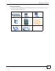
Document Conventions Icons Used in Figures Figures in this User’s Guide may use the following generic icons. The Switch icon is not an exact representation of your device.
Safety Warnings Safety Warnings 1 For your safety, be sure to read and follow all warning notices and instructions. • Do NOT use this product near water, for example, in a wet basement or near a swimming pool. • Do NOT expose your device to dampness, dust or corrosive liquids. • Do NOT store things on the device. • Do NOT install, use, or service this device during a thunderstorm. There is a remote risk of electric shock from lightning. • Connect ONLY suitable accessories to the device.
Safety Warnings GS-3012/GS-3012F User’s Guide 7
Safety Warnings 8 GS-3012/GS-3012F User’s Guide
Contents Overview Contents Overview Introduction and Hardware ................................................................................................... 29 Getting to Know Your Switch ..................................................................................................... 31 Basic Configuration ............................................................................................................... 35 Hardware Installation and Connection ........................................
Contents Overview Access Control ........................................................................................................................ 233 Diagnostic ................................................................................................................................ 251 Syslog ...................................................................................................................................... 253 Cluster Management .............................................
Table of Contents Table of Contents About This User's Guide .......................................................................................................... 3 Document Conventions............................................................................................................ 4 Safety Warnings........................................................................................................................ 6 Contents Overview .......................................................
Table of Contents Chapter 3 Hardware Overview................................................................................................................. 41 3.1 Front Panel ......................................................................................................................... 41 3.1.1 Console Port .............................................................................................................. 42 3.1.2 Gigabit Ports .......................................................
Table of Contents 7.4 Introduction to VLANs ........................................................................................................ 73 7.5 Switch Setup Screen ........................................................................................................ 73 7.6 IP Setup .............................................................................................................................. 75 7.6.1 Management IP Addresses .....................................................
Table of Contents 11.1.3 STP Port States ..................................................................................................... 101 11.1.4 Multiple RSTP ...................................................................................................... 101 11.1.5 Multiple STP ........................................................................................................... 102 11.2 Spanning Tree Protocol Status Screen .............................................................
Table of Contents 16.2.2 Activate MAC Authentication ................................................................................. 134 Chapter 17 Port Security.......................................................................................................................... 137 17.1 About Port Security ......................................................................................................... 137 17.2 Port Security Setup .............................................................
Table of Contents 21.6.2 MVR Modes ........................................................................................................... 162 21.6.3 How MVR Works .................................................................................................... 162 21.7 General MVR Configuration ............................................................................................ 162 21.8 MVR Group Configuration ..................................................................................
Table of Contents Chapter 25 Two Rate Three Color Marker .............................................................................................. 207 25.1 DiffServ Overview ........................................................................................................... 207 25.1.1 DSCP and Per-Hop Behavior ................................................................................ 207 25.1.2 DiffServ Network Example ......................................................................
Table of Contents 28.6 Restore a Configuration File ......................................................................................... 230 28.7 Backup a Configuration File ......................................................................................... 230 28.8 FTP Command Line ........................................................................................................ 231 28.8.1 Filename Conventions ............................................................................
Table of Contents 32.1 Cluster Management Status Overview ........................................................................... 257 32.2 Cluster Management Status ........................................................................................... 258 32.2.1 Cluster Member Switch Management ................................................................... 259 32.3 Clustering Management Configuration ..........................................................................
Table of Contents 20 GS-3012/GS-3012F User’s Guide
List of Figures List of Figures Figure 1 Backbone Application .............................................................................................................. 32 Figure 2 Bridging Application ................................................................................................................ 32 Figure 3 High Performance Switched Workgroup Application ............................................................... 33 Figure 4 Shared Server Using VLAN Example .......................
List of Figures Figure 39 Advanced Application > VLAN > VLAN Port Setting ............................................................. 89 Figure 40 Subnet Based VLAN Application Example ............................................................................ 90 Figure 41 Advanced Application > VLAN > VLAN Port Setting > Subnet Based VLAN ........................ 91 Figure 42 Port Based VLAN Setup (All Connected) ..............................................................................
List of Figures Figure 82 Advanced Application > Multicast > Multicast Setting > IGMP Snooping VLAN ................. 159 Figure 83 Advanced Application > Multicast > Multicast Setting > IGMP Filtering Profile ................... 160 Figure 84 MVR Network Example ....................................................................................................... 161 Figure 85 MVR Multicast Television Example .....................................................................................
List of Figures Figure 125 Global DHCP Relay Network Example ............................................................................. 222 Figure 126 DHCP Relay Configuration Example ................................................................................. 222 Figure 127 IP Application > DHCP > VLAN ....................................................................................... 223 Figure 128 DHCP Relay for Two VLANs .....................................................................
List of Tables List of Tables Table 1 Front Panel Connections .......................................................................................................... 42 Table 2 LED Descriptions ...................................................................................................................... 46 Table 3 Navigation Panel Sub-links Overview ....................................................................................... 51 Table 4 Web Configurator Screen Sub-links Details .......
List of Tables Table 39 Advanced Application > Port Authentication > 802.1x .......................................................... 134 Table 40 Advanced Application > Port Authentication > MAC Authentication ..................................... 135 Table 41 Advanced Application > Port Security ................................................................................... 138 Table 42 Advanced Application > Classifier .................................................................................
List of Tables Table 82 IP Application > DHCP > Global ........................................................................................... 221 Table 83 IP Application > DHCP > VLAN ............................................................................................ 223 Table 84 Management > Maintenance ................................................................................................ 227 Table 85 Filename Conventions .............................................................
List of Tables 28 GS-3012/GS-3012F User’s Guide
P ART I Introduction and Hardware Getting to Know Your Switch (31) Hardware Installation and Connection (37) Hardware Overview (41) 29
CHAPTER 1 Getting to Know Your Switch This chapter introduces the main features and applications of the Switch. 1.1 Introduction The GS-3012 and GS-3012F are layer 2 stand-alone Gigabit Ethernet switches. The GS-3012 has 12 100/1000 Mbps RJ-45 ports and four mini-GBIC slots for optical uplinking. There are two GS-3012 models. The GS-3012 DC model requires DC power supply input of -48 VDC to -60 VDC, 1.5A Max. The GS-3012 AC model requires 100~240VAC/ 1.5A power.
Chapter 1 Getting to Know Your Switch Figure 1 Backbone Application 1.1.2 Bridging Example In this example application the Switch connects different company departments (RD and Sales) to the corporate backbone. It can alleviate bandwidth contention and eliminate server and network bottlenecks. All users that need high bandwidth can connect to high-speed department servers via the Switch. You can provide a super-fast uplink connection by using a Gigabit Ethernet/mini-GBIC port on the Switch.
Chapter 1 Getting to Know Your Switch Switching to higher-speed LANs such as ATM (Asynchronous Transmission Mode) is not feasible for most people due to the expense of replacing all existing Ethernet cables and adapter cards, restructuring your network and complex maintenance. The Switch can provide the same bandwidth as ATM at much lower cost while still being able to use existing adapters and switches.
Chapter 1 Getting to Know Your Switch Figure 4 Shared Server Using VLAN Example 1.2 Ways to Manage the Switch Use any of the following methods to manage the Switch. • Web Configurator. This is recommended for everyday management of the Switch using a (supported) web browser. See Chapter 4 on page 49. • Command Line Interface. Line commands offer an alternative to the web configurator and in some cases are necessary to configure advanced features. See the CLI Reference Guide. • FTP.
P ART II Basic Configuration The Web Configurator (49) Initial Setup Example (59) System Status and Port Statistics (63) Basic Setting (69) 35
CHAPTER 2 Hardware Installation and Connection This chapter shows you how to install and connect the Switch. 2.1 Installation Scenarios The Switch can be placed on a desktop or rack-mounted on a standard EIA rack. Use the rubber feet in a desktop installation and the brackets in a rack-mounted installation. " For proper ventilation, allow at least 4 inches (10 cm) of clearance at the front and 3.4 inches (8 cm) at the back of the Switch. This is especially important for enclosed rack installations. 2.
Chapter 2 Hardware Installation and Connection Figure 5 " Attaching Rubber Feet Do NOT block the ventilation holes. Leave space between devices when stacking. 2.3 Mounting the Switch on a Rack The Switch can be mounted on an EIA standard size, 19-inch rack or in a wiring closet with other equipment. Follow the steps below to mount your Switch on a standard EIA rack using a rack-mounting kit. 2.3.1 Rack-mounted Installation Requirements • Two mounting brackets.
Chapter 2 Hardware Installation and Connection Figure 6 Attaching the Mounting Brackets 2 Using a #2 Philips screwdriver, install the M3 flat head screws through the mounting bracket holes into the Switch. 3 Repeat steps 1 and 2 to install the second mounting bracket on the other side of the Switch. 4 You may now mount the Switch on a rack. Proceed to the next section. 2.3.
Chapter 2 Hardware Installation and Connection 40 GS-3012/GS-3012F User’s Guide
CHAPTER 3 Hardware Overview This chapter describes the front panel and rear panel of the Switch and shows you how to make the hardware connections. 3.1 Front Panel The following figure shows the front panel of the GS-3012. The front panel contains the Switch LEDs, 8 RJ-45 gigabit ports, four dual personality interfaces each consisting of a miniGBIC slot and an RJ-45 gigabit port as well as a console and management port for local management.
Chapter 3 Hardware Overview The following table describes the port labels on the front panel. Table 1 Front Panel Connections LABEL DESCRIPTION 8 100/1000 Mbps RJ-45 Ethernet Ports (GS-3012) Connect these 1Gbps Electrical Ethernet ports to high-bandwidth backbone network Ethernet switches or use them to daisy-chain other switches. 8 Mini-GBIC Slots (GS3012F) Use mini-GBIC transceivers in these slots for fiber-optic connections to backbone Ethernet switches.
Chapter 3 Hardware Overview Four of the 1000Base-T Ethernet ports are paired with a mini-GBIC slot to create a dual personality interface. The Switch uses up to one connection for each mini-GBIC and 1000Base-T Ethernet pair. The mini-GBIC slots have priority over the Gigabit ports. This means that if a mini-GBIC slot and the corresponding Gigabit port are connected at the same time, the Gigabit port will be disabled.
Chapter 3 Hardware Overview 3.1.3.1 Transceiver Installation Use the following steps to install a mini-GBIC transceiver (SFP module). 1 Insert the transceiver into the slot with the exposed section of PCB board facing down. 2 Press the transceiver firmly until it clicks into place. 3 The Switch automatically detects the installed transceiver. Check the LEDs to verify that it is functioning properly. 4 Close the transceiver’s latch (latch styles vary). 5 Connect the fiber optic cables to the transceiver.
Chapter 3 Hardware Overview Figure 14 Transceiver Removal Example 3.1.4 Management Port The MGMT (management) port is used for local management. Connect directly to this port using an Ethernet cable. You can configure the Switch via Telnet or the web configurator. The default IP address of the management port is 192.168.0.1 with a subnet mask of 255.255.255.0. 3.2 Rear Panel The following figures show the rear panels of the GS-3012 AC and DC power models followed by the GS-3012F AC and DC power models.
Chapter 3 Hardware Overview To connect the power to the AC power model, insert the female end of power cord to the power receptacle on the rear panel. Connect the other end of the supplied power cord to a 100~240VAC/1.5A power outlet. Make sure that no objects obstruct the airflow of the fans (located on the side of the unit). The DC power models require DC power supply input of –48 VDC to -60 VDC. The GS-3012 DC power model requires 1.5A Max. The GS-3012F DC power model requires 1.25A Max.
Chapter 3 Hardware Overview Table 2 LED Descriptions (continued) LED COLOR STATUS DESCRIPTION 1000 (GS3012F) Green Blinking The system is transmitting/receiving to/from an Ethernet network. On The link to a 1000 Mbps Ethernet network is up. Off The link to a 1000 Mbps Ethernet network is down. Blinking The system is transmitting/receiving to/from an Ethernet network. On The link to a 100 Mbps Ethernet network is up. Off The link to a 100 Mbps Ethernet network is down.
Chapter 3 Hardware Overview 48 GS-3012/GS-3012F User’s Guide
CHAPTER 4 The Web Configurator This section introduces the configuration and functions of the web configurator. 4.1 Introduction The web configurator is an HTML-based management interface that allows easy Switch setup and management via Internet browser. Use Internet Explorer 6.0 and later or Netscape Navigator 7.0 and later versions. The recommended screen resolution is 1024 by 768 pixels. In order to use the web configurator you need to allow: • Web browser pop-up windows from your device.
Chapter 4 The Web Configurator Figure 19 Web Configurator: Login 4 Click OK to view the first web configurator screen. 4.3 The Status Screen The Status screen is the first screen that displays when you access the web configurator. The following figure shows the navigating components of a web configurator screen. Figure 20 Web Configurator Home Screen (Status) B C DE A A - Click the menu items to open submenu links, and then click on a submenu link to open the screen in the main window.
Chapter 4 The Web Configurator E - Click this link to display web help pages. The help pages provide descriptions for all of the configuration screens. In the navigation panel, click a main link to reveal a list of submenu links.
Chapter 4 The Web Configurator The following table lists the various web configurator screens within the sub-links.
Chapter 4 The Web Configurator The following table describes the links in the navigation panel. Table 5 Navigation Panel Links LINK DESCRIPTION Basic Settings System Info This link takes you to a screen that displays general system and hardware monitoring information. General Setup This link takes you to a screen where you can configure general identification information about the Switch.
Chapter 4 The Web Configurator Table 5 Navigation Panel Links (continued) LINK DESCRIPTION IP Source Guard This link takes you to screens where you can configure filtering of unauthorized DHCP and ARP packets in your network. Loop Guard This link takes you to a screen where you can configure protection against network loops that occur on the edge of your network. trTCM This link takes you to a screen where you can configure Two Rate Three Color Marker settings.
Chapter 4 The Web Configurator Figure 21 Change Administrator Login Password 4.4 Saving Your Configuration When you are done modifying the settings in a screen, click Apply to save your changes back to the run-time memory. Settings in the run-time memory are lost when the Switch’s power is turned off. Click the Save link in the upper right hand corner of the web configurator to save your configuration to nonvolatile memory.
Chapter 4 The Web Configurator " Be careful not to lock yourself and others out of the Switch. If you do lock yourself out, try using out-of-band management (via the management port) to configure the Switch. 4.6 Resetting the Switch If you lock yourself (and others) from the Switch or forget the administrator password, you will need to reload the factory-default configuration file or reset the Switch back to the factory defaults. 4.6.
Chapter 4 The Web Configurator Figure 22 Resetting the Switch: Via the Console Port Bootbase Version: V3.1 | 03/08/2007 18:36:17 RAM:Size = 64 Mbytes DRAM POST: Testing: 65536K OK DRAM Test SUCCESS ! FLASH: Intel 64M ZyNOS Version: V3.80(LH.0)b4 | 05/31/2007 20:43:39 Press any key to enter debug mode within 3 seconds..................... Enter Debug Mode GS-3012> atlc Starting XMODEM upload (CRC mode).... CCCCCCCCCCCCCCCC Total 393216 bytes received. Erasing.. ...............................................
Chapter 4 The Web Configurator 58 GS-3012/GS-3012F User’s Guide
CHAPTER 5 Initial Setup Example This chapter shows how to set up the Switch for an example network. 5.1 Overview The following lists the configuration steps for the initial setup: • Create a VLAN • Set port VLAN ID • Configure the Switch IP management address 5.1.1 Creating a VLAN VLANs confine broadcast frames to the VLAN group in which the port(s) belongs. You can do this with port-based VLAN or tagged static VLAN with fixed port members.
Chapter 5 Initial Setup Example 1 Click Advanced Application > VLAN in the navigation panel and click the Static VLAN link. 2 In the Static VLAN screen, select ACTIVE, enter a descriptive name in the Name field and enter 2 in the VLAN Group ID field for the VLAN2 network. Note: The VLAN Group ID field in this screen and the VID field in the IP Setup screen refer to the same VLAN ID.
Chapter 5 Initial Setup Example Figure 25 Initial Setup Network Example: Port VID 1 Click Advanced Applications > VLAN in the navigation panel. Then click the VLAN Port Setting link. 2 Enter 2 in the PVID field for port 1 and click Apply to save your changes back to the runtime memory. Settings in the run-time memory are lost when the Switch’s power is turned off. 5.2 Configuring Switch Management IP Address The default management IP address of the Switch is 192.168.1.1.
Chapter 5 Initial Setup Example 1 Connect your computer to any Ethernet port on the Switch. Make sure your computer is in the same subnet as the Switch. 2 Open your web browser and enter 192.168.1.1 (the default IP address) in the address bar to access the web configurator. See Section 4.2 on page 49 for more information. 3 Click Basic Setting > IP Setup in the navigation panel. 4 Configure the related fields in the IP Setup screen. 5 For the VLAN2 network, enter 192.168.2.1 as the IP address and 255.255.
CHAPTER 6 System Status and Port Statistics This chapter describes the system status (web configurator home page) and port details screens. 6.1 Overview The home screen of the web configurator displays a port statistical summary with links to each port showing statistical details. 6.2 Port Status Summary To view the port statistics, click Status in all web configurator screens to display the Status screen as shown next. Figure 27 Status The following table describes the labels in this screen.
Chapter 6 System Status and Port Statistics Table 6 Status (continued) LABEL DESCRIPTION Link This field displays the speed (either 10M for 10Mbps, 100M for 100Mbps or 1000M for 1000Mbps) and the duplex (F for full duplex or H for half). It also shows the cable type (Copper or Fiber) for the combo ports. State If STP (Spanning Tree Protocol) is enabled, this field displays the STP state of the port (see Section 11.1 on page 99 for more information).
Chapter 6 System Status and Port Statistics Figure 28 Status > Port Details The following table describes the labels in this screen. Table 7 Status: Port Details LABEL DESCRIPTION Port Info Port NO. This field displays the port number you are viewing. Name This field displays the name of the port. Link This field displays the speed (either 10M for 10Mbps, 100M for 100Mbps or 1000M for 1000Mbps) and the duplex (F for full duplex or H for half duplex). It also shows the cable type (Copper or Fiber).
Chapter 6 System Status and Port Statistics Table 7 Status: Port Details (continued) LABEL Up Time DESCRIPTION This field shows the total amount of time the connection has been up. Tx Packet The following fields display detailed information about packets transmitted. TX Packet This field shows the number of good packets (unicast, multicast and broadcast) transmitted. Multicast This field shows the number of good multicast packets transmitted.
Chapter 6 System Status and Port Statistics Table 7 Status: Port Details (continued) LABEL DESCRIPTION 512-1023 This field shows the number of packets (including bad packets) received that were between 512 and 1023 octets in length. 10241518 This field shows the number of packets (including bad packets) received that were between 1024 and 1518 octets in length. Giant This field shows the number of packets dropped because they were bigger than the maximum frame size.
Chapter 6 System Status and Port Statistics 68 GS-3012/GS-3012F User’s Guide
CHAPTER 7 Basic Setting This chapter describes how to configure the System Info, General Setup, Switch Setup, IP Setup and Port Setup screens. 7.1 Overview The System Info screen displays general Switch information (such as firmware version number) and hardware polling information (such as fan speeds). The General Setup screen allows you to configure general Switch identification information.
Chapter 7 Basic Setting Figure 29 Basic Setting > System Info The following table describes the labels in this screen. Table 8 Basic Setting > System Info LABEL DESCRIPTION System Name This field displays the descriptive name of the Switch for identification purposes. ZyNOS F/W Version This field displays the version number of the Switch 's current firmware including the date created. Ethernet Address This field refers to the Ethernet MAC (Media Access Control) address of the Switch.
Chapter 7 Basic Setting Table 8 Basic Setting > System Info (continued) LABEL DESCRIPTION Current This field displays this fan's current speed in Revolutions Per Minute (RPM). MAX This field displays this fan's maximum speed measured in Revolutions Per Minute (RPM). MIN This field displays this fan's minimum speed measured in Revolutions Per Minute (RPM). "<41" is displayed for speeds too small to measure (under 2000 RPM).
Chapter 7 Basic Setting The following table describes the labels in this screen. Table 9 Basic Setting > General Setup 72 LABEL DESCRIPTION System Name Choose a descriptive name for identification purposes. This name consists of up to 64 printable characters; spaces are allowed. Location Enter the geographic location of your Switch. You can use up to 32 printable ASCII characters; spaces are allowed. Contact Person's Name Enter the name of the person in charge of this Switch.
Chapter 7 Basic Setting Table 9 Basic Setting > General Setup (continued) LABEL DESCRIPTION End Date Configure the day and time when Daylight Saving Time ends if you selected Daylight Saving Time. The time field uses the 24 hour format. Here are a couple of examples: Daylight Saving Time ends in the United States on the first Sunday of November. Each time zone in the United States stops using Daylight Saving Time at 2 A.M. local time.
Chapter 7 Basic Setting Figure 31 Basic Setting > Switch Setup The following table describes the labels in this screen. Table 10 Basic Setting > Switch Setup LABEL DESCRIPTION VLAN Type Choose 802.1Q or Port Based. The VLAN Setup screen changes depending on whether you choose 802.1Q VLAN type or Port Based VLAN type in this screen. See Chapter 8 on page 83 for more information.
Chapter 7 Basic Setting Table 10 Basic Setting > Switch Setup (continued) LABEL DESCRIPTION Priority Queue Assignment IEEE 802.1p defines up to eight separate traffic types by inserting a tag into a MAC-layer frame that contains bits to define class of service. Frames without an explicit priority tag are given the default priority of the ingress port. Use the next fields to configure the priority level-to-physical queue mapping.
Chapter 7 Basic Setting Figure 32 Basic Setting > IP Setup The following table describes the labels in this screen. Table 11 Basic Setting > IP Setup LABEL DESCRIPTION Domain Name Server DNS (Domain Name System) is for mapping a domain name to its corresponding IP address and vice versa. Enter a domain name server IP address in order to be able to use a domain name instead of an IP address.
Chapter 7 Basic Setting Table 11 Basic Setting > IP Setup (continued) LABEL DESCRIPTION IP Address Enter the IP address of your Switch in dotted decimal notation for example 192.168.1.1. IP Subnet Mask Enter the IP subnet mask of your Switch in dotted decimal notation for example 255.255.255.0. Default Gateway Enter the IP address of the default outgoing gateway in dotted decimal notation, for example 192.168.1.254. VID Enter the VLAN identification number associated with the Switch IP address.
Chapter 7 Basic Setting Table 11 Basic Setting > IP Setup (continued) LABEL DESCRIPTION Delete Check the management IP addresses that you want to remove in the Delete column, then click the Delete button. Cancel Click Cancel to clear the selected checkboxes in the Delete column. 7.7 Port Setup Use this screen to configure Switch port settings.Click Basic Setting > Port Setup in the navigation panel to display the configuration screen.
Chapter 7 Basic Setting Table 12 Basic Setting > Port Setup (continued) LABEL DESCRIPTION Speed/Duplex Select the speed and the duplex mode of the Ethernet connection on this port. Choices are Auto, 10M/Half Duplex, 10M/Full Duplex, 100M/Half Duplex, 100M/ Full Duplex and 1000M/Full Duplex. Selecting Auto (auto-negotiation) allows one port to negotiate with a peer port automatically to obtain the connection speed and duplex mode that both ends support.
Chapter 7 Basic Setting 80 GS-3012/GS-3012F User’s Guide
P ART III Advanced VLAN (83) Static MAC Forward Setup (95) Filtering (97) Spanning Tree Protocol (99) Bandwidth Control (117) Broadcast Storm Control (119) Mirroring (121) Link Aggregation (123) Port Authentication (131) Port Security (137) Classifier (141) Policy Rule (147) Queuing Method (153) Multicast (155) Authentication & Accounting (169) IP Source Guard (183) Loop Guard (203) Two Rate Three Color Marker (207) 81
CHAPTER 8 VLAN The type of screen you see here depends on the VLAN Type you selected in the Switch Setup screen. This chapter shows you how to configure 802.1Q tagged and port-based VLANs. 8.1 Introduction to IEEE 802.1Q Tagged VLANs A tagged VLAN uses an explicit tag (VLAN ID) in the MAC header to identify the VLAN membership of a frame across bridges - they are not confined to the switch on which they were created. The VLANs can be created statically by hand or dynamically through GVRP.
Chapter 8 VLAN 8.2 Automatic VLAN Registration GARP and GVRP are the protocols used to automatically register VLAN membership across switches. 8.2.1 GARP GARP (Generic Attribute Registration Protocol) allows network switches to register and deregister attribute values with other GARP participants within a bridged LAN. GARP is a protocol that provides a generic mechanism for protocols that serve a more specific application, for example, GVRP. 8.2.1.1 GARP Timers Switches join VLANs by making a declaration.
Chapter 8 VLAN 8.3 Port VLAN Trunking Enable VLAN Trunking on a port to allow frames belonging to unknown VLAN groups to pass through that port. This is useful if you want to set up VLAN groups on end devices without having to configure the same VLAN groups on intermediary devices. Refer to the following figure. Suppose you want to create VLAN groups 1 and 2 (V1 and V2) on devices A and B.
Chapter 8 VLAN 8.5.1 Static VLAN Status See Section 8.1 on page 83 for more information on Static VLAN. Click Advanced Application > VLAN from the navigation panel to display the VLAN Status screen as shown next. Figure 36 Advanced Application > VLAN: VLAN Status The following table describes the labels in this screen. Table 14 Advanced Application > VLAN: VLAN Status LABEL DESCRIPTION The Number of VLAN This is the number of VLANs configured on the Switch. Index This is the VLAN index number.
Chapter 8 VLAN The following table describes the labels in this screen. Table 15 Advanced Application > VLAN > VLAN Detail LABEL DESCRIPTION VLAN Status Click this to go to the VLAN Status screen. VID This is the VLAN identification number that was configured in the Static VLAN screen. Port Number This column displays the ports that are participating in a VLAN. A tagged port is marked as T, an untagged port is marked as U and ports not participating in a VLAN are marked as “–“.
Chapter 8 VLAN The following table describes the related labels in this screen. Table 16 Advanced Application > VLAN > Static VLAN LABEL DESCRIPTION ACTIVE Select this check box to activate the VLAN settings. Name Enter a descriptive name for the VLAN group for identification purposes. This name consists of up to 64 printable characters. VLAN Group ID Enter the VLAN ID for this static entry; the valid range is between 1 and 4094. Port The port number identifies the port you are configuring.
Chapter 8 VLAN Figure 39 Advanced Application > VLAN > VLAN Port Setting The following table describes the labels in this screen. Table 17 Advanced Application > VLAN > VLAN Port Setting LABEL DESCRIPTION GVRP GVRP (GARP VLAN Registration Protocol) is a registration protocol that defines a way for switches to register necessary VLAN members on ports across the network. Select this check box to permit VLAN groups beyond the local Switch.
Chapter 8 VLAN Table 17 Advanced Application > VLAN > VLAN Port Setting (continued) LABEL DESCRIPTION Apply Click Apply to save your changes to the Switch’s run-time memory. The Switch loses these changes if it is turned off or loses power, so use the Save link on the top navigation panel to save your changes to the non-volatile memory when you are done configuring. Cancel Click Cancel to begin configuring this screen afresh. 8.
Chapter 8 VLAN 8.7 Configuring Subnet Based VLAN Click Subnet Based VLAN in the VLAN Port Setting screen to display the configuration screen as shown. " Subnet based VLAN applies to un-tagged packets and is applicable only when you use IEEE 802.1Q tagged VLAN. Figure 41 Advanced Application > VLAN > VLAN Port Setting > Subnet Based VLAN The following table describes the labels in this screen.
Chapter 8 VLAN Table 18 Advanced Application > VLAN > VLAN Port Setting > Subnet Based VLAN Setup LABEL DESCRIPTION Mask-Bits Enter the bit number of the subnet mask. To find the bit number, convert the subnet mask to binary format and add all the 1’s together. Take “255.255.255.0” for example. 255 converts to eight 1s in binary. There are three 255s, so add three eights together and you get the bit number (24).
Chapter 8 VLAN " In screens (such as IP Setup and Filtering) that require a VID, you must enter 1 as the VID. The port-based VLAN setup screen is shown next. The CPU management port forms a VLAN with all Ethernet ports. 8.8.1 Configure a Port-based VLAN Select Port Based as the VLAN Type in the Basic Setting > Switch Setup screen and then click Advanced Application > VLAN from the navigation panel to display the next screen.
Chapter 8 VLAN Figure 43 Port Based VLAN Setup (Port Isolation) The following table describes the labels in this screen. Table 19 Port Based VLAN Setup label Description Setting Wizard Choose All connected or Port isolation. All connected means all ports can communicate with each other, that is, there are no virtual LANs. All incoming and outgoing ports are selected. This option is the most flexible but also the least secure.
CHAPTER 9 Static MAC Forward Setup Use these screens to configure static MAC address forwarding. 9.1 Overview This chapter discusses how to configure forwarding rules based on MAC addresses of devices on your network. 9.2 Configuring Static MAC Forwarding A static MAC address is an address that has been manually entered in the MAC address table. Static MAC addresses do not age out. When you set up static MAC address rules, you are setting static MAC addresses for a port.
Chapter 9 Static MAC Forward Setup The following table describes the labels in this screen. Table 20 Advanced Application > Static MAC Forwarding LABEL DESCRIPTION Active Select this check box to activate your rule. You may temporarily deactivate a rule without deleting it by clearing this check box. Name Enter a descriptive name for identification purposes for this static MAC address forwarding rule.
CHAPTER 10 Filtering This chapter discusses MAC address port filtering. 10.1 Configure a Filtering Rule Filtering means sifting traffic going through the Switch based on the source and/or destination MAC addresses and VLAN group (ID). Click Advanced Application > Filtering in the navigation panel to display the screen as shown next. Figure 45 Advanced Application > Filtering The following table describes the related labels in this screen.
Chapter 10 Filtering Table 21 Advanced Application > FIltering (continued) 98 LABEL DESCRIPTION Action Select Discard source to drop the frames from the source MAC address (specified in the MAC field). The Switch can still send frames to the MAC address. Select Discard destination to drop the frames to the destination MAC address (specified in the MAC address). The Switch can still receive frames originating from the MAC address.
CHAPTER 11 Spanning Tree Protocol The Switch supports Spanning Tree Protocol (STP), Rapid Spanning Tree Protocol (RSTP) and Multiple Spanning Tree Protocol (MSTP) as defined in the following standards. • IEEE 802.1D Spanning Tree Protocol • IEEE 802.1w Rapid Spanning Tree Protocol • IEEE 802.1s Multiple Spanning Tree Protocol The Switch also allows you to set up multiple STP configurations (or trees). Ports can then be assigned to the trees. 11.
Chapter 11 Spanning Tree Protocol Path cost is the cost of transmitting a frame onto a LAN through that port. The recommended cost is assigned according to the speed of the link to which a port is attached. The slower the media, the higher the cost.
Chapter 11 Spanning Tree Protocol 11.1.3 STP Port States STP assigns five port states to eliminate packet looping. A bridge port is not allowed to go directly from blocking state to forwarding state so as to eliminate transient loops. Table 23 STP Port States PORT STATE DESCRIPTION Disabled STP is disabled (default). Blocking Only configuration and management BPDUs are received and processed. Listening All BPDUs are received and processed. Note: The listening state does not exist in RSTP.
Chapter 11 Spanning Tree Protocol 11.1.5 Multiple STP Multiple Spanning Tree Protocol (IEEE 802.1s) is backward compatible with STP/RSTP and addresses the limitations of existing spanning tree protocols (STP and RSTP) in networks to include the following features: • One Common and Internal Spanning Tree (CIST) that represents the entire network’s connectivity. • Grouping of multiple bridges (or switching devices) into regions that appear as one single bridge on the network.
Chapter 11 Spanning Tree Protocol Figure 48 MSTP Network Example A VLAN 1 VLAN 2 B 11.1.5.2 MST Region An MST region is a logical grouping of multiple network devices that appears as a single device to the rest of the network. Each MSTP-enabled device can only belong to one MST region. When BPDUs enter an MST region, external path cost (of paths outside this region) is increased by one. Internal path cost (of paths within this region) is increased by one when BPDUs traverse the region.
Chapter 11 Spanning Tree Protocol Figure 49 MSTIs in Different Regions 11.1.5.4 Common and Internal Spanning Tree (CIST) A CIST represents the connectivity of the entire network and it is equivalent to a spanning tree in an STP/RSTP. The CIST is the default MST instance (MSTID 0). Any VLANs that are not members of an MST instance are members of the CIST. In an MSTP-enabled network, there is only one CIST that runs between MST regions and single spanning tree devices.
Chapter 11 Spanning Tree Protocol Figure 51 Advanced Application > Spanning Tree Protocol This screen differs depending on which STP mode (RSTP, MRSTP or MSTP) you configure on the Switch. This screen is described in detail in the section that follows the configuration section for each STP mode. Click Configuration to activate one of the STP standards on the Switch. 11.3 Spanning Tree Configuration Use the Spanning Tree Configuration screen to activate one of the STP modes on the Switch.
Chapter 11 Spanning Tree Protocol 11.4 Configure Rapid Spanning Tree Protocol Use this screen to configure RSTP settings, see Section 11.1 on page 99 for more information on RSTP. Click RSTP in the Advanced Application > Spanning Tree Protocol screen. Figure 53 Advanced Application > Spanning Tree Protocol > RSTP The following table describes the labels in this screen.
Chapter 11 Spanning Tree Protocol Table 25 Advanced Application > Spanning Tree Protocol > RSTP (continued) LABEL DESCRIPTION Hello Time This is the time interval in seconds between BPDU (Bridge Protocol Data Units) configuration message generations by the root switch. The allowed range is 1 to 10 seconds. Max Age This is the maximum time (in seconds) the Switch can wait without receiving a BPDU before attempting to reconfigure.
Chapter 11 Spanning Tree Protocol " This screen is only available after you activate RSTP on the Switch. Figure 54 Advanced Application > Spanning Tree Protocol > Status: RSTP The following table describes the labels in this screen. Table 26 Advanced Application > Spanning Tree Protocol > Status: RSTP LABEL DESCRIPTION Configuration Click Configuration to specify which STP mode you want to activate. Click RSTP to edit RSTP settings on the Switch.
Chapter 11 Spanning Tree Protocol 11.6 Configure Multiple Rapid Spanning Tree Protocol To configure MRSTP, click MRSTP in the Advanced Application > Spanning Tree Protocol screen. See Section 11.1 on page 99 for more information on MRSTP. Figure 55 Advanced Application > Spanning Tree Protocol > MRSTP The following table describes the labels in this screen.
Chapter 11 Spanning Tree Protocol Table 27 Advanced Application > Spanning Tree Protocol > MRSTP (continued) LABEL DESCRIPTION Max Age This is the maximum time (in seconds) the Switch can wait without receiving a BPDU before attempting to reconfigure. All Switch ports (except for designated ports) should receive BPDUs at regular intervals. Any port that ages out STP information (provided in the last BPDU) becomes the designated port for the attached LAN.
Chapter 11 Spanning Tree Protocol Figure 56 Advanced Application > Spanning Tree Protocol > Status: MRSTP The following table describes the labels in this screen. Table 28 Advanced Application > Spanning Tree Protocol > Status: MRSTP LABEL DESCRIPTION Configuration Click Configuration to specify which STP mode you want to activate. Click MRSTP to edit MRSTP settings on the Switch. Tree Select which STP tree configuration you want to view.
Chapter 11 Spanning Tree Protocol Figure 57 Advanced Application > Spanning Tree Protocol > MSTP 112 GS-3012/GS-3012F User’s Guide
Chapter 11 Spanning Tree Protocol The following table describes the labels in this screen. Table 29 Advanced Application > Spanning Tree Protocol > MSTP LABEL DESCRIPTION Status Click Status to display the MSTP Status screen (see Figure 58 on page 115). Active Select this check box to activate MSTP on the Switch. Clear this checkbox to disable MSTP on the Switch.
Chapter 11 Spanning Tree Protocol Table 29 Advanced Application > Spanning Tree Protocol > MSTP (continued) LABEL DESCRIPTION VLAN Range Enter the start of the VLAN ID range that you want to add or remove from the VLAN range edit area in the Start field. Enter the end of the VLAN ID range that you want to add or remove from the VLAN range edit area in the End field. Next click: • Add - to add this range of VLAN(s) to be mapped to the MST instance.
Chapter 11 Spanning Tree Protocol " This screen is only available after you activate MSTP on the Switch. Figure 58 Advanced Application > Spanning Tree Protocol > Status: MSTP The following table describes the labels in this screen. Table 30 Advanced Application > Spanning Tree Protocol > Status: MSTP LABEL DESCRIPTION Configuration Click Configuration to specify which STP mode you want to activate. Click MSTP to edit MSTP settings on the Switch.
Chapter 11 Spanning Tree Protocol Table 30 Advanced Application > Spanning Tree Protocol > Status: MSTP (continued) 116 LABEL DESCRIPTION Forwarding Delay (second) This is the time (in seconds) the root switch will wait before changing states (that is, listening to learning to forwarding). Cost to Bridge This is the path cost from the root port on this Switch to the root switch.
CHAPTER 12 Bandwidth Control This chapter shows you how you can cap the maximum bandwidth using the Bandwidth Control screen. 12.1 Bandwidth Control Overview Bandwidth control means defining a maximum allowable bandwidth for incoming and/or outgoing traffic flows on a port. 12.1.1 CIR and PIR The Committed Information Rate (CIR) is the guaranteed bandwidth for the incoming traffic flow on a port.
Chapter 12 Bandwidth Control Figure 59 Advanced Application > Bandwidth Control The following table describes the related labels in this screen. Table 31 Advanced Application > Bandwidth Control LABEL DESCRIPTION Active Select this check box to enable bandwidth control on the Switch. Port This field displays the port number. * Settings in this row apply to all ports. Use this row only if you want to make some settings the same for all ports.
CHAPTER 13 Broadcast Storm Control This chapter introduces and shows you how to configure the broadcast storm control feature. 13.1 Broadcast Storm Control Setup Broadcast storm control limits the number of broadcast, multicast and destination lookup failure (DLF) packets the Switch receives per second on the ports. When the maximum number of allowable broadcast, multicast and/or DLF packets is reached per second, the subsequent packets are discarded.
Chapter 13 Broadcast Storm Control The following table describes the labels in this screen. Table 32 Advanced Application > Broadcast Storm Control LABEL DESCRIPTION Active Select this check box to enable traffic storm control on the Switch. Clear this check box to disable this feature. Port This field displays the port number. * Settings in this row apply to all ports. Use this row only if you want to make some settings the same for all ports.
CHAPTER 14 Mirroring This chapter discusses port mirroring setup screens. 14.1 Port Mirroring Setup Port mirroring allows you to copy a traffic flow to a monitor port (the port you copy the traffic to) in order that you can examine the traffic from the monitor port without interference. Click Advanced Application > Mirroring in the navigation panel to display the Mirroring screen. Use this screen to select a monitor port and specify the traffic flow to be copied to the monitor port.
Chapter 14 Mirroring The following table describes the labels in this screen. Table 33 Advanced Application > Mirroring LABEL DESCRIPTION Active Select this check box to activate port mirroring on the Switch. Clear this check box to disable the feature. Monitor Port The monitor port is the port you copy the traffic to in order to examine it in more detail without interfering with the traffic flow on the original port(s). Enter the port number of the monitor port.
CHAPTER 15 Link Aggregation This chapter shows you how to logically aggregate physical links to form one logical, higherbandwidth link. 15.1 Link Aggregation Overview Link aggregation (trunking) is the grouping of physical ports into one logical higher-capacity link. You may want to trunk ports if for example, it is cheaper to use multiple lower-speed links than to under-utilize a high-speed, but more costly, single-port link. However, the more ports you aggregate then the fewer available ports you have.
Chapter 15 Link Aggregation • You must connect all ports point-to-point to the same Ethernet switch and configure the ports for LACP trunking. • LACP only works on full-duplex links. • All ports in the same trunk group must have the same media type, speed, duplex mode and flow control settings. Configure trunk groups or LACP before you connect the Ethernet switch to avoid causing network topology loops. 15.2.
Chapter 15 Link Aggregation Table 36 Advanced Application > Link Aggregation Status (continued) LABEL DESCRIPTION Synchronized Ports These are the ports that are currently transmitting data as one logical link in this trunk group. Aggregator ID Link Aggregator ID consists of the following: system priority, MAC address, key, port priority and port number. Refer to Section 15.2.1 on page 124 for more information on this field. Status This field displays how these ports were added to the trunk group.
Chapter 15 Link Aggregation The following table describes the labels in this screen. Table 37 Advanced Application > Link Aggregation > Link Aggregation Setting LABEL DESCRIPTION Link Aggregation Setting This is the only screen you need to configure to enable static link aggregation. Group ID The field identifies the link aggregation group, that is, one logical link containing multiple ports. Active Select this option to activate a trunk group. Port This field displays the port number.
Chapter 15 Link Aggregation Figure 64 Advanced Application > Link Aggregation > Link Aggregation Setting > LACP The following table describes the labels in this screen. Table 38 Advanced Application > Link Aggregation > Link Aggregation Setting > LACP LABEL Link Aggregation Control Protocol DESCRIPTION Note: Do not configure this screen unless you want to enable dynamic link aggregation. Active Select this checkbox to enable Link Aggregation Control Protocol (LACP).
Chapter 15 Link Aggregation Table 38 Advanced Application > Link Aggregation > Link Aggregation Setting > LACP LABEL DESCRIPTION * Settings in this row apply to all ports. Use this row only if you want to make some settings the same for all ports. Use this row first to set the common settings and then make adjustments on a port-by-port basis. Note: Changes in this row are copied to all the ports as soon as you make them.
Chapter 15 Link Aggregation Figure 66 Trunking Example - Configuration Screen Your trunk group 1 (T1) configuration is now complete; you do not need to go to any additional screens.
Chapter 15 Link Aggregation 130 GS-3012/GS-3012F User’s Guide
CHAPTER 16 Port Authentication This chapter describes the IEEE 802.1x and MAC authentication methods. 16.1 Port Authentication Overview Port authentication is a way to validate access to ports on the Switch to clients based on an external server (authentication server). The Switch supports the following methods for port authentication: • IEEE 802.1x2 - An authentication server validates access to a port based on a username and password provided by the user.
Chapter 16 Port Authentication Figure 67 IEEE 802.1x Authentication Process 1 New Connection 2 Login Info Request 3 Login Credentials 4 Authentication Request 5 Authentication Reply Session Granted/Denied 16.1.2 MAC Authentication MAC authentication works in a very similar way to IEEE 802.1x authentication. The main difference is that the Switch does not prompt the client for login credentials.
Chapter 16 Port Authentication 16.2 Port Authentication Configuration To enable port authentication, first activate the port authentication method(s) you want to use (both on the Switch and the port(s)) then configure the RADIUS server settings in the Auth and Acct > Radius Server Setup screen. Click Advanced Application > Port Authentication in the navigation panel to display the screen as shown. Figure 69 Advanced Application > Port Authentication 16.2.1 Activate IEEE 802.
Chapter 16 Port Authentication The following table describes the labels in this screen. Table 39 Advanced Application > Port Authentication > 802.1x LABEL DESCRIPTION Active Select this check box to permit 802.1x authentication on the Switch. Note: You must first enable 802.1x authentication on the Switch before configuring it on each port. Port This field displays the port number. * Settings in this row apply to all ports. Use this row only if you want to make some settings the same for all ports.
Chapter 16 Port Authentication Figure 71 Advanced Application > Port Authentication > MAC Authentication The following table describes the labels in this screen. Table 40 Advanced Application > Port Authentication > MAC Authentication LABEL DESCRIPTION Active Select this check box to permit MAC authentication on the Switch. Note: You must first enable MAC authentication on the Switch before configuring it on each port.
Chapter 16 Port Authentication Table 40 Advanced Application > Port Authentication > MAC Authentication (continued) LABEL DESCRIPTION * Use this row to make the setting the same for all ports. Use this row first and then make adjustments on a port-by-port basis. Note: Changes in this row are copied to all the ports as soon as you make them. 136 Active Select this checkbox to permit MAC authentication on this port.
CHAPTER 17 Port Security This chapter shows you how to set up port security. 17.1 About Port Security Port security allows only packets with dynamically learned MAC addresses and/or configured static MAC addresses to pass through a port on the Switch. The Switch can learn up to 16K MAC addresses in total with no limit on individual ports other than the sum cannot exceed 16K. For maximum port security, enable this feature, disable MAC address learning and configure static MAC address(es) for a port.
Chapter 17 Port Security Figure 72 Advanced Application > Port Security The following table describes the labels in this screen. Table 41 Advanced Application > Port Security LABEL DESCRIPTION Active Select this option to enable port security on the Switch. Port This field displays the port number. * Settings in this row apply to all ports. Use this row only if you want to make some settings the same for all ports.
Chapter 17 Port Security Table 41 Advanced Application > Port Security (continued) LABEL DESCRIPTION Apply Click Apply to save your changes to the Switch’s run-time memory. The Switch loses these changes if it is turned off or loses power, so use the Save link on the top navigation panel to save your changes to the non-volatile memory when you are done configuring. Cancel Click Cancel to begin configuring this screen afresh.
Chapter 17 Port Security 140 GS-3012/GS-3012F User’s Guide
CHAPTER 18 Classifier This chapter introduces and shows you how to configure the packet classifier on the Switch. 18.1 About the Classifier and QoS Quality of Service (QoS) refers to both a network's ability to deliver data with minimum delay, and the networking methods used to control the use of bandwidth. Without QoS, all traffic data is equally likely to be dropped when the network is congested.
Chapter 18 Classifier Figure 73 Advanced Application > Classifier The following table describes the labels in this screen. Table 42 Advanced Application > Classifier LABEL DESCRIPTION Active Select this option to enable this rule. Name Enter a descriptive name for this rule for identifying purposes. Packet Format Specify the format of the packet. Choices are All, 802.3 tagged, 802.3 untagged, Ethernet II tagged and Ethernet II untagged. A value of 802.
Chapter 18 Classifier Table 42 Advanced Application > Classifier (continued) LABEL DESCRIPTION Ethernet Type Select an Ethernet type or select Other and enter the Ethernet type number in hexadecimal value. Refer to Table 44 on page 144 for information. Source MAC Address Select Any to apply the rule to all MAC addresses. To specify a source, select the second choice and type a MAC address in valid MAC address format (six hexadecimal character pairs).
Chapter 18 Classifier Table 42 Advanced Application > Classifier (continued) LABEL DESCRIPTION Cancel Click Cancel to reset the fields back to your previous configuration. Clear Click Clear to set the above fields back to the factory defaults. 18.3 Viewing and Editing Classifier Configuration To view a summary of the classifier configuration, scroll down to the summary table at the bottom of the Classifier screen. To change the settings of a rule, click a number in the Index field.
Chapter 18 Classifier Table 44 Common Ethernet Types and Protocol Numbers ETHERNET TYPE PROTOCOL NUMBER XNS Compat 0807 Banyan Systems 0BAD BBN Simnet 5208 IBM SNA 80D5 AppleTalk AARP 80F3 In the Internet Protocol there is a field, called “Protocol”, to identify the next level protocol. The following table shows some common protocol types and the corresponding protocol number. Refer to http://www.iana.org/assignments/protocol-numbers for a complete list.
Chapter 18 Classifier Figure 75 Classifier: Example 146 GS-3012/GS-3012F User’s Guide
CHAPTER 19 Policy Rule This chapter shows you how to configure policy rules. 19.1 Policy Rules Overview A classifier distinguishes traffic into flows based on the configured criteria (refer to Chapter 18 on page 141 for more information). A policy rule ensures that a traffic flow gets the requested treatment in the network. 19.1.
Chapter 19 Policy Rule 19.2 Configuring Policy Rules You must first configure a classifier in the Classifier screen. Refer to Section 18.2 on page 141 for more information. Click Advanced Applications > Policy Rule in the navigation panel to display the screen as shown.
Chapter 19 Policy Rule The following table describes the labels in this screen. Table 47 Advanced Application > Policy Rule LABEL DESCRIPTION Active Select this option to enable the policy. Name Enter a descriptive name for identification purposes. Classifier(s) This field displays the active classifier(s) you configure in the Classifier screen. Select the classifier(s) to which this policy rule applies. To select more than one classifier, press [SHIFT] and select the choices at the same time.
Chapter 19 Policy Rule Table 47 Advanced Application > Policy Rule (continued) LABEL DESCRIPTION Outgoing Select Send the packet to the mirror port to send the packet to the mirror port. Select Send the packet to the egress port to send the packet to the egress port. Select Send the matching frames (broadcast or DLF, multicast, marked for dropping or to be sent to the CPU) to the egress port to send the broadcast, multicast, DLF, marked-to-drop or CPU frames to the egress port.
Chapter 19 Policy Rule 19.4 Policy Example The figure below shows an example Policy screen where you configure a policy to limit bandwidth and discard out-of-profile traffic on a traffic flow classified using the Example classifier (refer to Section 18.4 on page 145).
Chapter 19 Policy Rule 152 GS-3012/GS-3012F User’s Guide
CHAPTER 20 Queuing Method This chapter introduces the queuing methods supported. 20.1 Queuing Method Overview Queuing is used to help solve performance degradation when there is network congestion. Use the Queuing Method screen to configure queuing algorithms for outgoing traffic. See also Priority Queue Assignment in Switch Setup and 802.1p Priority in Port Setup for related information.
Chapter 20 Queuing Method 20.2 Configuring Queuing Click Advanced Application > Queuing Method in the navigation panel. Figure 79 Advanced Application > Queuing Method The following table describes the labels in this screen. Table 49 Advanced Application > Queuing Method 154 LABEL DESCRIPTION Port This label shows the port you are configuring. Method Select SPQ (Strict Priority Queuing) or WRR (Weighted Round Robin). Strict Priority Queuing (SPQ) services queues based on priority only.
CHAPTER 21 Multicast This chapter shows you how to configure various multicast features. 21.1 Multicast Overview Traditionally, IP packets are transmitted in one of either two ways - Unicast (1 sender to 1 recipient) or Broadcast (1 sender to everybody on the network). Multicast delivers IP packets to just a group of hosts on the network. IGMP (Internet Group Management Protocol) is a network-layer protocol used to establish membership in a multicast group - it is not used to carry user data.
Chapter 21 Multicast The Switch forwards multicast traffic destined for multicast groups (that it has learned from IGMP snooping or that you have manually configured) to ports that are members of that group. IGMP snooping generates no additional network traffic, allowing you to significantly reduce multicast traffic passing through your Switch. 21.1.4 IGMP Snooping and VLANs The Switch can perform IGMP snooping on up to 16 VLANs.
Chapter 21 Multicast Figure 81 Advanced Application > Multicast > Multicast Setting The following table describes the labels in this screen. Table 51 Advanced Application > Multicast > Multicast Setting LABEL DESCRIPTION IGMP Snooping Use these settings to configure IGMP Snooping. Active Select Active to enable IGMP Snooping to forward group multicast traffic only to ports that are members of that group.
Chapter 21 Multicast Table 51 Advanced Application > Multicast > Multicast Setting (continued) LABEL DESCRIPTION Reserved Multicast Group Multicast addresses (224.0.0.0 to 224.0.0.255) are reserved for the local scope. For examples, 224.0.0.1 is for all hosts in this subnet, 224.0.0.2 is for all multicast routers in this subnet, etc. A router will not forward a packet with the destination IP address within this range. See the IANA web site for more information.
Chapter 21 Multicast Figure 82 Advanced Application > Multicast > Multicast Setting > IGMP Snooping VLAN The following table describes the labels in this screen. Table 52 Advanced Application > Multicast > Multicast Setting > IGMP Snooping VLAN LABEL DESCRIPTION Mode Select auto to have the Switch learn multicast group membership information of any VLANs automatically. Select fixed to have the Switch only learn multicast group membership information of the VLAN(s) that you specify below.
Chapter 21 Multicast Table 52 Advanced Application > Multicast > Multicast Setting > IGMP Snooping VLAN LABEL DESCRIPTION Index This is the number of the IGMP snooping VLAN entry in the table. Name This field displays the descriptive name for this VLAN group. VID This field displays the ID number of the VLAN group. Delete Check the rule(s) that you want to remove in the Delete column, then click the Delete button. Cancel Click Cancel to clear the Delete check boxes. 21.
Chapter 21 Multicast Table 53 Advanced Application > Multicast > Multicast Setting > IGMP Filtering Profile LABEL DESCRIPTION Add Click Add to save the profile to the Switch’s run-time memory. The Switch loses these changes if it is turned off or loses power, so use the Save link on the top navigation panel to save your changes to the non-volatile memory when you are done configuring. Clear Click Clear to clear the fields to the factory defaults.
Chapter 21 Multicast 21.6.2 MVR Modes You can set your Switch to operate in either dynamic or compatible mode. In dynamic mode, the Switch sends IGMP leave and join reports to the other multicast devices (such as multicast routers or servers) in the multicast VLAN. This allows the multicast devices to update the multicast forwarding table to forward or not forward multicast traffic to the receiver ports. In compatible mode, the Switch does not send any IGMP reports.
Chapter 21 Multicast " Your Switch automatically creates a static VLAN (with the same VID) when you create a multicast VLAN in this screen. Figure 86 Advanced Application > Multicast > Multicast Setting > MVR The following table describes the related labels in this screen. Table 54 Advanced Application > Multicast > Multicast Setting > MVR LABEL DESCRIPTION Active Select this check box to enable MVR to allow one single multicast VLAN to be shared among different subscriber VLANs on the network.
Chapter 21 Multicast Table 54 Advanced Application > Multicast > Multicast Setting > MVR (continued) LABEL DESCRIPTION * Settings in this row apply to all ports. Use this row only if you want to make some settings the same for all ports. Use this row first to set the common settings and then make adjustments on a port-by-port basis. Note: Changes in this row are copied to all the ports as soon as you make them.
Chapter 21 Multicast Figure 87 Advanced Application > Multicast > Multicast Setting > MVR: Group Configuration The following table describes the labels in this screen. Table 55 Advanced Application > Multicast > Multicast Setting > MVR: Group Configuration LABEL DESCRIPTION Multicast VLAN ID Select a multicast VLAN ID (that you configured in the MVR screen) from the dropdown list box. Name Enter a descriptive name for identification purposes.
Chapter 21 Multicast Figure 88 MVR Configuration Example To configure the MVR settings on the Switch, create a multicast group in the MVR screen and set the receiver and source ports. Figure 89 MVR Configuration Example To set the Switch to forward the multicast group traffic to the subscribers, configure multicast group settings in the Group Configuration screen. The following figure shows an example where two multicast groups (News and Movie) are configured for the multicast VLAN 200.
Chapter 21 Multicast Figure 91 MVR Group Configuration Example GS-3012/GS-3012F User’s Guide 167
Chapter 21 Multicast 168 GS-3012/GS-3012F User’s Guide
CHAPTER 22 Authentication & Accounting This chapter describes how to configure authentication and accounting settings on the Switch. 22.1 Authentication, Authorization and Accounting Authentication is the process of determining who a user is and validating access to the Switch. The Switch can authenticate users who try to log in based on user accounts configured on the Switch itself.
Chapter 22 Authentication & Accounting 22.1.2 RADIUS and TACACS+ RADIUS and TACACS+ are security protocols used to authenticate users by means of an external server instead of (or in addition to) an internal device user database that is limited to the memory capacity of the device. In essence, RADIUS and TACACS+ authentication both allow you to validate an unlimited number of users from a central location. The following table describes some key differences between RADIUS and TACACS+.
Chapter 22 Authentication & Accounting Figure 94 Advanced Application > Auth and Acct > RADIUS Server Setup The following table describes the labels in this screen. Table 57 Advanced Application > Auth and Acct > RADIUS Server Setup LABEL DESCRIPTION Authentication Server Use this section to configure your RADIUS authentication settings. Mode This field is only valid if you configure multiple RADIUS servers.
Chapter 22 Authentication & Accounting Table 57 Advanced Application > Auth and Acct > RADIUS Server Setup (continued) LABEL DESCRIPTION Delete Check this box if you want to remove an existing RADIUS server entry from the Switch. This entry is deleted when you click Apply. Apply Click Apply to save your changes to the Switch’s run-time memory.
Chapter 22 Authentication & Accounting Figure 95 Advanced Application > Auth and Acct > TACACS+ Server Setup The following table describes the labels in this screen. Table 58 Advanced Application > Auth and Acct > TACACS+ Server Setup LABEL DESCRIPTION Authentication Server Use this section to configure your TACACS+ authentication settings. Mode This field is only valid if you configure multiple TACACS+ servers.
Chapter 22 Authentication & Accounting Table 58 Advanced Application > Auth and Acct > TACACS+ Server Setup (continued) LABEL DESCRIPTION Shared Secret Specify a password (up to 32 alphanumeric characters) as the key to be shared between the external TACACS+ server and the Switch. This key is not sent over the network. This key must be the same on the external TACACS+ server and the Switch. Delete Check this box if you want to remove an existing TACACS+ server entry from the Switch.
Chapter 22 Authentication & Accounting Figure 96 Advanced Application > Auth and Acct > Auth and Acct Setup The following table describes the labels in this screen. Table 59 Advanced Application > Auth and Acct > Auth and Acct Setup LABEL DESCRIPTION Authentication Use this section to specify the methods used to authenticate users accessing the Switch.
Chapter 22 Authentication & Accounting Table 59 Advanced Application > Auth and Acct > Auth and Acct Setup (continued) 176 LABEL DESCRIPTION Login These fields specify which database the Switch should use (first, second and third) to authenticate administrator accounts (users for Switch management). Configure the local user accounts in the Access Control > Logins screen. The TACACS+ and RADIUS are external servers.
Chapter 22 Authentication & Accounting Table 59 Advanced Application > Auth and Acct > Auth and Acct Setup (continued) LABEL DESCRIPTION Apply Click Apply to save your changes to the Switch’s run-time memory. The Switch loses these changes if it is turned off or loses power, so use the Save link on the top navigation panel to save your changes to the non-volatile memory when you are done configuring. Cancel Click Cancel to begin configuring this screen afresh. 22.2.
Chapter 22 Authentication & Accounting Table 60 Supported VSAs FUNCTION ATTRIBUTE Egress Bandwidth Assignment Vendor-Id = 890 Vendor-Type = 2 Vendor-data = egress rate (Kbps in decimal format) Privilege Assignment Vendor-ID = 890 Vendor-Type = 3 Vendor-Data = "shell:priv-lvl=N" or Vendor-ID = 9 (CISCO) Vendor-Type = 1 (CISCO-AVPAIR) Vendor-Data = "shell:priv-lvl=N" where N is a privilege level (from 0 to 14).
Chapter 22 Authentication & Accounting 22.3.1 Attributes Used for Authentication The following sections list the attributes sent from the Switch to the RADIUS server when performing authentication. 22.3.1.1 Attributes Used for Authenticating Privilege Access User-Name - the format of the User-Name attribute is $enab#$, where # is the privilege level (114) User-Password NAS-Identifier NAS-IP-Address 22.3.1.2 Attributes Used to Login Users User-Name User-Password NAS-Identifier NAS-IP-Address 22.3.1.
Chapter 22 Authentication & Accounting 22.3.2.
Chapter 22 Authentication & Accounting Table 64 RADIUS Attributes - Exec Events via Console ATTRIBUTE START INTERIM-UPDATE STOP NAS-Port-Type Y Y Y Acct-Status-Type Y Y Y Acct-Delay-Time Y Y Y Acct-Session-Id Y Y Y Acct-Authentic Y Y Y Acct-Input-Octets Y Y Acct-Output-Octets Y Y Acct-Session-Time Y Y Acct-Input-Packets Y Y Acct-Output-Packets Y Y Acct-Terminate-Cause Y Acct-Input-Gigawords Y Y Acct-Output-Gigawords Y Y GS-3012/GS-3012F User’s Guide 181
Chapter 22 Authentication & Accounting 182 GS-3012/GS-3012F User’s Guide
CHAPTER 23 IP Source Guard Use IP source guard to filter unauthorized DHCP and ARP packets in your network. 23.1 IP Source Guard Overview IP source guard uses a binding table to distinguish between authorized and unauthorized DHCP and ARP packets in your network. A binding contains these key attributes: • • • • MAC address VLAN ID IP address Port number When the Switch receives a DHCP or ARP packet, it looks up the appropriate MAC address, VLAN ID, IP address, and port number in the binding table.
Chapter 23 IP Source Guard Trusted ports are connected to DHCP servers or other switches. The Switch discards DHCP packets from trusted ports only if the rate at which DHCP packets arrive is too high. The Switch learns dynamic bindings from trusted ports. " The Switch will drop all DHCP requests if you enable DHCP snooping and there are no trusted ports. Untrusted ports are connected to subscribers.
Chapter 23 IP Source Guard 23.1.1.3 DHCP Relay Option 82 Information The Switch can add information to DHCP requests that it does not discard. This provides the DHCP server more information about the source of the requests. The Switch can add the following information: • Slot ID (1 byte), port ID (1 byte), and source VLAN ID (2 bytes) • System name (up to 32 bytes) This information is stored in an Agent Information field in the option 82 field of the DHCP headers of client DHCP request frames.
Chapter 23 IP Source Guard 23.1.2.1 ARP Inspection and MAC Address Filters When the Switch identifies an unauthorized ARP packet, it automatically creates a MAC address filter to block traffic from the source MAC address and source VLAN ID of the unauthorized ARP packet. You can configure how long the MAC address filter remains in the Switch. These MAC address filters are different than regular MAC address filters (Chapter 10 on page 97). • They are stored only in volatile memory.
Chapter 23 IP Source Guard 23.2 IP Source Guard Use this screen to look at the current bindings for DHCP snooping and ARP inspection. Bindings are used by DHCP snooping and ARP inspection to distinguish between authorized and unauthorized packets in the network. The Switch learns the bindings by snooping DHCP packets (dynamic bindings) and from information provided manually by administrators (static bindings). To open this screen, click Advanced Application > IP Source Guard.
Chapter 23 IP Source Guard Figure 100 IP Source Guard Static Binding The following table describes the labels in this screen. Table 66 IP Source Guard Static Binding 188 LABEL DESCRIPTION MAC Address Enter the source MAC address in the binding. IP Address Enter the IP address assigned to the MAC address in the binding. VLAN Enter the source VLAN ID in the binding. Port Specify the port(s) in the binding.
Chapter 23 IP Source Guard 23.4 DHCP Snooping Use this screen to look at various statistics about the DHCP snooping database. To open this screen, click Advanced Application > IP Source Guard > DHCP Snooping.
Chapter 23 IP Source Guard The following table describes the labels in this screen. Table 67 DHCP Snooping LABEL DESCRIPTION Database Status This section displays the current settings for the DHCP snooping database. You can configure them in the DHCP Snooping Configure screen. See Section 23.5 on page 192. Agent URL This field displays the location of the DHCP snooping database.
Chapter 23 IP Source Guard Table 67 DHCP Snooping (continued) LABEL DESCRIPTION Successful writes This field displays the number of times the Switch updated the bindings in the DHCP snooping database successfully. Failed writes This field displays the number of times the Switch was unable to update the bindings in the DHCP snooping database. Database detail First successful access This field displays the first time the Switch accessed the DHCP snooping database for any reason.
Chapter 23 IP Source Guard 23.5 DHCP Snooping Configure Use this screen to enable DHCP snooping on the Switch (not on specific VLAN), specify the VLAN where the default DHCP server is located, and configure the DHCP snooping database. The DHCP snooping database stores the current bindings on a secure, external TFTP server so that they are still available after a restart. To open this screen, click Advanced Application > IP Source Guard > DHCP Snooping > Configure.
Chapter 23 IP Source Guard Table 68 DHCP Snooping Configure (continued) LABEL DESCRIPTION Database If Timeout interval is greater than Write delay interval, it is possible that the next update is scheduled to occur before the current update has finished successfully or timed out. In this case, the Switch waits to start the next update until it completes the current one. Agent URL Enter the location of the DHCP snooping database.
Chapter 23 IP Source Guard Figure 103 DHCP Snooping Port Configure The following table describes the labels in this screen. Table 69 DHCP Snooping Port Configure 194 LABEL DESCRIPTION Port This field displays the port number. If you configure the * port, the settings are applied to all of the ports. Server Trusted state Select whether this port is a trusted port (Trusted) or an untrusted port (Untrusted).
Chapter 23 IP Source Guard 23.5.2 DHCP Snooping VLAN Configure Use this screen to enable DHCP snooping on each VLAN and to specify whether or not the Switch adds DHCP relay agent option 82 information (Chapter 27 on page 219) to DHCP requests that the Switch relays to a DHCP server for each VLAN. To open this screen, click Advanced Application > IP Source Guard > DHCP Snooping > Configure > VLAN. Figure 104 DHCP Snooping VLAN Configure The following table describes the labels in this screen.
Chapter 23 IP Source Guard 23.6 ARP Inspection Status Use this screen to look at the current list of MAC address filters that were created because the Switch identified an unauthorized ARP packet. When the Switch identifies an unauthorized ARP packet, it automatically creates a MAC address filter to block traffic from the source MAC address and source VLAN ID of the unauthorized ARP packet. To open this screen, click Advanced Application > IP Source Guard > ARP Inspection.
Chapter 23 IP Source Guard Figure 106 ARP Inspection VLAN Status The following table describes the labels in this screen. Table 72 ARP Inspection VLAN Status LABEL DESCRIPTION Show VLAN range Use this section to specify the VLANs you want to look at in the section below. Enabled VLAN Select this to look at all the VLANs on which ARP inspection is enabled in the section below. Selected VLAN Select this to look at all the VLANs in a specific range in the section below.
Chapter 23 IP Source Guard Figure 107 ARP Inspection Log Status The following table describes the labels in this screen. Table 73 ARP Inspection Log Status 198 LABEL DESCRIPTION Clearing log status table Click Apply to remove all the log messages that were generated by ARP packets and that have not been sent to the syslog server yet. Total number of logs This field displays the number of log messages that were generated by ARP packets and that have not been sent to the syslog server yet.
Chapter 23 IP Source Guard 23.7 ARP Inspection Configure Use this screen to enable ARP inspection on the Switch. You can also configure the length of time the Switch stores records of discarded ARP packets and global settings for the ARP inspection log. To open this screen, click Advanced Application > IP Source Guard > ARP Inspection > Configure. Figure 108 ARP Inspection Configure The following table describes the labels in this screen.
Chapter 23 IP Source Guard Table 74 ARP Inspection Configure (continued) LABEL DESCRIPTION Syslog rate Enter the maximum number of syslog messages the Switch can send to the syslog server in one batch. This number is expressed as a rate because the batch frequency is determined by the Log Interval. You must configure the syslog server (Chapter 31 on page 253) to use this. Enter 0 if you do not want the Switch to send log messages generated by ARP packets to the syslog server.
Chapter 23 IP Source Guard The following table describes the labels in this screen. Table 75 ARP Inspection Port Configure LABEL DESCRIPTION Port This field displays the port number. If you configure the * port, the settings are applied to all of the ports. Trusted State Select whether this port is a trusted port (Trusted) or an untrusted port (Untrusted). The Switch does not discard ARP packets on trusted ports for any reason.
Chapter 23 IP Source Guard The following table describes the labels in this screen. Table 76 ARP Inspection VLAN Configure 202 LABEL DESCRIPTION VLAN Use this section to specify the VLANs you want to manage in the section below. Start VID Enter the lowest VLAN ID you want to manage in the section below. End VID Enter the highest VLAN ID you want to manage in the section below. Apply Click this to display the specified range of VLANs in the section below.
CHAPTER 24 Loop Guard This chapter shows you how to configure the Switch to guard against loops on the edge of your network. 24.1 Loop Guard Overview Loop guard allows you to configure the Switch to shut down a port if it detects that packets sent out on that port loop back to the Switch. While you can use Spanning Tree Protocol (STP) to prevent loops in the core of your network. STP cannot prevent loops that occur on the edge of your network.
Chapter 24 Loop Guard The following figure shows port N on switch A connected to switch B. Switch B is in loop state. When broadcast or multicast packets leave port N and reach switch B, they are sent back to port N on A as they are rebroadcast from B. Figure 112 Switch in Loop State B A N The loop guard feature checks to see if a loop guard enabled port is connected to a switch in loop state. This is accomplished by periodically sending a probe packet and seeing if the packet returns on the same port.
Chapter 24 Loop Guard " After resolving the loop problem on your network you can re-activate the disabled port via the web configurator (see Section 7.7 on page 78) or via commands (See the CLI Reference Guide). 24.2 Loop Guard Setup Click Advanced Application > Loop Guard in the navigation panel to display the screen as shown. " The loop guard feature can not be enabled on the ports that have Spanning Tree Protocol (RSTP, MRSTP or MSTP) enabled.
Chapter 24 Loop Guard Table 77 Advanced Application > Loop Guard (continued) 206 LABEL DESCRIPTION Active Select this check box to enable the loop guard feature on this port. The Switch sends probe packets from this port to check if the switch it is connected to is in loop state. If the switch that this port is connected is in loop state the Switch will shut down this port. Clear this check box to disable the loop guard feature. Apply Click Apply to save your changes to the Switch’s run-time memory.
CHAPTER 25 Two Rate Three Color Marker This chapter describes how Differentiated Services (DiffServ) fits into a quality of service strategy and shows you how to configure Two Rate Three Color Marker traffic policing on the Switch. 25.1 DiffServ Overview Quality of Service (QoS) is used to prioritize source-to-destination traffic flows. All packets in the flow are given the same priority. You can use CoS (class of service) to give different priorities to different packet types.
Chapter 25 Two Rate Three Color Marker 25.1.2 DiffServ Network Example The following figure depicts a DiffServ network consisting of a group of directly connected DiffServ-compliant network devices. The boundary node (A in Figure 117) in a DiffServ network classifies (marks with a DSCP value) the incoming packets into different traffic flows (Platinum, Gold, Silver, Bronze) based on the configured marking rules. A network administrator can then apply various traffic policies to the traffic flows.
Chapter 25 Two Rate Three Color Marker • Green (low loss priority level) packets are forwarded. trTCM operates in one of two modes: color-blind or color-aware. In color-blind mode, packets are marked based on evaluating against the PIR and CIR regardless of if they have previously been marked or not. In the color-aware mode, packets are marked based on both existing color and evaluation against the PIR and CIR. If the packets do not match any of colors, then the packets proceed unchanged. 25.2.
Chapter 25 Two Rate Three Color Marker 25.2.3 Configuring Two Rate Three Color Marker Settings Use this screen to configure trTCM settings. Click the Advanced Application > trTCM to display the screen as shown next. " You cannot enable both trTCM and Bandwidth Control at the same time. Figure 120 Advanced Application > trTCM The following table describes the labels in this screen.
Chapter 25 Two Rate Three Color Marker Table 78 Advanced Application > trTCM (continued) LABEL DESCRIPTION Active Select this to activate trTCM on the port. Commit Rate Specify the Commit Information Rate (CIR) for this port. Peak Rate Specify the Peak Information Rate (PIR) for this port. DSCP Use this section to specify the DSCP values that you want to assign to packets based on the color they are marked via trTCM. green Specify the DSCP value to use for packets with low packet loss priority.
Chapter 25 Two Rate Three Color Marker 212 GS-3012/GS-3012F User’s Guide
P ART IV IP Application Static Route (215) DHCP (219) 213
CHAPTER 26 Static Route This chapter shows you how to configure static routes. 26.1 Static Routing Overview The Switch uses IP for communication with management computers, for example using HTTP, telnet, SSH, or SNMP. Use IP static routes to have the Switch respond to remote management stations that are not reachable through the default gateway.
Chapter 26 Static Route Figure 122 IP Application > Static Routing The following table describes the related labels you use to create a static route. Table 79 IP Application > Static Routing 216 LABEL DESCRIPTION Active This field allows you to activate/deactivate this static route. Name Enter a descriptive name (up to 10 printable ASCII characters) for identification purposes. Destination IP Address This parameter specifies the IP network address of the final destination.
Chapter 26 Static Route Table 79 IP Application > Static Routing (continued) LABEL DESCRIPTION Gateway Address This field displays the IP address of the gateway. The gateway is an immediate neighbor of your Switch that will forward the packet to the destination. Metric This field displays the cost of transmission for routing purposes. Delete Click Delete to remove the selected entry from the summary table. Cancel Click Cancel to clear the Delete check boxes.
Chapter 26 Static Route 218 GS-3012/GS-3012F User’s Guide
CHAPTER 27 DHCP This chapter shows you how to configure the DHCP feature. 27.1 DHCP Overview DHCP (Dynamic Host Configuration Protocol RFC 2131 and RFC 2132) allows individual computers to obtain TCP/IP configuration at start-up from a server. You can configure the Switch as a DHCP server or a DHCP relay agent. When configured as a server, the Switch provides the TCP/IP configuration for the clients.
Chapter 27 DHCP Figure 123 IP Application > DHCP Status The following table describes the labels in this screen. Table 80 IP Application > DHCP LABEL DESCRIPTION Relay Mode This field displays: • None - if the Switch is not configured as a DHCP relay agent. • Global - if the Switch is configured as a DHCP relay agent only. • VLAN - followed by a VLAN ID if it is configured as a relay agent for specific VLAN(s). 27.
Chapter 27 DHCP Table 81 Relay Agent Information FIELD LABELS DESCRIPTION VLAN ID (2 bytes) This is the VLAN that the port belongs to. Information (up to 64 bytes) This optional, read-only field is set according to system name set in Basic Settings > General Setup. 27.3.2 Configuring DHCP Global Relay Configure global DHCP relay in the DHCP Relay screen. Click IP Application > DHCP in the navigation panel and click the Global link to display the screen as shown.
Chapter 27 DHCP 27.3.3 Global DHCP Relay Configuration Example The follow figure shows a network example where the Switch is used to relay DHCP requests for the VLAN1 and VLAN2 domains. There is only one DHCP server that services the DHCP clients in both domains. Figure 125 Global DHCP Relay Network Example DHCP Server: 192.168.1.100 VLAN1 VLAN2 Configure the DHCP Relay screen as shown.
Chapter 27 DHCP " You must set up a management IP address for each VLAN that you want to configure DHCP settings for on the Switch. See Section 7.6 on page 75 for information on how to set up management IP addresses for VLANs. Figure 127 IP Application > DHCP > VLAN The following table describes the labels in this screen. Table 83 IP Application > DHCP > VLAN LABEL DESCRIPTION VID Enter the ID number of the VLAN to which these DHCP settings apply. Remote DHCP Server 1 ..
Chapter 27 DHCP Table 83 IP Application > DHCP > VLAN (continued) LABEL DESCRIPTION DHCP Status For DHCP relay configuration, this field displays the first remote DHCP server IP address. Delete Select the configuration entries you want to remove and click Delete to remove them. Cancel Click Cancel to clear the Delete check boxes. 27.4.1 Example: DHCP Relay for Two VLANs The following example displays two VLANs (VIDs 1 and 2) for a campus network. Two DHCP servers are installed to serve each VLAN.
P ART V Management Maintenance (227) Access Control (233) Diagnostic (251) Syslog (253) Cluster Management (257) MAC Table (263) ARP Table (265) Configure Clone (267) 225
CHAPTER 28 Maintenance This chapter explains how to configure the screens that let you maintain the firmware and configuration files. 28.1 The Maintenance Screen Use this screen to manage firmware and your configuration files. Click Management > Maintenance in the navigation panel to open the following screen. Figure 130 Management > Maintenance The following table describes the labels in this screen.
Chapter 28 Maintenance Table 84 Management > Maintenance (continued) LABEL DESCRIPTION Save Configuration Click Config 1 to save the current configuration settings to Configuration 1 on the Switch. Click Config 2 to save the current configuration settings to Configuration 2 on the Switch. Reboot System Click Config 1 to reboot the system and load Configuration 1 on the Switch. Click Config 2 to reboot the system and load Configuration 2 on the Switch.
Chapter 28 Maintenance 28.4 Reboot System Reboot System allows you to restart the Switch without physically turning the power off. It also allows you to load configuration one (Config 1) or configuration two (Config 2) when you reboot. Follow the steps below to reboot the Switch. 1 In the Maintenance screen, click the Config 1 button next to Reboot System to reboot and load configuration one. The following screen displays.
Chapter 28 Maintenance 28.6 Restore a Configuration File Restore a previously saved configuration from your computer to the Switch using the Restore Configuration screen. Figure 134 Management > Maintenance > Restore Configuration Type the path and file name of the configuration file you wish to restore in the File Path text box or click Browse to locate it. After you have specified the file, click Restore.
Chapter 28 Maintenance 28.8 FTP Command Line This section shows some examples of uploading to or downloading files from the Switch using FTP commands. First, understand the filename conventions. 28.8.1 Filename Conventions The configuration file (also known as the romfile or ROM) contains the factory default settings in the screens such as password, Switch setup, IP Setup, and so on. Once you have customized the Switch’s settings, they can be saved back to your computer under a filename of your choosing.
Chapter 28 Maintenance 5 Enter bin to set transfer mode to binary. 6 Use put to transfer files from the computer to the Switch, for example, put firmware.bin ras transfers the firmware on your computer (firmware.bin) to the Switch and renames it to “ras”. Similarly, put config.cfg config transfers the configuration file on your computer (config.cfg) to the Switch and renames it to “config”. Likewise get config config.
CHAPTER 29 Access Control This chapter describes how to control access to the Switch. 29.1 Access Control Overview A console port and FTP are allowed one session each, Telnet and SSH share nine sessions, up to five Web sessions (five different usernames and passwords) and/or limitless SNMP access control sessions are allowed.
Chapter 29 Access Control 29.3 About SNMP Simple Network Management Protocol (SNMP) is an application layer protocol used to manage and monitor TCP/IP-based devices. SNMP is used to exchange management information between the network management system (NMS) and a network element (NE). A manager station can manage and monitor the Switch through the network via SNMP version one (SNMPv1), SNMP version 2c or SNMP version 3. The next figure illustrates an SNMP management operation.
Chapter 29 Access Control 29.3.1 SNMP v3 and Security SNMP v3 enhances security for SNMP management. SNMP managers can be required to authenticate with agents before conducting SNMP management sessions. Security can be further enhanced by encrypting the SNMP messages sent from the managers. Encryption protects the contents of the SNMP messages. When the contents of the SNMP messages are encrypted, only the intended recipients can read them. 29.3.
Chapter 29 Access Control Table 88 SNMP System Traps (continued) OPTION OBJECT LABEL temperature TemperatureEventOn voltage reset timesync OBJECT ID DESCRIPTION GS-3012F: This trap is sent when the 1.3.6.1.4.1.890.1.5.8.11.25.2.1 temperature goes above or below the normal operating range. GS-3012: 1.3.6.1.4.1.890.1.5.8.10.25.2.1 TemperatureEventClear GS-3012F: This trap is sent when the 1.3.6.1.4.1.890.1.5.8.11.25.2.2 temperature returns to the normal operating range. GS-3012: 1.3.6.1.4.1.890.1.5.
Chapter 29 Access Control Table 89 SNMP InterfaceTraps OPTION OBJECT LABEL OBJECT ID DESCRIPTION linkup linkUp 1.3.6.1.6.3.1.1.5.4 This trap is sent when the Ethernet link is up. LinkDownEventClear GS-3012F: 1.3.6.1.4.1.890.1.5.8.11.25.2.2 GS-3012: 1.3.6.1.4.1.890.1.5.8.10.25.2.2 This trap is sent when the Ethernet link is up. linkDown 1.3.6.1.6.3.1.1.5.3 This trap is sent when the Ethernet link is down. LinkDownEventOn GS-3012F: 1.3.6.1.4.1.890.1.5.8.11.25.2.1 GS-3012: 1.3.6.1.4.1.890.1.5.
Chapter 29 Access Control Table 90 AAA Traps (continued) OPTION OBJECT LABEL OBJECT ID DESCRIPTION accounting RADIUSAccountingNotReach GS-3012F: This trap is sent when there is no ableEventOn 1.3.6.1.4.1.890.1.5.8.11.25.2.1 response message from the RADIUS accounting server. GS-3012: 1.3.6.1.4.1.890.1.5.8.10.25.2.1 RADIUSAccountingNotReach GS-3012F: This trap is sent when the RADIUS ableEventClear 1.3.6.1.4.1.890.1.5.8.11.25.2.2 accounting server can be reached. GS-3012: 1.3.6.1.4.1.890.1.5.8.10.25.2.
Chapter 29 Access Control Table 92 SNMP Switch Traps OPTION OBJECT LABEL OBJECT ID DESCRIPTION stp STPNewRoot 1.3.6.1.2.1.17.0.1 This trap is sent when the STP root switch changes. MRSTPNewRoot GS-3012F: This trap is sent when the MRSTP 1.3.6.1.4.1.890.1.5.8.11.32.2.1 root switch changes. GS-3012: 1.3.6.1.4.1.890.1.5.8.10.32.2.1 MSTPNewRoot GS-3012F: 1.3.6.1.4.1.890.1.5.8.11.107.7 0.1 GS-3012: 1.3.6.1.4.1.890.1.5.8.10.107.7 0.1 This trap is sent when the MSTP root switch changes.
Chapter 29 Access Control Figure 138 Management > Access Control > SNMP The following table describes the labels in this screen. Table 93 Management > Access Control > SNMP LABEL DESCRIPTION General Setting Use this section to specify the SNMP version and community (password) values. Version Select the SNMP version for the Switch. The SNMP version on the Switch must match the version on the SNMP manager. Choose SNMP version 2c (v2c), SNMP version 3 (v3) or both (v3v2c).
Chapter 29 Access Control Table 93 Management > Access Control > SNMP (continued) LABEL DESCRIPTION Port Enter the port number upon which the manager listens for SNMP traps. Username Enter the username to be sent to the SNMP manager along with the SNMP v3 trap. Note: This username must match an existing account on the Switch (configured in Management > Access Control > Logins screen). User Information Use this section to configure users for authentication with managers using SNMP v3.
Chapter 29 Access Control Figure 139 Management > Access Control > SNMP > Trap Group The following table describes the labels in this screen. Table 94 Management > Access Control > SNMP > Trap Group LABEL DESCRIPTION Trap Destination IP Select one of your configured trap destination IP addresses. These are the IP addresses of the SNMP managers. You must first configure a trap destination IP address in the SNMP Setting screen.
Chapter 29 Access Control • A non-administrator (username is something other than admin) is someone who can view but not configure Switch settings. Click Management > Access Control > Logins to view the screen as shown next. Figure 140 Management > Access Control > Logins The following table describes the labels in this screen. Table 95 Management > Access Control > Logins LABEL DESCRIPTION Administrator This is the default administrator account with the “admin” user name.
Chapter 29 Access Control 29.4 SSH Overview Unlike Telnet or FTP, which transmit data in clear text, SSH (Secure Shell) is a secure communication protocol that combines authentication and data encryption to provide secure encrypted communication between two hosts over an unsecured network. Figure 141 SSH Communication Example 29.5 How SSH works The following table summarizes how a secure connection is established between two remote hosts.
Chapter 29 Access Control 2 Encryption Method Once the identification is verified, both the client and server must agree on the type of encryption method to use. 3 Authentication and Data Transmission After the identification is verified and data encryption activated, a secure tunnel is established between the client and the server. The client then sends its authentication information (user name and password) to the server to log in to the server. 29.
Chapter 29 Access Control Figure 143 HTTPS Implementation " If you disable HTTP in the Service Access Control screen, then the Switch blocks all HTTP connection attempts. 29.8 HTTPS Example If you haven’t changed the default HTTPS port on the Switch, then in your browser enter “https://Switch IP Address/” as the web site address where “Switch IP Address” is the IP address or domain name of the Switch you wish to access. 29.8.
Chapter 29 Access Control 29.8.2 Netscape Navigator Warning Messages When you attempt to access the Switch HTTPS server, a Website Certified by an Unknown Authority screen pops up asking if you trust the server certificate. Click Examine Certificate if you want to verify that the certificate is from the Switch. If Accept this certificate temporarily for this session is selected, then click OK to continue in Netscape.
Chapter 29 Access Control Figure 147 Example: Lock Denoting a Secure Connection EXAMPLE 29.9 Service Port Access Control Service Access Control allows you to decide what services you may use to access the Switch. You may also change the default service port and configure “trusted computer(s)” for each service in the Remote Management screen (discussed later). Click Management > Access Control > Service Access Control to view the screen as shown.
Chapter 29 Access Control The following table describes the fields in this screen. Table 96 Management > Access Control > Service Access Control LABEL DESCRIPTION Services Services you may use to access the Switch are listed here. Active Select this option for the corresponding services that you want to allow to access the Switch. Service Port For Telnet, SSH, FTP, HTTP or HTTPS services, you may change the default service port by typing the new port number in the Server Port field.
Chapter 29 Access Control Table 97 Management > Access Control > Remote Management (continued) 250 LABEL DESCRIPTION Start Address End Address Configure the IP address range of trusted computers from which you can manage this Switch. The Switch checks if the client IP address of a computer requesting a service or protocol matches the range set here. The Switch immediately disconnects the session if it does not match.
CHAPTER 30 Diagnostic This chapter explains the Diagnostic screen. 30.1 Diagnostic Click Management > Diagnostic in the navigation panel to open this screen. Use this screen to check system logs, ping IP addresses or perform port tests. Figure 150 Management > Diagnostic The following table describes the labels in this screen. Table 98 Management > Diagnostic LABEL DESCRIPTION System Log Click Display to display a log of events in the multi-line text box.
Chapter 30 Diagnostic 252 GS-3012/GS-3012F User’s Guide
CHAPTER 31 Syslog This chapter explains the syslog screens. 31.1 Syslog Overview The syslog protocol allows devices to send event notification messages across an IP network to syslog servers that collect the event messages. A syslog-enabled device can generate a syslog message and send it to a syslog server. Syslog is defined in RFC 3164. The RFC defines the packet format, content and system log related information of syslog messages. Each syslog message has a facility and severity level.
Chapter 31 Syslog Figure 151 Management > Syslog The following table describes the labels in this screen. Table 100 Management > Syslog LABEL DESCRIPTION Syslog Select Active to turn on syslog (system logging) and then configure the syslog setting Logging Type This column displays the names of the categories of logs that the device can generate. Active Select this option to set the device to generate logs for the corresponding category.
Chapter 31 Syslog Figure 152 Management > Syslog > Syslog Server Setup The following table describes the labels in this screen. Table 101 Management > Syslog > Syslog Server Setup LABEL DESCRIPTION Active Select this check box to have the device send logs to this syslog server. Clear the check box if you want to create a syslog server entry but not have the device send logs to it (you can edit the entry later). Server Address Enter the IP address of the syslog server.
Chapter 31 Syslog 256 GS-3012/GS-3012F User’s Guide
CHAPTER 32 Cluster Management This chapter introduces cluster management. 32.1 Cluster Management Status Overview Cluster Management allows you to manage switches through one Switch, called the cluster manager. The switches must be directly connected and be in the same VLAN group so as to be able to communicate with one another.
Chapter 32 Cluster Management Figure 153 Clustering Application Example 32.2 Cluster Management Status Click Management > Cluster Management in the navigation panel to display the following screen. " A cluster can only have one manager.
Chapter 32 Cluster Management The following table describes the labels in this screen. Table 103 Management > Cluster Management: Status LABEL DESCRIPTION Status This field displays the role of this Switch within the cluster. Manager Member (you see this if you access this screen in the cluster member switch directly and not via the cluster manager) None (neither a manager nor a member of a cluster) Manager This field displays the cluster manager switch’s hardware MAC address.
Chapter 32 Cluster Management 32.2.1.1 Uploading Firmware to a Cluster Member Switch You can use FTP to upload firmware to a cluster member switch through the cluster manager switch as shown in the following example. Figure 156 Example: Uploading Firmware to a Cluster Member Switch C:\>ftp 192.168.1.1 Connected to 192.168.1.1. 220 Switch FTP version 1.0 ready at Thu Jan 1 00:58:46 1970 User (192.168.0.
Chapter 32 Cluster Management Figure 157 Management > Cluster Management > Configuration The following table describes the labels in this screen. Table 105 Management > Cluster Management > Configuration LABEL DESCRIPTION Clustering Manager Active Select Active to have this Switch become the cluster manager switch. A cluster can only have one manager. Other (directly connected) switches that are set to be cluster managers will not be visible in the Clustering Candidates list.
Chapter 32 Cluster Management Table 105 Management > Cluster Management > Configuration (continued) LABEL DESCRIPTION Apply Click Apply to save your changes to the Switch’s run-time memory. The Switch loses these changes if it is turned off or loses power, so use the Save link on the top navigation panel to save your changes to the non-volatile memory when you are done configuring. Cancel Click Cancel to begin configuring this screen afresh.
CHAPTER 33 MAC Table This chapter introduces the MAC Table screen. 33.1 MAC Table Overview The MAC Table screen (a MAC table is also known as a filtering database) shows how frames are forwarded or filtered across the Switch’s ports. It shows what device MAC address, belonging to what VLAN group (if any) is forwarded to which port(s) and whether the MAC address is dynamic (learned by the Switch) or static (manually entered in the Static MAC Forwarding screen).
Chapter 33 MAC Table 33.2 Viewing the MAC Table Click Management > MAC Table in the navigation panel to display the following screen. Figure 159 Management > MAC Table The following table describes the labels in this screen. Table 106 Management > MAC Table 264 LABEL DESCRIPTION Sort by Click one of the following buttons to display and arrange the data according to that button type. The information is then displayed in the summary table below.
CHAPTER 34 ARP Table This chapter introduces ARP Table. 34.1 ARP Table Overview Address Resolution Protocol (ARP) is a protocol for mapping an Internet Protocol address (IP address) to a physical machine address, also known as a Media Access Control or MAC address, on the local area network. An IP (version 4) address is 32 bits long. In an Ethernet LAN, MAC addresses are 48 bits long. The ARP Table maintains an association between each MAC address and its corresponding IP address. 34.1.
Chapter 34 ARP Table Figure 160 Management > ARP Table The following table describes the labels in this screen. Table 107 Management > ARP Table 266 LABEL DESCRIPTION Index This is the ARP Table entry number. IP Address This is the learned IP address of a device connected to a Switch port with corresponding MAC address below. MAC Address This is the MAC address of the device with corresponding IP address above.
CHAPTER 35 Configure Clone This chapter shows you how you can copy the settings of one port onto other ports. 35.1 Configure Clone Cloning allows you to copy the basic and advanced settings from a source port to a destination port or ports. Click Management > Configure Clone to open the following screen.
Chapter 35 Configure Clone The following table describes the labels in this screen. Table 108 Management > Configure Clone 268 LABEL DESCRIPTION Source/ Destination Port Enter the source port under the Source label. This port’s attributes are copied. Enter the destination port or ports under the Destination label. These are the ports which are going to have the same attributes as the source port. You can enter individual ports separated by a comma or a range of ports by using a dash.
P ART VI Troubleshooting & Product Specifications Troubleshooting (271) Product Specifications (275) 269
CHAPTER 36 Troubleshooting This chapter offers some suggestions to solve problems you might encounter. The potential problems are divided into the following categories. • Power, Hardware Connections, and LEDs • Switch Access and Login 36.1 Power, Hardware Connections, and LEDs V The Switch does not turn on. None of the LEDs turn on. 1 Make sure you are using the power adaptor or cord included with the Switch.
Chapter 36 Troubleshooting 36.2 Switch Access and Login V I forgot the IP address for the Switch. 1 The default IP address is 192.168.1.1. 2 Use the console port to log in to the Switch. 3 Use the MGMT port to log in to the Switch, the default IP address of the MGMT port is 192.168.0.1. 4 If this does not work, you have to reset the device to its factory defaults. See Section 4.6 on page 56. V I forgot the username and/or password. 1 The default username is admin and the default password is 1234.
Chapter 36 Troubleshooting V I can see the Login screen, but I cannot log in to the Switch. 1 Make sure you have entered the user name and password correctly. The default user name is admin, and the default password is 1234. These fields are case-sensitive, so make sure [Caps Lock] is not on. 2 You may have exceeded the maximum number of concurrent Telnet sessions. Close other Telnet session(s) or try connecting again later. Check that you have enabled logins for HTTP or telnet.
Chapter 36 Troubleshooting 274 GS-3012/GS-3012F User’s Guide
CHAPTER 37 Product Specifications The following tables summarize the Switch’s hardware and firmware features. Table 109 Hardware Specifications SPECIFICATION DESCRIPTION Dimensions Standard 19” rack mountable GS-3012F: 438 mm (W) x 225 mm (D) x 45 mm (H) GS-3012: 438 mm (W) x 300 mm (D) x 45 mm (H) Weight GS-3012F: 3.1 Kg GS-3012: 4 Kg Power Specification One Backup Power Supply (BPS) connector GS-3012F AC: 100-240 VAC 50/60 Hz, 1.5 A Max. DC: -48 VDC ~ -60 VDC, 1.25 A Max.
Chapter 37 Product Specifications Table 109 Hardware Specifications Storage Environment Temperature: -25º C ~ 70º C (-13º F ~ 158º F) Humidity: 10 ~ 90% (non-condensing) Ground Wire Gauge 18 AWG or larger Power Wire Gauge 18 AWG or larger Fuse Specification 250 VAC, T2A Table 110 Firmware Specifications 276 FEATURE DESCRIPTION Default IP Address In band: 192.168.1.1 Out of band (Management port): 192.168.0.1 Default Subnet Mask 255.255.255.
Chapter 37 Product Specifications Table 110 Firmware Specifications FEATURE DESCRIPTION Static Route Static routes allow the Switch to communicate with management stations not reachable via the default gateway. Multicast VLAN Registration (MVR) Multicast VLAN Registration (MVR) is designed for applications (such as Media-on-Demand (MoD)) using multicast traffic across a network. MVR allows one single multicast VLAN to be shared among different subscriber VLANs on the network.
Chapter 37 Product Specifications Table 111 Feature Specifications Layer 2 Features Layer 3 Features Bridging 16K MAC addresses Static MAC address filtering by source/destination Broadcast storm control Static MAC address forwarding Switching Switching fabric: 24 Gbps, non-blocking Max. Frame size: 9 K bytes Forwarding frame: IEEE 802.3, IEEE 802.1q, Ethernet II, PPPoE Prevent the forwarding of corrupted packets STP IEEE 802.
Chapter 37 Product Specifications Table 112 Standards Supported (continued) STANDARD DESCRIPTION RFC 1112 IGMP v1 RFC 1155 SMI RFC 1157 SNMPv1: Simple Network Management Protocol version 1 RFC 1213 SNMP MIB II RFC 1305 Network Time Protocol (NTP version 3) RFC 1441 SNMPv2 Simple Network Management Protocol version 2 RFC 1493 Bridge MIBs RFC 1643 Ethernet MIBs RFC 1757 RMON RFC 1901 SNMPv2c Simple Network Management Protocol version 2c RFC 2138 RADIUS (Remote Authentication Dial In Use
Chapter 37 Product Specifications 280 GS-3012/GS-3012F User’s Guide
P ART VII Appendices and Index IP Addresses and Subnetting (283) Common Services (293) Legal Information (297) Customer Support (301) Index (307) 281
APPENDIX A IP Addresses and Subnetting This appendix introduces IP addresses and subnet masks. IP addresses identify individual devices on a network. Every networking device (including computers, servers, routers, printers, etc.) needs an IP address to communicate across the network. These networking devices are also known as hosts. Subnet masks determine the maximum number of possible hosts on a network. You can also use subnet masks to divide one network into multiple sub-networks.
Appendix A IP Addresses and Subnetting Figure 162 Network Number and Host ID How much of the IP address is the network number and how much is the host ID varies according to the subnet mask. Subnet Masks A subnet mask is used to determine which bits are part of the network number, and which bits are part of the host ID (using a logical AND operation). The term “subnet” is short for “subnetwork”. A subnet mask has 32 bits.
Appendix A IP Addresses and Subnetting Subnet masks are expressed in dotted decimal notation just like IP addresses. The following examples show the binary and decimal notation for 8-bit, 16-bit, 24-bit and 29-bit subnet masks. Table 114 Subnet Masks BINARY DECIMAL 1ST OCTET 2ND OCTET 3RD OCTET 4TH OCTET 8-bit mask 11111111 00000000 00000000 00000000 255.0.0.0 16-bit mask 11111111 11111111 00000000 00000000 255.255.0.0 24-bit mask 11111111 11111111 11111111 00000000 255.255.255.
Appendix A IP Addresses and Subnetting Table 116 Alternative Subnet Mask Notation (continued) SUBNET MASK ALTERNATIVE NOTATION LAST OCTET (BINARY) LAST OCTET (DECIMAL) 255.255.255.192 /26 1100 0000 192 255.255.255.224 /27 1110 0000 224 255.255.255.240 /28 1111 0000 240 255.255.255.248 /29 1111 1000 248 255.255.255.252 /30 1111 1100 252 Subnetting You can use subnetting to divide one network into multiple sub-networks.
Appendix A IP Addresses and Subnetting Figure 164 Subnetting Example: After Subnetting In a 25-bit subnet the host ID has 7 bits, so each sub-network has a maximum of 27 – 2 or 126 possible hosts (a host ID of all zeroes is the subnet’s address itself, all ones is the subnet’s broadcast address). 192.168.1.0 with mask 255.255.255.128 is subnet A itself, and 192.168.1.127 with mask 255.255.255.128 is its broadcast address.
Appendix A IP Addresses and Subnetting Table 118 Subnet 2 IP/SUBNET MASK NETWORK NUMBER LAST OCTET BIT VALUE IP Address 192.168.1. 64 IP Address (Binary) 11000000.10101000.00000001. 01000000 Subnet Mask (Binary) 11111111.11111111.11111111. 11000000 Subnet Address: 192.168.1.64 Lowest Host ID: 192.168.1.65 Broadcast Address: 192.168.1.127 Highest Host ID: 192.168.1.126 Table 119 Subnet 3 IP/SUBNET MASK NETWORK NUMBER LAST OCTET BIT VALUE IP Address 192.168.1.
Appendix A IP Addresses and Subnetting Table 121 Eight Subnets (continued) SUBNET SUBNET ADDRESS FIRST ADDRESS LAST ADDRESS BROADCAST ADDRESS 5 128 129 158 159 6 160 161 190 191 7 192 193 222 223 8 224 225 254 255 Subnet Planning The following table is a summary for subnet planning on a network with a 24-bit network number. Table 122 24-bit Network Number Subnet Planning NO. “BORROWED” HOST BITS SUBNET MASK NO. SUBNETS NO. HOSTS PER SUBNET 1 255.255.255.
Appendix A IP Addresses and Subnetting Table 123 16-bit Network Number Subnet Planning (continued) NO. “BORROWED” HOST BITS SUBNET MASK NO. SUBNETS NO. HOSTS PER SUBNET 14 255.255.255.252 (/30) 16384 2 15 255.255.255.254 (/31) 32768 1 Configuring IP Addresses Where you obtain your network number depends on your particular situation. If the ISP or your network administrator assigns you a block of registered IP addresses, follow their instructions in selecting the IP addresses and the subnet mask.
Appendix A IP Addresses and Subnetting IP Address Conflicts Each device on a network must have a unique IP address. Devices with duplicate IP addresses on the same network will not be able to access the Internet or other resources. The devices may also be unreachable through the network. Conflicting Computer IP Addresses Example More than one device can not use the same IP address.
Appendix A IP Addresses and Subnetting Conflicting Computer and Router IP Addresses Example More than one device can not use the same IP address. In the following example, the computer and the router’s LAN port both use 192.168.1.1 as the IP address. The computer cannot access the Internet. This problem can be solved by assigning a different IP address to the computer or the router’s LAN port.
APPENDIX B Common Services The following table lists some commonly-used services and their associated protocols and port numbers. For a comprehensive list of port numbers, ICMP type/code numbers and services, visit the IANA (Internet Assigned Number Authority) web site. • Name: This is a short, descriptive name for the service. You can use this one or create a different one, if you like. • Protocol: This is the type of IP protocol used by the service.
Appendix B Common Services Table 124 Commonly Used Services (continued) 294 NAME PROTOCOL PORT(S) DESCRIPTION FTP TCP TCP 20 21 File Transfer Program, a program to enable fast transfer of files, including large files that may not be possible by e-mail. H.323 TCP 1720 NetMeeting uses this protocol. HTTP TCP 80 Hyper Text Transfer Protocol - a client/ server protocol for the world wide web. HTTPS TCP 443 HTTPS is a secured http session often used in e-commerce.
Appendix B Common Services Table 124 Commonly Used Services (continued) NAME PROTOCOL PORT(S) DESCRIPTION RTELNET TCP 107 Remote Telnet. RTSP TCP/UDP 554 The Real Time Streaming (media control) Protocol (RTSP) is a remote control for multimedia on the Internet. SFTP TCP 115 Simple File Transfer Protocol. SMTP TCP 25 Simple Mail Transfer Protocol is the message-exchange standard for the Internet. SMTP enables you to move messages from one e-mail server to another.
Appendix B Common Services 296 GS-3012/GS-3012F User’s Guide
APPENDIX C Legal Information Copyright Copyright © 2007 by ZyXEL Communications Corporation. The contents of this publication may not be reproduced in any part or as a whole, transcribed, stored in a retrieval system, translated into any language, or transmitted in any form or by any means, electronic, mechanical, magnetic, optical, chemical, photocopying, manual, or otherwise, without the prior written permission of ZyXEL Communications Corporation. Published by ZyXEL Communications Corporation.
Appendix C Legal Information FCC Warning This device has been tested and found to comply with the limits for a Class A digital switch, pursuant to Part 15 of the FCC Rules. These limits are designed to provide reasonable protection against harmful interference in a commercial environment. This device generates, uses, and can radiate radio frequency energy and, if not installed and used in accordance with the instruction manual, may cause harmful interference to radio communications.
Appendix C Legal Information condition. Any replacement will consist of a new or re-manufactured functionally equivalent product of equal or higher value, and will be solely at the discretion of ZyXEL. This warranty shall not apply if the product has been modified, misused, tampered with, damaged by an act of God, or subjected to abnormal working conditions. Note Repair or replacement, as provided under this warranty, is the exclusive remedy of the purchaser.
Appendix C Legal Information 300 GS-3012/GS-3012F User’s Guide
APPENDIX D W E B : Customer Support Please have the following information ready when you contact customer support. Required Information • • • • Product model and serial number. Warranty Information. Date that you received your device. Brief description of the problem and the steps you took to solve it. “+” is the (prefix) number you dial to make an international telephone call. Corporate Headquarters (Worldwide) • • • • • • • Support E-mail: support@zyxel.com.tw Sales E-mail: sales@zyxel.com.
Appendix D Customer Support • Regular Mail: ZyXEL Communications, Czech s.r.o., Modranská 621, 143 01 Praha 4 Modrany, Ceská Republika Denmark • • • • • • Support E-mail: support@zyxel.dk Sales E-mail: sales@zyxel.dk Telephone: +45-39-55-07-00 Fax: +45-39-55-07-07 Web: www.zyxel.dk Regular Mail: ZyXEL Communications A/S, Columbusvej, 2860 Soeborg, Denmark Finland • • • • • • Support E-mail: support@zyxel.fi Sales E-mail: sales@zyxel.fi Telephone: +358-9-4780-8411 Fax: +358-9-4780-8448 Web: www.zyxel.
Appendix D Customer Support India • • • • • • Support E-mail: support@zyxel.in Sales E-mail: sales@zyxel.in Telephone: +91-11-30888144 to +91-11-30888153 Fax: +91-11-30888149, +91-11-26810715 Web: http://www.zyxel.in Regular Mail: India - ZyXEL Technology India Pvt Ltd., II-Floor, F2/9 Okhla Phase -1, New Delhi 110020, India Japan • • • • • • Support E-mail: support@zyxel.co.jp Sales E-mail: zyp@zyxel.co.jp Telephone: +81-3-6847-3700 Fax: +81-3-6847-3705 Web: www.zyxel.co.
Appendix D Customer Support • Regular Mail: ZyXEL Communications Inc., 1130 N. Miller St., Anaheim, CA 928062001, U.S.A. Norway • • • • • • Support E-mail: support@zyxel.no Sales E-mail: sales@zyxel.no Telephone: +47-22-80-61-80 Fax: +47-22-80-61-81 Web: www.zyxel.no Regular Mail: ZyXEL Communications A/S, Nils Hansens vei 13, 0667 Oslo, Norway Poland • • • • • E-mail: info@pl.zyxel.com Telephone: +48-22-333 8250 Fax: +48-22-333 8251 Web: www.pl.zyxel.com Regular Mail: ZyXEL Communications, ul.
Appendix D Customer Support Sweden • • • • • • Support E-mail: support@zyxel.se Sales E-mail: sales@zyxel.se Telephone: +46-31-744-7700 Fax: +46-31-744-7701 Web: www.zyxel.se Regular Mail: ZyXEL Communications A/S, Sjöporten 4, 41764 Göteborg, Sweden Thailand • • • • • • Support E-mail: support@zyxel.co.th Sales E-mail: sales@zyxel.co.th Telephone: +662-831-5315 Fax: +662-831-5395 Web: http://www.zyxel.co.th Regular Mail: ZyXEL Thailand Co., Ltd.
Appendix D Customer Support 306 [Document Title]
Index Index Numerics 802.1P priority 79 A AAA 169 AAA (Authentication, Authorization and Accounting) 169 access control limitations 233 login account 242 remote management 249 service port 248 SNMP 234 accounting 169 setup 174 address learning, MAC 91 Address Resolution Protocol (ARP) 265, 267, 268 administrator password 243 age 113 aggregator ID 125, 126 aging time 74 airflow 46 ALM LED 46 alternative subnet mask notation 285 applications backbone 31 bridging 32 IEEE 802.
Index and switch passwords 262 cluster manager 257, 261 cluster member 257, 262 cluster member firmware upgrade 260 network example 257 setup 260 specification 257 status 258 switch models 257 VID 261 web configurator 259 cluster manager 257 cluster member 257 Committed Information Rate (CIR) 117 Common and Internal Spanning Tree, See CIST 104 configuration 217 change running config 229 configuration file 56 backup 230 restore 56, 230 saving 228 configuration, saving 55 console port 42 contact information
Index front panel 41 FTP 231 file transfer procedure 231 restrictions over WAN 232 G GARP 84 GARP (Generic Attribute Registration Protocol) 84 GARP terminology 84 GARP timer 74, 84 general features 278 general setup 71 getting help 57 Gigabit ports 42 GMT (Greenwich Mean Time) 72 GS-3012 models 31 GS-3012F models 31 GVRP 84, 89 and port assignment 89 GVRP (GARP VLAN Registration Protocol) 84 H hardware installation 37 hardware monitor 70 hardware overview 41 hello time 113 hops 113 HTTPS 245 certificates
Index login 49 password 54 login account Administrator 242 non-administrator 243 login accounts 242 configuring via web configurator 242 multiple 242 number of 242 login password 243 loop guard 203 examples 204 port shut down 205 setup 205 vs STP 203 M MAC (Media Access Control) 70 MAC address 70, 265 maximum number per port 138 MAC address learning 74, 91, 95, 138 specify limit 138 MAC authentication 131 aging time 135 example 132 setup 134 MAC filter and ARP inspection 186 MAC table 263 how it works 263
Index network management system (NMS) 234 NTP (RFC-1305) 72 P password 54 administrator 243 Peak Information Rate (PIR) 117 PHB (Per-Hop Behavior) 207 ping, test connection 251 PIR (Peak Information Rate) 117 policy 149, 150 and classifier 149 and DiffServ 147 configuration 149 example 151 overview 147 rules 147, 148 viewing 150 policy configuration 150 port authentication 131 and RADIUS 170 IEEE802.
Index service 250 trusted computers 250 resetting 56, 228 to factory default settings 228 restoring configuration 56, 230 RFC 3164 253 Round Robin Scheduling 153 routing protocols 278 RSTP 99 rubber feet 37 S safety certifications 279 safety warnings 6 save configuration 55, 228 screen summary 52 Secure Shell See SSH security 278 service access control 248 service port 249 Simple Network Management Protocol, see SNMP Small Form-factor Pluggable (SFP) 43 SNMP 234 agent 234 and MIB 234 and security 235 auth
Index system log 251 system reboot 229 T TACACS+ 169, 170 setup 172 TACACS+ (Terminal Access Controller AccessControl System Plus) 169 tagged VLAN 83 temperature 275 temperature indicator 70 terminal emulation 42 time current 72 time zone 72 Time (RFC-868) 72 time server 72 time service protocol 72 format 72 trademarks 297 transceiver MultiSource Agreement (MSA) 43 transceivers 43 installation 44 removal 44 traps destination 240 TRTCM and bandwidth control 210 and DiffServ 210 color-aware mode 209 color-b
Index WRR (Weighted Round Robin Scheduling) 153 Z ZyNOS (ZyXEL Network Operating System) 231 314 GS-3012/GS-3012F User’s Guide