
User guide


Table Of Contents
- Part1
- Part2
- Part2
- Part3
- Part4
- Part5
- Dynamic Link Aggregation
- Link Aggregation ID
- RADIUS
- Configuring RADIUS Server Settings
- Configuring IEEE802.1x
- Supported MIBs
- SNMP Traps
- Configuring SNMP
- Setting Up Login Accounts
- Requirements for Using SSH
- HTTPS Example
- Internet Explorer Warning Messages
- Netscape Navigator Warning Messages
- Login Screen
- Strict Priority Queuing (SPQ)
- Weighted Round Robin Scheduling (WRR)
- DiffServ
- DSCP and Per-Hop Behavior
- DHCP “Relay Agent Information Option”
- DHCP Relay Agent Circuit ID Sub-option Format
- Part6
- Part7
- Switch Configuration File
- Access Priority
- The Console Port
- Telnet
- List of Available Commands
- Detailed Command Information
- Logging Out
- User Mode
- Enable Mode
- Configure Mode
- config-vlan Commands
- interface Commands
- show system-information
- show hardware-monitor
- show ip
- show logging
- show interface
- show mac address-table
- Backing up Configuration
- Restoring Configuration
- Using a Different Configuration File
- Resetting to the Factory Default
- no mirror-port
- no https timeout
- no trunk
- no port-access-authenticator
- no ssh
- interface
- bpdu-control
- broadcast-limit
- bandwidth-limit
- mirror
- gvrp
- ingress-check
- frame-type
- vlan-trunking
- spq
- wrr
- egress set
- qos priority
- name
- speed-duplex
- Static Entries (SVLAN Table)
- Dynamic Entries (DVLAN Table)
- GARP Status
- GARP Timer
- GVRP Timer
- Enable GVRP
- Disable GVRP
- Set Port VID
- Set Acceptable Frame Type
- Enable or Disable Port GVRP
- Modify Static VLAN
- Delete VLAN ID
Dimension GS-3012 Gigabit Ethernet Switch
25-2 Cluster Management
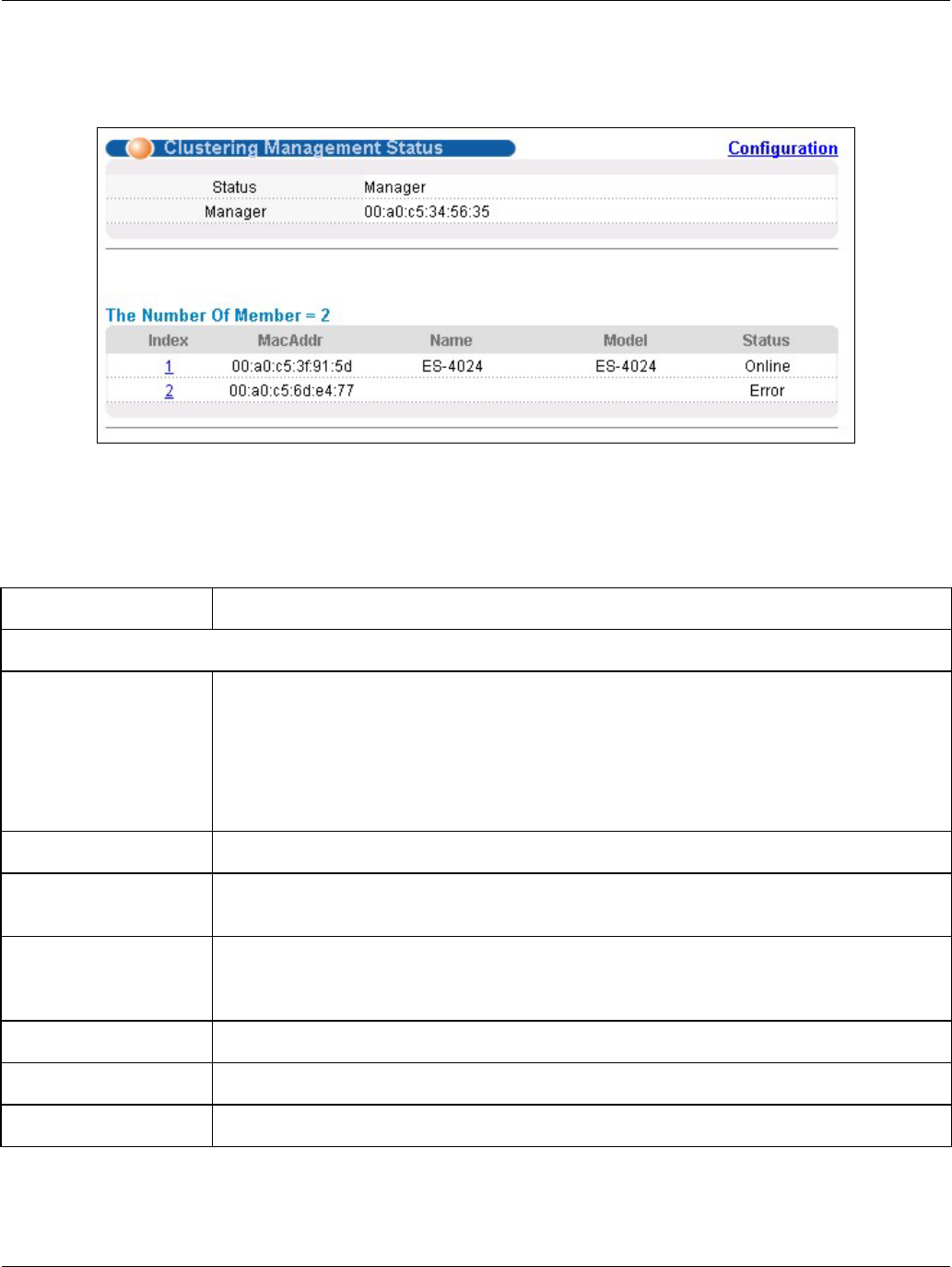
25.2 Cluster Management Status
Click Management in the navigation panel and then Cluster Management to display the following screen.
Figure 25-2 Cluster Management Status
The following table describes the labels in this screen.
Table 25-2 Cluster Management Status
LABEL DESCRIPTION
A cluster can only have one manager.
Status This field displays the role of this switch within the cluster.
o Manager
o Member (you see this if you access this screen in the cluster member switch directly
and not via the cluster manager)
o None (neither a manager nor a member of a cluster)
Manager This field displays the cluster manager switch’s hardware MAC Address.
The Number of Member This field displays the number of switches that make up this cluster. The following fields
describe the cluster member switches.
Index You can manage cluster member switches via the cluster manager switch. Each number
in the Index column is a hyperlink leading to the cluster member switch’s web
configurator (see Figure 25-3).
MacAddr This is the cluster member switch’s hardware MAC Address.
Name This is the cluster member switch’s System Name.
Model This field displays the model name.