
User`s guide


Dimension GS-3012 Gigabit Ethernet Switch
Hardware Installation 2-1
Chapter 2
Hardware
Installation
This chapter shows two switch installation scenarios.
2.1 Installation Scenarios
The switch can be placed on a desktop or rack-mounted on a standard EIA rack. Use the rubber feet in a desktop
installation and the brackets in a rack-mounted installation.
For proper ventilation, allow at least 4 inches (10 cm) of clearance at the front and 3.4 inches (8
cm) at the back of the switch. This is especially important for enclosed rack installations.
2.1.1 Desktop Installation Procedure
Step 1. Make sure the switch is clean and dry.
Step 2. Set the switch on a smooth, level surface strong enough to support the weight of the switch and the
connected cables. Make sure there is a power outlet nearby.
Step 3. Make sure there is enough clearance around the switch to allow air circulation and the attachment of cables
and the power cord.
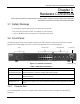
Step 4. Remove the adhesive backing from the rubber feet.
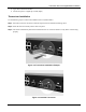
Step 5. Attach the rubber feet to each corner on the bottom of the switch. These rubber feet help protect the switch
from shock or vibration and ensure space between switches when stacking.
Figure 2-1 Attaching Rubber Feet
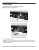
Do not block the ventilation holes. Leave space between switches when stacking.
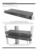
2.1.2 Rack-Mounted Installation
The switch can be mounted on an EIA standard size, 19-inch rack or in a wiring closet with other equipment.
Follow the steps below to mount your switch on a standard EIA rack using a rack-mounting kit.