
User`s guide


Chapter 3 Hardware Overview
GS3700/XGS3700 Series User’s Guide
35
• VT100 terminal emulation
• 9600 bps
• No parity, 8 data bits, 1 stop bit
• No flow control
Connect the male 9-pin end of the RS-232 console cable to the console port of the Switch. Connect
the female end to a serial port (COM1, COM2 or other COM port) of your computer.
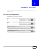
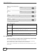
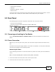
3.2 Rear Panel
The following figures show the rear panels of the Switch. The rear panels contain:
• A slot for a fan module (A)
• Two slots for power modules with power receptacles (B and C)
Figure 12 Rear Panel
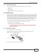
3.2.1 Removing and Installing the Fan Module
See the Fan Module Hardware Installation Guide to see how to install the fan module in the
Switch.
3.2.2 Power Connection
Make sure you are using the correct power source and that no objects obstruct the airflow of the
fans.
The Switch uses two power supply modules, one of which is redundant, so if one power module fails
the system can operate on the remaining module.
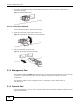
Connecting the Power
Use the following procedures to connect the Switch to a power source after you have installed it in
a rack.
Note: Use the included power cord for the AC power connection.
1 Connect the female end of the power cord to the AC power socket.
2 Connect the other end of the cord to a power outlet.
C
A
B