IES-612-51A 12-port ADSL2/2+ Standalone mini-DSLAM User’s Guide Version 3.52 9/2007 Edition 1 DEFAULT LOGIN IP Address http://192.168.1.1 User Name admin Password 1234 www.zyxel.
About This User's Guide About This User's Guide Intended Audience This manual is intended for people who want to configure the IES-612-51A using the web configurator. You should have at least a basic knowledge of TCP/IP networking concepts and topology. Related Documentation • Quick Start Guide The Quick Start Guide is designed to help you get up and running right away. It contains information on setting up your network and configuring for Internet access.
Document Conventions Document Conventions Warnings and Notes These are how warnings and notes are shown in this User’s Guide. 1 " Warnings tell you about things that could harm you or your IES-612-51A. Notes tell you other important information (for example, other things you may need to configure or helpful tips) or recommendations. Syntax Conventions • The IES-612-51A may be also referred to as the “device”, the “system” or the “product” in this User’s Guide.
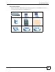
Document Conventions Icons Used in Figures Figures in this User’s Guide may use the following generic icons. The IES-612-51A icon is not an exact representation of your IES-612-51A.
Safety Warnings Safety Warnings 1 For your safety, be sure to read and follow all warning notices and instructions. • Do NOT use this product near water, for example, in a wet basement or near a swimming pool. • Do NOT expose your device to dampness, dust or corrosive liquids. • Do NOT store things on the device. • Do NOT install, use, or service this device during a thunderstorm. There is a remote risk of electric shock from lightning. • Connect ONLY suitable accessories to the device.
Safety Warnings IES-612-51A User’s Guide 7
Safety Warnings 8 IES-612-51A User’s Guide
Contents Overview Contents Overview Introduction ............................................................................................................................ 39 Getting to Know the IES-612-51A ............................................................................................. 41 Hardware Installation ................................................................................................................. 45 Front Panel ......................................................
Contents Overview Syslog ...................................................................................................................................... 223 Access Control ........................................................................................................................ 225 Routing Protocol, Alarm and Management ....................................................................... 233 Static Routing ............................................................................
Table of Contents Table of Contents About This User's Guide .......................................................................................................... 3 Document Conventions............................................................................................................ 4 Safety Warnings........................................................................................................................ 6 Contents Overview .......................................................
Table of Contents 3.2.3 Notes About MDFs (Main Distribution Frames) ......................................................... 51 3.2.4 Telco-50 Cables ......................................................................................................... 51 3.2.5 Telco-50 Connections ................................................................................................. 52 3.2.6 ADSL Connections ....................................................................................................
Table of Contents Chapter 10 Switch Setup ........................................................................................................................... 97 10.1 GARP Timer Setup ............................................................................................................ 97 10.2 Switch Modes .................................................................................................................... 97 10.2.1 Standalone Switch Mode ........................................
Table of Contents 14.4 Upstream Policing ........................................................................................................... 130 14.5 VC Profile Screen ............................................................................................................ 131 14.6 Alarm Profile Screen ........................................................................................................ 133 14.7 IGMP Filtering ...................................................................
Table of Contents 18.2 Static Multicast Screen .................................................................................................... 163 Chapter 19 Multicast VLAN...................................................................................................................... 165 19.1 Multicast VLAN Overview ................................................................................................ 165 19.2 MVLAN Status Screen .......................................................
Table of Contents Chapter 26 DHCP Snoop.......................................................................................................................... 191 26.1 DHCP Snoop Overview ................................................................................................... 191 26.2 DHCP Snoop Screen ....................................................................................................... 191 26.3 DHCP Snoop Status Screen .......................................................
Table of Contents Chapter 32 Downstream Broadcast........................................................................................................ 221 32.1 Downstream Broadcast ................................................................................................... 221 32.2 Downstream Broadcast Screen ....................................................................................... 221 Chapter 33 Syslog ...............................................................................
Table of Contents 38.1 Introduction to MAC Table ............................................................................................... 245 38.2 MAC Table Screen ........................................................................................................... 246 Chapter 39 ARP Table .............................................................................................................................. 247 39.1 Introduction to ARP Table ............................................
Table of Contents 42.6 Statistics Port Command ................................................................................................. 281 Chapter 43 Alarm Commands ................................................................................................................. 283 43.1 Alarm Commands ............................................................................................................ 283 43.2 General Alarm Command Parameters ..............................................
Table of Contents Chapter 45 IEEE 802.1Q Tagged VLAN Commands .............................................................................. 299 45.1 Introduction to VLANs ...................................................................................................... 299 45.2 IEEE 802.1Q Tagging Types ........................................................................................... 299 45.3 Filtering Databases ................................................................................
Table of Contents 47.3 IGMP Filter Commands ................................................................................................... 314 47.3.1 IGMP Filter Show Command ................................................................................. 314 47.3.2 IGMP Filter Set Command ..................................................................................... 314 47.3.3 IGMP Filter Profile Set Command .......................................................................... 315 47.3.
Table of Contents 49.1 IP Commands Introduction .............................................................................................. 331 49.2 IP Settings and Default Gateway ..................................................................................... 331 49.3 General IP Commands .................................................................................................... 332 49.3.1 Show ...............................................................................................
Table of Contents 52.1.9 DSL Port Tel Command ......................................................................................... 348 52.1.10 DSL Port Loopback Command ............................................................................ 349 52.1.11 DSL Port Upstream PSD Command .................................................................... 349 52.1.12 DSL Port Downstream PSD Command ............................................................... 350 52.1.
Table of Contents 53.3.1 PVC Show Command ............................................................................................ 377 53.3.2 PVC Set Command ................................................................................................ 378 53.3.3 PVC Delete Command ........................................................................................... 379 53.4 Priority-based PVCs .....................................................................................................
Table of Contents 54.2 ACL Assignment Commands .......................................................................................... 402 54.2.1 ACL Assignment Set Command ............................................................................ 402 54.2.2 ACL Assignment Delete Command ....................................................................... 402 54.2.3 ACL Assignment Show Command .........................................................................
Table of Contents Appendix B Customer Support............................................................................................. 433 Index.......................................................................................................................................
List of Figures List of Figures Figure 1 MTU Application ...................................................................................................................... 42 Figure 2 Curbside Application ............................................................................................................... 42 Figure 3 Attaching Rubber Feet .............................................................................................................
List of Figures Figure 39 User Account .......................................................................................................................... 93 Figure 40 Authentication ......................................................................................................................... 94 Figure 41 Port Isolation with Standalone Switch Mode Example ........................................................... 98 Figure 42 Port Isolation with Daisychain Switch Mode Example ...........
List of Figures Figure 82 STP Root Ports and Designated Ports ................................................................................. 176 Figure 83 Spanning Tree Protocol Status ............................................................................................. 177 Figure 84 Spanning Tree Protocol ........................................................................................................ 179 Figure 85 RADIUS Server ...........................................................
List of Figures Figure 125 Diagnostic ........................................................................................................................... 241 Figure 126 MAC Table Filtering Flowchart ........................................................................................... 245 Figure 127 MAC Table .......................................................................................................................... 246 Figure 128 ARP Table .......................................
List of Figures Figure 168 MAC Count Enable Command Example ............................................................................ 310 Figure 169 MAC Count Disable Command Example ............................................................................311 Figure 170 MAC Count Set Command Example ...................................................................................311 Figure 171 IGMP Snoop Show Command Example ..........................................................................
List of Figures Figure 211 Example: Enter the Management Password ...................................................................... 339 Figure 212 Example: Transfer the Firmware File ................................................................................. 339 Figure 213 Example: Close FTP Client ................................................................................................ 339 Figure 214 DSL Port Show Command Example ..........................................................
List of Figures Figure 254 Alarm Profile Set Command Example ................................................................................ 372 Figure 255 Alarm Profile Delete Command Example ........................................................................... 372 Figure 256 Alarm Profile Map Command Example .............................................................................. 373 Figure 257 Alarm Profile Showmap Command Example ............................................................
List of Figures Figure 297 Example Xmodem Upload .................................................................................................. 415 Figure 298 Telco-50 Pin Assignments .................................................................................................. 425 Figure 299 Console Cable RJ-11 Male Connector ............................................................................... 426 Figure 300 Console Cable DB-9 Female Connector ...........................................
List of Tables List of Tables Table 1 Front Panel Ports ...................................................................................................................... 49 Table 2 LEDs ......................................................................................................................................... 49 Table 3 Navigation Panel Submenu Links ............................................................................................. 63 Table 4 Web Configurator Screens ..........
List of Tables Table 39 IGMP Count .......................................................................................................................... 159 Table 40 IGMP Port Info ...................................................................................................................... 160 Table 41 IGMP Port Group .................................................................................................................. 161 Table 42 Static Multicast ................................
List of Tables Table 82 ARP Table ............................................................................................................................. 248 Table 83 Alarm Status .......................................................................................................................... 249 Table 84 Alarm Descriptions ................................................................................................................ 250 Table 85 Alarm Event Setup ..........................
List of Tables 38 IES-612-51A User’s Guide
P ART I Introduction Getting to Know the IES-612-51A (41) Hardware Installation (45) Front Panel (49) 39
CHAPTER 1 Getting to Know the IES-612-51A This chapter introduces the main features and applications of your IES-612-51A. It also introduces the ways you can manage the IES-612-51A. 1.1 Overview The IES-612-51A (Standalone mini-DSLAM) is an IP-based DSLAM. The IES-612-51A aggregates traffic from 12 ADSL lines to two Ethernet ports to connect ADSL subscribers to the Internet. You can use the built-in web configurator to manage and configure the IES-612-51A.
Chapter 1 Getting to Know the IES-612-51A Figure 1 MTU Application 1.2.2 Curbside Application The IES-612-51A can be used by an Internet Service Provider (ISP) in a street cabinet to form a "mini POP (Point-of-Presence)" to provide broadband services to residential areas that are too far away from the ISP to avail of DSL services. Residents need a DSL modem, connected as shown in the previous figure.
Chapter 1 Getting to Know the IES-612-51A 1.3 Ways to Manage the IES-612-51A Use any of the following methods to manage the IES-612-51A. • Web Configurator. This is recommended for everyday management of the IES-612-51A using a (supported) web browser. See Chapter 4 on page 61. • Command Line Interface. Line commands offer an alternative to the Web Configurator and may be necessary to configure advanced features. See Chapter 41 on page 257. • FTP.
Chapter 1 Getting to Know the IES-612-51A 44 IES-612-51A User’s Guide
CHAPTER 2 Hardware Installation This chapter explains how to install the IES-612-51A. 2.1 General Installation Instructions Before you begin, read all the safety warnings in Safety Warnings on page 6, and make sure you follow them. Perform the installation as follows: 1 2 3 4 Make sure the IES-612-51A power is not connected. Install the hardware. See Section 2.1 on page 45. See Section 3.1 on page 49 for instructions on making front panel connections. See Section 3.2.
Chapter 2 Hardware Installation EX AM PL E Figure 3 Attaching Rubber Feet " Do not block the ventilation holes. Leave space between IES-612-51A when stacking. 2.2.2 Rack-Mounted Installation 2.2.2.1 Rack-mounted Installation Requirements The IES-612-51A can be mounted on an EIA standard size, 19-inch rack or in a wiring closet with other equipment. Follow the steps below to mount your IES-612-51A on a standard EIA rack using a rack-mounting kit.
Chapter 2 Hardware Installation " Do not block the ventilation holes. Leave space between devices when stacking. 2.2.2.2 Rack-Mounted Installation Procedure Do the following to rack-mount the IES-612-51A. The figures in this section are examples and are not intended as an exact representation of the IES-612-51A. 1 Align one bracket with the holes on one side of the IES-612-51A and secure it with the bracket screws smaller than the rack-mounting screws. 2 Attach the other bracket in a similar fashion.
Chapter 2 Hardware Installation 48 IES-612-51A User’s Guide
CHAPTER 3 Front Panel This chapter describes the front panel and rear panel of the IES-612-51A and shows you how to make the hardware connections. 3.1 Front Panel The figure below shows the front panel of the IES-612-51A. Figure 6 Front Panel: AC Input 3.1.1 Front Panel Ports The following table describes the port labels on the front panel.
Chapter 3 Front Panel Table 2 LEDs (continued) LED COLOR STATUS DESCRIPTION SYS Green On The IES-612-51A’s system is running. Blinking The IES-612-51A is booting. Off The IES-612-51A’s stem is not running. On The IES-612-51A has a successful 10 Mbps connection on this port. Blinking The IES-612-51A is sending/receiving data on this port. On The IES-612-51A has a successful 100 Mbps connection on this port. Blinking The IES-612-51A is sending/receiving data on this port.
Chapter 3 Front Panel 3.2.2 LAN Port (Ethernet) Connection Connect the LAN port of your IES-612-51A to an Ethernet WAN switch using a straightthrough Category 5 UTP (Unshielded Twisted Pair) cable with RJ-45 connectors. You may connect multiple IES-612-51A units to the same Ethernet switch (up to the number of ports available on the Ethernet switch). 3.2.
Chapter 3 Front Panel Figure 8 Telco-50 Cable with RJ-11 Connectors 3.2.5 Telco-50 Connections The internal DSL splitters separate the voice signals from the DSL signals. They feed the DSL signals to the IES-612-51A and divert the voice signals to the CO lines of the Telco-50 connector. Connect the CO lines of the Telco-50 connector to the PBX or PSTN/ISDN switch. Connect the USER lines of the Telco-50 connector to the subscribers' telephone wiring.
Chapter 3 Front Panel Figure 9 Installation Overview " You can also attach RJ-11 connectors to the Telco-50 cable and connect directly to a DSL modem(s) or patch panel. This chapter discusses connections using MDFs. 3.2.7 Typical MDF Scenarios This section describes typical installation scenarios. 3.2.7.1 Installation Scenario A You want to install the IES-612-51A in an environment where there are no previously installed MDFs.
Chapter 3 Front Panel Figure 10 Installation Scenario A 3.2.7.1.1 Procedure To Connect To An MDF 1 Connect the Telco-50 connector end of the cable to the Telco-50 connector. 2 Connect the USER wiring on the other end of the Telco-50 cable to the upper ports of the MDF using a punch-down tool. 3 Connect the telephone wiring from each end-user's DSL modem to the lower ports of the MDF. 3.2.7.2 Installation Scenario B Phone service is available.
Chapter 3 Front Panel Figure 11 One MDF for End-user and CO Connections This installation scenario requires three MDFs. Please refer to the following figure for the connection schema. • MDF 1 is the original MDF used for telephone connections only. • MDF 2 is used for telephone connections only. • MDF 3 is for ADSL service connections. " Change the wiring (in the following figure) from MDF 1 to MDF 3 for telephone subscribers who want ADSL service.
Chapter 3 Front Panel Figure 12 Installation Scenario B 3.2.7.2.1 Procedure To Connect To MDFs 1 Connect the Telco-50 connector end of the cable to the Telco-50 connector. 2 Connect the USER wiring on the other end of the Telco-50 cable to the upper ports of MDF 3 using a punch-down tool. 3 Connect the telephone wiring from the end-user's DSL modem(s) to the lower ports of MDF 3. 4 Connect the CO wiring of the Telco-50 cable to the lower ports of MDF 2 using a punchdown tool.
Chapter 3 Front Panel " Users A and B have telephone (only) service. Figure 13 Two Separate MDFs for End-user and CO Connections This installation scenario requires four MDFs. Please refer to the following figure for the DSL connection schema. • MDFs 1 and 2 are the two original MDFs. • MDFs 3 and 4 are two additional MDFs you need. " User A still has telephone service only. User B now has telephone and DSL service (see the following figure).
Chapter 3 Front Panel Figure 14 Installation Scenario C 3.2.7.3.1 Procedure To Connect To MDFs 1 Connect the Telco-50 connector end of the cable to the Telco-50 connector. 2 Connect the USER wiring on the other end of the Telco-50 cable to the upper ports of MDF 3 using a punch-down tool. 3 Connect the lower ports of MDF 3 to the upper ports of MDF 2 for those users that want DSL service.
P ART II Basic Settings Introducing the Web Configurator (61) Initial Configuration (69) Home and Port Statistics Screens (75) System Information (87) General Setup (91) User Account (93) Switch Setup (97) IP Setup (103) ENET Port Setup (105) xDSL Port Setup (107) xDSL Profiles Setup (125) xDSL Line Data (137) 59
CHAPTER 4 Introducing the Web Configurator This chapter tells how to access and navigate the web configurator. 4.1 Web Configurator Overview The web configurator allows you to use a web browser to manage the IES-612-51A. 4.2 Screen Privilege Levels There is a high or low privilege level for each screen. High privilege screens are only available to administrators with high privilege access.
Chapter 4 Introducing the Web Configurator Figure 15 Login 2 Type admin in the User Name field and your password (default: 1234) in the Password field. Click OK. The main screen appears. This is the web configurator’s main screen. Figure 16 Home B C A A - Click the menu items to open submenu links, and then click on a submenu link to open the screen in the main window. See Section 4.4 on page 63 for more information. B - Click this to open the Home screen.
Chapter 4 Introducing the Web Configurator 4.4 Navigation Panel In the navigation panel, click a menu item to reveal a list of submenu links. Click a submenu link to go to the corresponding screen. Table 3 Navigation Panel Submenu Links BASIC SETTING ADVANCED APPLICATION ROUTING PROTOCOL ALARM MANAGEMENT CONFIG SAVE The following table briefly describes the functions of the screens that you open by clicking the navigation panel’s sub-links.
Chapter 4 Introducing the Web Configurator Table 4 Web Configurator Screens (continued) LABEL DESCRIPTION IP Setup Use this screen to configure the system and management IP addresses and subnet masks. ENET Port Setup Use this screen to configure settings for the Ethernet ports. xDSL Port Setup Use these screens for configuring settings for individual DSL ports. xDSL Profiles Setup Use these screens for configuring profiles for the DSL ports.
Chapter 4 Introducing the Web Configurator Table 4 Web Configurator Screens (continued) LABEL DESCRIPTION Alarm Status Use these screens to view the alarms that are currently in the system. Alarm Event Setup Use these screens to view and set the severity levels of the alarms and where the system is to send them. Alarm Port Setup Use this screen to set the alarm severity threshold for recording alarms on an individual port(s).
Chapter 4 Introducing the Web Configurator Figure 18 User Account Enter the new password in the Password and Retype Password to confirm fields, and click Modify. Do not forget to click Config Save before you exit the web configurator. See Section 4.6 on page 66. 4.6 Saving Your Configuration Click Apply in a configuration screen when you are done modifying the settings in that screen to save your changes back to the run-time memory.
Chapter 4 Introducing the Web Configurator Figure 19 Logout IES-612-51A User’s Guide 67
Chapter 4 Introducing the Web Configurator 68 IES-612-51A User’s Guide
CHAPTER 5 Initial Configuration This chapter describes initial configuration for the IES-612-51A. See Chapter 56 on page 417 for various default settings of the IES-612-51A. 5.1 Initial Configuration Overview This chapter shows what you first need to do to provide service to DSL subscribers. 5.2 Initial Configuration This chapter uses the web configurator for initial configuration. See the CLI chapters for information on the commands. Use Internet Explorer 6 and later versions with JavaScript enabled.
Chapter 5 Initial Configuration " If you change the IP address of the IES-612-51A, after you click Apply IP setting, you have to use the new IP address to log into the web configurator again. 4 If your subscribers use VPI 0 and VCI 33 (the default for all of the DSL ports), go to step 13. Otherwise, use the following steps to change the VPI and VCI settings for all of the DSL ports. First, you will delete the default virtual channel from all of the DSL ports. (You cannot edit it).
Chapter 5 Initial Configuration Figure 22 VC Setup 7 Select any virtual channel’s Select radio button, and click Delete. The following screen appears. Figure 23 VC Setup, Delete 8 Click OK. The following screen appears.
Chapter 5 Initial Configuration 9 Click All, and then click Apply. The VC Setup screen is updated. Figure 25 VC Setup 10 Select Super Channel to allow the channel to forward frames belonging to multiple VLAN groups (that are not assigned to other channels). Then, enter the VPI and VCI that you use. Leave the other default settings, and click Add. The VC Setup screen is updated. Figure 26 VC Setup 11 Select the new channel’s Select radio button. Click Copy, and then click Paste.
Chapter 5 Initial Configuration Figure 27 Select Ports 12 Click All, and then click Apply. The VC Setup screen is updated. Figure 28 VC Setup 13 Click Config Save, Config Save. The Config Save screen appears. Figure 29 Config Save 14 Click Save. The following screen should appear.
Chapter 5 Initial Configuration Figure 30 Config Save, Save Successful You can now use the device (with the other settings set to the defaults) to provide service to DSL subscribers. See Section 56.4 on page 423 for information on other default settings.
CHAPTER 6 Home and Port Statistics Screens This chapter describes the Home (status), Port Statistics, and RMON screens. 6.1 Home Screen The Home screen of the web configurator displays a port statistical summary with links to each port showing statistical details. To open this screen, click Home in any web configurator screen. Figure 31 Home The following table describes the labels in this screen.
Chapter 6 Home and Port Statistics Screens Table 5 Home (continued) LABEL DESCRIPTION Media This field displays the type of media that this Ethernet port is using for a connection. “-“ displays when the port is disabled or not connected. Duplex This field displays whether the port is using half or full-duplex communication. ““ displays when the port is disabled or not connected. Up Time This field shows the total amount of time in hours, minutes and seconds the port’s connection has been up.
Chapter 6 Home and Port Statistics Screens Figure 32 Port Statistics (Ethernet) The following table describes the labels in this screen. Table 6 Port Statistics (Ethernet) LABEL DESCRIPTION RMON Click this to open the RMON Statistics screen. Return Click this to go back to the Home screen. Port Use this drop-down list box to select a port for which you wish to view statistics. This field identifies the port described in this screen.
Chapter 6 Home and Port Statistics Screens Table 6 Port Statistics (Ethernet) (continued) 78 LABEL DESCRIPTION Rx mac pause This field shows the number of valid IEEE 802.3x Pause frames received on this port. Rx fragments This field shows the number of frames received that were less than 64 octets long, and contained an invalid FCS, including non-integral and integral lengths. Rx error overrun This field shows how many times an Ethernet transmitter overrun occurred.
Chapter 6 Home and Port Statistics Screens Table 6 Port Statistics (Ethernet) (continued) LABEL DESCRIPTION packet(128-255) This field shows the number of frames received and transmitted (including bad frames) that were 128 to 255 octets in length (this includes FCS octets but excludes framing bits). packet(256-511) This field shows the number of frames received and transmitted (including bad frames) that were 256 to 511 octets in length (this includes FCS octets but excludes framing bits).
Chapter 6 Home and Port Statistics Screens Figure 33 Port Statistics (DSL) The following table describes the labels in this screen. Table 7 Port Statistics (DSL) 80 LABEL DESCRIPTION RMON Click this to open the RMON Statistics screen. Return Click this to go back to the Home screen. xDSL Port Use this drop-down list box to select a port for which you wish to view statistics. This field identifies the port described in this screen.
Chapter 6 Home and Port Statistics Screens Table 7 Port Statistics (DSL) (continued) LABEL DESCRIPTION Rx discard packets This field shows the number of received packets that were dropped on this port. Some of the possible reasons for the discarding of received (rx) packets are: • The packet filter is enabled and the packets matched a packet filter. • The MAC filter is enabled and the IES-612-51A dropped the packets according to the MAC filter’s configuration.
Chapter 6 Home and Port Statistics Screens Figure 34 Port Statistics (RMON) The following table describes the labels in this screen. Table 8 Port Statistics (RMON) 82 LABEL DESCRIPTION Port Statistics Click this to go back to the previous screen. Enet1 Click this to look at the RMON history for this port. Enet2 Click this to look at the RMON history for this port. EtherStatsDropEvents This field displays the total number of packets that were dropped on this port.
Chapter 6 Home and Port Statistics Screens Table 8 Port Statistics (RMON) (continued) LABEL DESCRIPTION EtherStatsOversizePkts This field displays the total number of packets that were too big received/transmitted on this port. EtherStatsFragments This is the number of frames received/transmitted that were less than 64 octets long, and contained an invalid FCS, including non-integral and integral lengths.
Chapter 6 Home and Port Statistics Screens Figure 35 Port Statistics (RMON History)) The following table describes the labels in this screen. Table 9 Port Statistics (RMON History) LABEL DESCRIPTION Index:Interval Select the index of the sample interval and the desired data sampling time (in seconds). Apply Click this to use the selected data sampling time. Refresh Click this to update this screen. Sample Index This field display the sample number.
Chapter 6 Home and Port Statistics Screens Figure 36 Port Statistics (RMON History Detail)) The following table describes the labels in this screen. Table 10 Port Statistics (RMON History Detail) LABEL DESCRIPTION UP Click this to return to the previous screen. Refresh Click this to update this screen. Index This field displays the index of the sample interval. Sample Index This field displays the sample number. Interval Start This field displays the data sampling time.
Chapter 6 Home and Port Statistics Screens Table 10 Port Statistics (RMON History Detail) (continued) 86 LABEL DESCRIPTION Jabbers This is the number of frames received/transmitted that were longer than 1518 octets (non VLAN) or 1522 octets (VLAN) and contained an invalid FCS, including alignment errors. Collisions This is the number of frames for which transmission failed due to excessive collisions.
CHAPTER 7 System Information The System Information screen displays general device information (such as firmware version number) and hardware polling information (such as temperature status). You can check the firmware version number and monitor the hardware status in this screen. To open this screen, click Basic Setting, System Information.
Chapter 7 System Information The following table describes the labels in this screen. Table 11 System Info LABEL DESCRIPTION System Name This field displays the device's model name. ZyNOS F/W Version This field displays the version number of the device’s current firmware including the date created. DSP Code Version This field displays the Digital Signal Processor firmware version number. This is the modem code firmware. Hardware Version This is the version of the physical device hardware.
Chapter 7 System Information Table 11 System Info (continued) LABEL DESCRIPTION Volt. (Hi) Use these fields to configure the highest voltage limit at each sensor. Volt. (Lo) Use these fields to configure the lowest voltage limit at each sensor. Poll Interval(s) Set Interval The text box displays how often (in seconds) this screen refreshes. You may change the refresh interval by typing a new number in the text box and then clicking Set Interval. Stop Click Stop to halt statistic polling.
Chapter 7 System Information 90 IES-612-51A User’s Guide
CHAPTER 8 General Setup The General Setup screen allows you to configure general device identification information. It also allows you to set the system time manually or get the current time and date from an external server when you turn on your device. The real time is then displayed in the logs. To open this screen, click Basic Setting, General Setup. Figure 38 General Setup The following table describes the labels in this screen.
Chapter 8 General Setup Table 12 General Setup (continued) 92 LABEL DESCRIPTION Model This field displays your device type. Use Time Server When Bootup Select the time service protocol that the timeserver uses. Not all time servers support all protocols, so you may have to use trial and error to find a protocol that works. The main differences between them are the time format.
CHAPTER 9 User Account The User Account screens allows you to set up and configure system administrator accounts for the IES-612-51A. You can also configure the authentication policy for IES-612-51A administrators. This is different than port authentication in Chapter 23 on page 181. See Chapter 23 on page 181 for background information on authentication. 9.1 User Account Screen To open this screen, click Basic Setting, User Account.
Chapter 9 User Account Table 13 User Account (continued) LABEL DESCRIPTION Privilege Select a privilege level to determine which screens the administrator can use. There is a high, medium or low privilege level for each command. Select high to allow the administrator to use all commands including the lower privilege commands. High privilege commands include things like creating administrator accounts, restarting the system and resetting the factory defaults.
Chapter 9 User Account The following table describes the labels in this screen. Table 14 User Account LABEL DESCRIPTION User account Click this to open the User Account screen. See Section 9.1 on page 93. Authentication Mode Select the process by which the IES-612-51A authenticates administrators. local - Search the local database. You maintain this database in the User Account screen. radius - Check an external RADIUS database using the settings below.
Chapter 9 User Account 96 IES-612-51A User’s Guide
CHAPTER 10 Switch Setup The Switch Setup screen allows you to set up and configure global device features. 10.1 GARP Timer Setup GARP (Generic Attribute Registration Protocol) allows network devices to register and deregister attribute values with other GARP participants within a bridged LAN. GARP is a protocol that provides a generic mechanism for protocols that serve a more specific application, for example, GVRP (GARP VLAN Registration Protocol).
Chapter 10 Switch Setup 10.2.2 Port Isolation with Standalone Switch Mode Example The following graphic shows IES-612-51A 1 and 2 connected to each other and the Ethernet backbone switch (3) in a network topology that creates a loop. The IES-612-51A are using the standalone switch mode and have RSTP enabled. In this example, both IES-612-51A have port isolation turned on. Communications between A and B must first go through another switch (3 in the figure).
Chapter 10 Switch Setup With port isolation turned on, communications between A and B must first go through another switch or router (3 in the figure). A and B also cannot communicate with C without their communications going through another switch or router. Figure 42 Port Isolation with Daisychain Switch Mode Example 10.3 Switch Setup Screen To open this screen, click Basic Setting, Switch Setup.
Chapter 10 Switch Setup Figure 43 Switch Setup The following table describes the labels in this screen. Table 15 Switch Setup LABEL DESCRIPTION MAC Address Learning Aging Time Enter a time from 10 to 10,000 seconds. This is how long all dynamically learned MAC addresses remain in the MAC address table before they age out (and must be relearned). Enter 0 to disable the aging out of MAC addresses. GARP Timer: Switches join VLANs by making a declaration.
Chapter 10 Switch Setup Table 15 Switch Setup (continued) LABEL DESCRIPTION MAC Anti-Spoofing Select this if you want the IES-612-51A to generate an alarm and issue a SNMP trap when an existing MAC address appears on another port. Switch Mode Select Standalone to use both of the IES-612-51A’s Ethernet ports (ENET 1 and ENET 2) as uplink ports. Note: Standalone mode is recommended for network topologies that use loops. Use Daisychain mode to cascade (daisychain) multiple IES-612-51A.
Chapter 10 Switch Setup 102 IES-612-51A User’s Guide
CHAPTER 11 IP Setup The IP Setup screen allows you to configure a device IP address, subnet mask and DNS (domain name server) for management purposes. To open this screen, click Basic Setting, IP Setup. Figure 44 IP Setup The following table describes the labels in this screen. Table 16 IP Setup LABEL DESCRIPTION IP Enter the IP address of your IES-612-51A in dotted decimal notation for example 1.2.3.4. IP Mask Enter the IP subnet mask of your IES-612-51A in dotted decimal notation for example 255.
Chapter 11 IP Setup 104 IES-612-51A User’s Guide
CHAPTER 12 ENET Port Setup The ENET Port Setup screen allows you to configure settings for the Ethernet ports. To open this screen, click Basic Setting, ENET Port Setup. Figure 45 ENET Port Setup The following table describes the labels in this screen. Table 17 ENET Port Setup LABEL DESCRIPTION Port This is the port index number. Active Select the check box to turn on the port. Clear it to disable the port. Name Enter a descriptive name that identifies this port.
Chapter 12 ENET Port Setup 106 IES-612-51A User’s Guide
CHAPTER 13 xDSL Port Setup This chapter explains how to configure settings for profiles and individual ADSL ports. It also covers how to configure virtual channels and virtual channel profiles. 13.1 ADSL Standards Overview These are the ADSL standards and rates that the IES-612-51A supports at the time of writing. The actual transfer rates will vary depending on what the subscriber’s device supports, the line conditions and the connection distance.
Chapter 13 xDSL Port Setup For example, you could set up different profiles for different kinds of accounts (for example, economy, standard and premium). Assign the appropriate profile to an ADSL port and it takes care of a large part of the port’s configuration maximum and minimum transfer rates. You still get to individually enable or disable each port, as well as configure its channels and operational mode. 13.
Chapter 13 xDSL Port Setup 13.6 Default Settings The default profile always exists and all of the ADSL ports use the default profile settings when the IES-612-51A is shipped. The default profile's name is set to DEFVAL. See Chapter 56 on page 417 for the settings of the default profile and ADSL port default settings. 13.7 xDSL Port Setup Screen To open this screen, click Basic Setting, xDSL Port Setup. Figure 46 xDSL Port Setup The following table describes the labels in this screen.
Chapter 13 xDSL Port Setup Table 19 xDSL Port Setup (continued) LABEL DESCRIPTION Copy Port Paste Do the following to copy settings from one DSL port to another DSL port or ports. 1. Select the number of the DSL port from which you want to copy settings. 2. Select the settings that you want to copy. 3. Click Paste and the following screen appears. 4. Select to which ports you want to copy the settings. Use All to select every port. Use None to clear all of the check boxes. 5.
Chapter 13 xDSL Port Setup Table 19 xDSL Port Setup (continued) LABEL DESCRIPTION Port This field shows each ADSL port number. Active This field shows the active status of this port. The port may be enabled or disabled. This is configured in the xDSL Port Setting screen (see Section 13.7.1 on page 111). Customer Info This field shows the customer information provided for this port. This is configured in the xDSL Port Setting screen (see Section 13.7.1 on page 111).
Chapter 13 xDSL Port Setup Figure 48 xDSL Port Setting The following table describes the labels in this screen. Table 20 xDSL Port Setting LABEL DESCRIPTION Last Page Click this to return to the previous screen. General Setup 112 Active Select this check box to turn on this ADSL port. Customer Info Enter information to identify the subscriber connected to this ADSL port. You can use up to 31 printable ASCII characters (including spaces and hyphens).
Chapter 13 xDSL Port Setup Table 20 xDSL Port Setting (continued) LABEL DESCRIPTION Alarm Profile Select the port’s alarm profile. The alarm profile defines alarm thresholds for the ADSL port. The IES-612-51A sends an alarm trap and generates a syslog entry when the thresholds of the alarm profile are exceeded (see Section 14.6 on page 133). IGMP Filter Profile The IGMP filter profile defines which multicast groups a port can join. Select a profile of IGMP filter settings to assign to this port.
Chapter 13 xDSL Port Setup Table 20 xDSL Port Setting (continued) LABEL DESCRIPTION L2 Time Set minimum time (in seconds) that the ADSL line must stay in the L2 power mode before reducing the power again in the L2 power mode. L2 ATPR Set the maximum Aggregate Transmit Power Reduction (ATPR) in decibels (dB) that is permitted in a L2 power reduction. The system can gradually decrease the ADSL line transmission power while it is in the L2 power mode.
Chapter 13 xDSL Port Setup Table 20 xDSL Port Setting (continued) LABEL DESCRIPTION DS Carrier1 (256~511) Mask0 represents tones 256~287 Mask1 represents tones 288~319 Mask2 represents tones 320~351 Mask3 represents tones 352~383 Mask4 represents tones 384~415 Mask5 represents tones 416~447 Mask6 represents tones 448~479 Mask7 represents tones 480~511 For example, use 0x00001000 in Mask1 to disable downstream carrier tone 307. Use 0x0000f000 in Mask1 to disable downstream carrier tones 304 to 307.
Chapter 13 xDSL Port Setup 13.8.2 LLC LLC is a type of encapsulation where one VC (Virtual Circuit) carries multiple protocols with each packet header containing protocol identifying information. Despite the extra bandwidth and processing overhead, this method may be advantageous if it is not practical to have a separate VC for each carried protocol, for example, if charging heavily depends on the number of simultaneous VCs. 13.8.
Chapter 13 xDSL Port Setup Figure 49 VC Setup The following table describes the labels in this screen. Table 21 VC Setup LABEL DESCRIPTION xDSL Port Setup Click xDSL Port Setup to go to the screen where you can configure DSL port settings (see Section 13.7 on page 109). PPVC Setup Click PPVC Setup to open the PPVC Setup screen where you can configure priority PVC settings for the DSL ports (see Section 13.11 on page 121).
Chapter 13 xDSL Port Setup Table 21 VC Setup (continued) LABEL DESCRIPTION US VC Profile Use the drop-down list box to select a VC profile to use for this channel’s upstream traffic. The IES-612-51A does not perform upstream traffic policing if you do not specify an upstream VC profile. Note: Upstream traffic policing should be used in conjunction with the ATM shaping feature on the subscriber’s device.
Chapter 13 xDSL Port Setup Table 21 VC Setup (continued) LABEL DESCRIPTION Select Delete Do the following to remove one or more PVCs. 1 Select a PVC’s Select radio button. 2 Click Delete. 3 Click OK if you want to remove the PVC from other ports. Click Cancel to only remove the one you selected. Figure 50 Basic Setting, xDSL Port Setup, VC Setup, Delete 4 If you clicked OK, the following screen appears. 5 Select to which ports you want to copy the settings. Use All to select every port.
Chapter 13 xDSL Port Setup Table 21 VC Setup (continued) LABEL DESCRIPTION Select Copy Paste Do the following to copy settings from one PVC to another port or ports. 1 Click the Select radio button of the PVC from which you want to copy settings. 2 Click Paste. 3 The following screen appears. 4 Select to which ports you want to copy the settings. Use All to select every port. Use None to clear all of the check boxes. 5 Click Apply to copy the settings. Figure 52 Select Ports 13.
Chapter 13 xDSL Port Setup 13.11 PPVC Setup Screen Use this screen to view and configure PPVCs. To open this screen, click Basic Setting, xDSL Port Setup, PPVC Setup. Figure 53 PPVC Setup The following table describes the labels in this screen. Table 23 PPVC Setup LABEL DESCRIPTION xDSL Port Setup Click xDSL Port Setup to go to the screen where you can configure DSL port settings (see Section 13.7 on page 109).
Chapter 13 xDSL Port Setup Table 23 PPVC Setup (continued) LABEL DESCRIPTION Show Port Select the number of an ADSL port for which to display PPVC settings (or display all of them). Index This field displays the number of the PPVC. Port This field displays the number of the ADSL port on which the PPVC is configured. VPI/VCI This field displays the Virtual Path Identifier (VPI) and Virtual Circuit Identifier (VCI). The VPI and VCI identify a channel on this port.
Chapter 13 xDSL Port Setup The following table describes the labels in this screen. Table 24 PPVC Setup, Edit LABEL DESCRIPTION Port This is the port for which you are viewing or configuring settings. Index This field displays the number of the member PVC. VPI/VCI This field displays the Virtual Path Identifier (VPI) and Virtual Circuit Identifier (VCI). The VPI and VCI identify a channel on this port. The subscriber’s device must create this PVC.
Chapter 13 xDSL Port Setup 124 IES-612-51A User’s Guide
CHAPTER 14 xDSL Profiles Setup A profile is a list of settings that you define. Then you can assign them to one or more individual ports. For background information about many of these settings, see Chapter 13 on page 107. 14.1 Port Profile Screen To open this screen, click Basic Setting, xDSL Profiles Setup. Figure 55 Port Profile The following table describes the labels in this screen.
Chapter 14 xDSL Profiles Setup Table 25 Port Profile (continued) LABEL DESCRIPTION IGMP Filter Profile Click IGMP Filter Profile to open the IGMP Filter Profile screen where you can configure IGMP multicast filter profiles (see Section 14.8 on page 135). Index This is the port profile index number. Name These are the names of individual profiles. The DEFVAL profile always exists and all of the DSL ports have it assigned to them by default.
Chapter 14 xDSL Profiles Setup Table 25 Port Profile (continued) LABEL DESCRIPTION Down Shift SNR The upstream down shift signal to noise margin (0-31 dB). When the channel’s signal to noise margin goes below this number, the device shifts to a lower transfer rate. Configure the upstream down shift signal to noise margin to be less than or equal to the target upstream signal to noise margin and greater than or equal to the minimum upstream signal to noise margin.
Chapter 14 xDSL Profiles Setup 14.3 Traffic Shaping Traffic shaping is an agreement between the carrier and the subscriber to regulate the average rate and fluctuations of data transmission over an ATM network. This agreement helps eliminate congestion, which is important for transmission of real time data such as audio and video connections. " Traffic shaping controls outgoing (downstream) traffic, not incoming (upstream). 14.3.
Chapter 14 xDSL Profiles Setup 14.3.2.1 Peak Cell Rate (PCR) Peak Cell Rate (PCR) is the maximum rate at which the sender can send cells. This parameter may be lower (but not higher) than the maximum line speed. 1 ATM cell is 53 bytes (424 bits), so a maximum speed of 832Kbps gives a maximum PCR of 1962 cells/sec. This rate is not guaranteed because it is dependent on the line speed. 14.3.2.2 Sustained Cell Rate (SCR) Sustained Cell Rate (SCR) is the mean cell rate of each bursty traffic source.
Chapter 14 xDSL Profiles Setup 14.3.2.5 Burst Tolerance (BT) Burst Tolerance (BT) is the maximum number of cells that the port is guaranteed to handle without any discards. BT controls the time scale over which the SCR is enforced. BT is used to determine if a cell arrived too early in relation to SCR. Use this formula to calculate BT: (MBS – 1) x (1 / SCR – 1 / PCR) = BT. 14.3.2.
Chapter 14 xDSL Profiles Setup " Traffic shaping must also be enabled on the subscriber's device in order to use upstream policing. Note that since the IES-612-51A uses ATM QoS, if the subscriber device's upstream shaping rate is larger than the IES-612-51A's upstream policing rate, some ATM cells will be discarded. In the worst case, none of the Ethernet packets from the CPE will be able to be reassembled from AAL5, so no packets from the subscriber's device can be received by the IES-612-51A.
Chapter 14 xDSL Profiles Setup Table 26 VC Profile (continued) LABEL DESCRIPTION AAL This field displays the ATM adaptation layer used by the VC profile. aal5 - The VC profile uses ATM adaptation layer 5. Class This field displays the type of ATM traffic class: cbr (constant bit rate), vbr (realtime variable bit rate), nrt-vbr (non-real time variable bit rate) or ubr (unspecified bit rate). PCR This is the Peak Cell Rate (PCR), the maximum number of cells that the sender can send per second.
Chapter 14 xDSL Profiles Setup 14.6 Alarm Profile Screen Alarm profiles define ADSL port alarm thresholds. The IES-612-51A sends an alarm trap and generates a syslog entry when the thresholds of the alarm profile are exceeded. To open this screen, click Basic Setting, xDSL Profiles Setup, Alarm Profile. Use the top part of the screen (with the Add and Cancel buttons) to add or edit alarm profiles. The rest of the screen displays the configured alarm profiles.
Chapter 14 xDSL Profiles Setup Table 27 Alarm Profile (continued) LABEL DESCRIPTION Threshold Specify limits for the individual performance counters. The IES-612-51A sends an alarm trap and generates a syslog entry when one of these thresholds is exceeded. A value of 0 disables the alarm threshold. ATU-C These fields are for traffic coming from the subscriber’s device to the IES-61251A. ATU-R These fields are for traffic going from the IES-612-51A to the subscriber’s device.
Chapter 14 xDSL Profiles Setup You can set the device to filter the multicast group join reports on a per-port basis by configuring an IGMP filtering profile and associating the profile to a port. 14.8 IGMP Filter Profile Screen You can use the IGMP filter profiles to control access to a service that uses a specific multicast group (like a SIP server for example). Configure an IGMP filter profile that allows access to that multicast group.
Chapter 14 xDSL Profiles Setup The following table describes the labels in this screen. Table 28 IGMP Filter Profile 136 LABEL DESCRIPTION Port Profile Click Port Profile to configure port profiles and assign them to individual ports (see Section 14.1 on page 125). VC Profile Click VC Profile to open the VC Profile screen where you can configure virtual channel profiles (see Section 14.5 on page 131).
CHAPTER 15 xDSL Line Data 15.1 xDSL Line Rate Info Screen This screen displays an ADSL port’s line operating values. Information obtained prior to training to steady state transition will not be valid or will be old information. To open this screen, click Basic Setting, xDSL Line Data. Figure 61 xDSL Line Rate Info The following table describes the labels in this screen.
Chapter 15 xDSL Line Data Table 29 xDSL Line Rate Info (continued) LABEL DESCRIPTION Rate The rate fields display the transmission rates. “Line Down” indicates that the ADSL port is not connected to a subscriber. Down/up Stream Rate These are the rates (in Kbps) at which the port has been sending and receiving data. Down/up Stream Noise Margin These are the DSL line’s downstream and upstream noise margins. Measured in decibels (dB).
Chapter 15 xDSL Line Data Figure 62 xDSL Performance The following table describes the labels in this screen. Table 30 xDSL Performance LABEL DESCRIPTION Line Rate Click Line Rate to display an ADSL port’s line operating values (see Section 15.1 on page 137). Line Data Click Line Data to display an ADSL port’s line bit allocation (see Section 15.3 on page 140). Port Use this drop-down list box to select a port for which you wish to view information.
Chapter 15 xDSL Line Data Table 30 xDSL Performance (continued) LABEL DESCRIPTION Line Type “Fast” stands for non-interleaved (fast mode) and “Interleaved” stands for interleaved mode. Init This field displays the number of link-ups and link-downs. ATUC/ATUR ES The Number of Errored Seconds transmitted (downstream) or received (upstream) on this ADSL port. ATUC/ATUR SES The Number of Severely Errored Seconds transmitted (downstream) or received (upstream) on this ADSL port.
Chapter 15 xDSL Line Data Discrete Multi-Tone (DMT) modulation divides up a line’s bandwidth into tones. This screen displays the number of bits transmitted for each tone. This can be used to determine the quality of the connection, whether a given sub-carrier loop has sufficient margins to support ADSL transmission rates, and possibly to determine whether certain specific types of interference or line attenuation exist. See the ITU-T G.992.1 recommendation for more information on DMT.
Chapter 15 xDSL Line Data The following table describes the labels in this screen. Table 31 xDSL Line Data 142 LABEL DESCRIPTION Line Rate Click Line Rate to display an ADSL port’s line operating values (see Section 15.1 on page 137). Line Performance Click Line Performance to display an ADSL port’s line performance counters (see Section 15.2 on page 138). Port Use this drop-down list box to select a port for which you wish to view information.
P ART III Advanced Application VLAN (145) IGMP (153) Static Multicast (163) Multicast VLAN (165) Filtering (171) MAC Filter (173) Spanning Tree Protocol (175) Port Authentication (181) Port Security (185) DHCP Relay (187) DHCP Snoop (191) RFC 2684 Routed Mode (195) PPPoA to PPPoE (203) DSCP (209) TLS PVC (211) ACL (215) Downstream Broadcast (221) Syslog (223) Access Control (225) 143
CHAPTER 16 VLAN This chapter shows you how to configure IEEE 802.1Q tagged VLANs. 16.1 Introduction to VLANs A VLAN (Virtual Local Area Network) allows a physical network to be partitioned into multiple logical networks. Devices on a logical network belong to one group. A device can belong to more than one group. With VLAN, a device cannot directly talk to or hear from devices that are not in the same group(s); the traffic must first go through a router.
Chapter 16 VLAN priority frame, meaning that only the priority level is significant and the default VID of the ingress port is given as the VID of the frame. Of the 4096 possible VIDs, a VID of 0 is used to identify priority frames and value 4095 (FFF) is reserved, so the maximum possible VLAN configurations are 4,094. TPID 2 Bytes User Priority 3 Bits CFI 1 Bit VLAN ID 12 bits The IES-612-51A handles up to 4094 VLANs (VIDs 1-4094). The device accepts incoming frames with VIDs 1-4094. 16.2.
Chapter 16 VLAN Figure 64 VLAN Status The following table describes the labels in this screen. Table 32 VLAN Status LABEL DESCRIPTION Static VLAN Setting Click Static VLAN Setting to configure ports to dynamically join a VLAN group or permanently assign ports to a VLAN group or prohibit ports from joining a VLAN group (see Section 16.4 on page 148). VLAN Port Setting Click VLAN Port Setting to specify Port VLAN IDs (PVIDs). See Section 16.5 on page 149.
Chapter 16 VLAN Table 32 VLAN Status (continued) LABEL DESCRIPTION Poll Interval(s) Set Interval The text box displays how often (in seconds) this screen refreshes. You may change the refresh interval by typing a new number in the text box and then clicking Set Interval. Stop Click Stop to halt polling statistics. Previous Page Next Page Click one of these buttons to show the preceding/following screen if the information cannot be displayed in one screen. 16.
Chapter 16 VLAN Table 33 Static VLAN Setting (continued) LABEL DESCRIPTION VID This field displays the ID number of the VLAN group. Click the number to edit the VLAN settings. Active This field indicates whether the VLAN settings are enabled (Yes) or disabled (No). Name This field displays the descriptive name for this VLAN group. Delete Select the check boxes of the rule(s) that you want to remove in the Delete column and then click the Delete button.
Chapter 16 VLAN Figure 66 VLAN Port Setting The following table describes the labels in this screen. Table 34 VLAN Port Setting 150 LABEL DESCRIPTION VLAN Status Click VLAN Status to see which of the IES-612-51A’s ports are members of which VLANs (see Section 16.3 on page 146). Static VLAN Click Static VLAN to configure ports to dynamically join a VLAN group or permanently assign ports to a VLAN group or prohibit ports from joining a VLAN group (see Section 16.4 on page 148).
Chapter 16 VLAN Table 34 VLAN Port Setting (continued) LABEL DESCRIPTION Cancel Click Cancel to begin configuring this screen afresh. Copy port Paste Do the following to copy settings from one port to another port or ports. 1. Select the number of the port from which you want to copy settings. 2. Click Paste and the following screen appears. 3. Select to which ports you want to copy the settings. Use All to select every port. Use None to clear all of the check boxes. 4.
Chapter 16 VLAN 152 IES-612-51A User’s Guide
CHAPTER 17 IGMP This chapter describes the IGMP screens. 17.1 IGMP Traditionally, IP packets are transmitted in one of either two ways - Unicast (1 sender to 1 recipient) or Broadcast (1 sender to everybody on the network). Multicast delivers IP packets to just a group of hosts on the network. IGMP (Internet Group Multicast Protocol) is a network-layer protocol used to establish membership in a multicast group - it is not used to carry user data.
Chapter 17 IGMP In IGMP proxy, an upstream interface is the port that is closer to the source (or the root of the multicast tree) and is able to receive multicast traffic. There should only be one upstream interface (also known as the query port) for one query VLAN on the IES-612-51A. A downstream interface is a port that connects to a host (such as a computer). The following figure shows a network example where A is the multicast source while computers 1, 2 and 3 are the receivers.
Chapter 17 IGMP Figure 69 IGMP (Status) The following table describes the labels in this screen. Table 35 IGMP (Status) LABEL DESCRIPTION Bandwidth Setup Click Bandwidth Setup to open the IGMP Bandwidth screen where you can set up bandwidth requirements for multicast channels (see Section 17.4 on page 156). You can also open the Bandwidth Port Setup screen to set up multicast bandwidth requirements for selected ports (see Section 17.4.1 on page 157).
Chapter 17 IGMP Table 35 IGMP (Status) (continued) LABEL DESCRIPTION The first table displays the names of the fields. The subsequent tables show the settings of the IGMP groups. Index This is the IGMP group index number. VID The VID is the VLAN ID on which the IGMP group is created. IP Address This is the IP address of an IP multicast group member. 1~12, enet1, enet2 These columns indicate whether or not each port is a member of the IGMP snooping group. 17.
Chapter 17 IGMP Table 36 IGMP Bandwidth (continued) LABEL DESCRIPTION Apply Click Apply to save your changes to the IES-612-51A’s volatile memory. The IES-612-51A loses these changes if it is turned off or loses power, so use the Config Save link on the navigation panel to save your changes to the nonvolatile memory when you are done configuring. Index Select a unique number for this setting. If you select a number that is already used, the new setting overwrites the old one when you click Apply.
Chapter 17 IGMP The following table describes the labels in this screen. Table 37 Bandwidth Port Setup LABEL DESCRIPTION Bandwidth Setup Click Bandwidth Setup to open the IGMP Bandwidth screen where you can set up bandwidth requirements for multicast channels (see Section 17.4 on page 156). Port This field shows each DSL port number. Active This field shows whether or not multicast bandwidth requirements are enabled on this port. “V” displays if it is enabled and “-“ displays if it is disabled.
Chapter 17 IGMP 17.6 IGMP Filter Setup Screen To open this screen, click Advanced Application, IGMP, Filter Setup. This screen is discussed in Section 14.8 on page 135. 17.7 IGMP Count Screen e at a time. If each channel requires 4~5 Mbps of download bandwidth, and the subscriber’s connection supports 11 Mbps, you can use IGMP count to limit the subscriber to using just 2 channels at a time. This also effectively limits the subscriber to using only two IPTVs with the DSL connection.
Chapter 17 IGMP 17.8 IGMP Port Info Screen Use this screen to display the current number of IGMP-related packets received on each port. To open this screen, click Advanced Application, IGMP, IGMP Port Info. Figure 74 IGMP Port Info The following table describes the labels in this screen. Table 40 IGMP Port Info LABEL DESCRIPTION IGMP Status Click IGMP Status to open the IGMP Setup screen where you can view current IGMP information (see Section 17.3 on page 154).
Chapter 17 IGMP The following table describes the labels in this screen. Table 41 IGMP Port Group LABEL DESCRIPTION IGMP Status Click IGMP Status to open the IGMP Setup screen where you can view current IGMP information (see Section 17.3 on page 154). Show Port Select a port for which you wish to view information. Port This field shows each port number. VID This field shows the associated VLAN ID. Multicast IP This field shows the IP address of the multicast group joined by this port.
Chapter 17 IGMP 162 IES-612-51A User’s Guide
CHAPTER 18 Static Multicast This chapter describes the Static Multicast screen. 18.1 Static Multicast Use static multicast to allow incoming frames based on multicast MAC address(es) that you specify. This feature can be used in conjunction with IGMP snooping/proxy to allow multicast MAC address(es) that are not learned by IGMP snooping or IGMP proxy. Use static multicast to pass routing protocols, such as RIP and OSPF. 18.
Chapter 18 Static Multicast Table 42 Static Multicast (continued) 164 LABEL DESCRIPTION MAC Address This is the multicast MAC address. 1~12 These fields display the static multicast group membership status of the DSL ports. “V” displays for members and “-“ displays for non-members. Click a DSL port’s status to change it (clicking a “V” changes it to “-“ and vise versa). Join All Click Join All to make all of the DSL ports members of the static multicast group.
CHAPTER 19 Multicast VLAN This chapter describes the Multicast VLAN screens. 19.1 Multicast VLAN Overview Multicast VLAN allows one single multicast VLAN to be shared among different subscriber VLANs on the network. This improves bandwidth utilization by reducing multicast traffic in the subscriber VLANs and simplifies multicast group management. When the IES-612-51A forwards traffic to a subscriber port, it tries to forward traffic to a normal PVC with the same VLAN ID.
Chapter 19 Multicast VLAN The following table describes the labels in this screen. Table 43 MVLAN Status LABEL DESCRIPTION MVLAN Setup Click MVLAN Setup to open the MVLAN Setup screen where you can configure basic settings and port members for each multicast VLAN (see Section 19.3 on page 166). MVLAN Group Click MVLAN Group to open the MVLAN Group screen where you can configure ranges of multicast IP addresses for each multicast VLAN (see Section 19.4 on page 168).
Chapter 19 Multicast VLAN Figure 78 MVLAN Setup The following table describes the labels in this screen. Table 44 MVLAN Setup LABEL DESCRIPTION MVLAN Status Click MVLAN Status to open the MVLAN Status screen where you can view a summary of all multicast VLAN on the IES-612-51A (see Section 19.2 on page 165). MVLAN Group Click MVLAN Group to open the MVLAN Group screen where you can configure ranges of multicast IP addresses for each multicast VLAN (see Section 19.4 on page 168).
Chapter 19 Multicast VLAN Table 44 MVLAN Setup (continued) LABEL DESCRIPTION Control Select Fixed for the port to be a permanent member of this multicast VLAN. Use the Select All button to include every port. Select Forbidden if you want to prohibit the port from joining this multicast VLAN. Use the Select All button to include every port. Tagging Select TX Tagging if you want the port to tag all outgoing frames transmitted with this VLAN ID. Use the All button to include every port.
Chapter 19 Multicast VLAN Table 45 MVLAN Group (continued) LABEL DESCRIPTION MVLAN ID Select the VLAN ID of the multicast VLAN for which you want to configure a range of multicast IP addresses. Index Select the index number of the multicast VLAN group (the range of multicast IP addresses) you want to configure for this multicast VLAN. If you want to change the current settings, select an index number that already exists.
Chapter 19 Multicast VLAN 170 IES-612-51A User’s Guide
CHAPTER 20 Filtering This chapter describes how to configure the Packet Filter screen. 20.1 Packet Filter Screen Use this screen to set which types of packets the IES-612-51A accepts on individual DSL ports. To open this screen, click Advanced Application, Filtering. Figure 80 Packet Filter The following table describes the labels in this screen. Table 46 Packet Filter LABEL DESCRIPTION Port Use this drop-down list box to select a DSL port for which you wish to configure packet type filtering.
Chapter 20 Filtering Table 46 Packet Filter (continued) LABEL DESCRIPTION PPPoE Pass through Point-to-Point Protocol over Ethernet relies on PPP and Ethernet. It is a specification for connecting the users on an Ethernet to the Internet through a common broadband medium, such as a single DSL line, wireless device or cable modem. IP Pass through Internet Protocol. The underlying protocol for routing packets on the Internet and other TCP/IP-based networks.
CHAPTER 21 MAC Filter This chapter introduces the MAC filter. 21.1 MAC Filter Introduction Use the MAC filter to control from which MAC (Media Access Control) addresses frames can (or cannot) come in through a port. 21.2 MAC Filter Screen To open this screen, click Advanced Application, MAC Filter. Figure 81 MAC Filter The following table describes the labels in this screen.
Chapter 21 MAC Filter Table 47 MAC Filter (continued) 174 LABEL DESCRIPTION Add Click Add to save your changes to the IES-612-51A’s volatile memory. The IES612-51A loses these changes if it is turned off or loses power, so use the Config Save link on the navigation panel to save your changes to the non-volatile memory when you are done configuring. Cancel Click Cancel to begin configuring this screen afresh. Port These are the numbers of the DSL ports.
CHAPTER 22 Spanning Tree Protocol This chapter introduces the Spanning Tree Protocol (STP) and Rapid Spanning Tree Protocol (RSTP). 22.1 RSTP and STP RSTP adds rapid reconfiguration capability to STP. The IES-612-51A supports RSTP and the earlier STP. RSTP and STP detect and break network loops and provide backup links between switches, bridges or routers.
Chapter 22 Spanning Tree Protocol Figure 82 STP Root Ports and Designated Ports RSTP-aware devices exchange Bridge Protocol Data Units (BPDUs) periodically. When the bridged LAN topology changes, a new spanning tree is constructed. In RSTP, the devices send BPDUs every Hello Time. If an RSTP-aware device does not get a Hello BPDU after three Hello Times pass (or the Max Age), the device assumes that the link to the neighboring bridge is down.
Chapter 22 Spanning Tree Protocol 22.2 Spanning Tree Protocol Status Screen To open this screen, click Advanced Application, Spanning Tree Protocol. Figure 83 Spanning Tree Protocol Status The following table describes the labels in this screen. Table 50 Spanning Tree Protocol Status LABEL DESCRIPTION STP Config Click STP Config to modify the IES-612-51A’s STP settings (see Section 22.3 on page 178). Spanning Tree Protocol This field displays On if STP is activated. Otherwise, it displays Off.
Chapter 22 Spanning Tree Protocol Table 50 Spanning Tree Protocol Status (continued) LABEL DESCRIPTION Root port ID This is the priority and number of the port on the switch through which this switch must communicate with the root of the Spanning Tree. “0x0000” displays when this device is the root switch. Root max age (second) This is the maximum time (in seconds) the root switch can wait without receiving a configuration message before attempting to reconfigure.
Chapter 22 Spanning Tree Protocol Figure 84 Spanning Tree Protocol The following table describes the labels in this screen. Table 51 Spanning Tree Protocol LABEL DESCRIPTION STP Status Click STP Status to display the IES-612-51A’s STP status (see Section 22.2 on page 177). Active Select this check box to turn on RSTP. Note: It is recommended that you only use STP when you use the IES-612-51A in standalone mode with a network topology that has loops.
Chapter 22 Spanning Tree Protocol Table 51 Spanning Tree Protocol (continued) LABEL DESCRIPTION Forwarding Delay This is the maximum time (in seconds) a switch will wait before changing states. This delay is required because every switch must receive information about topology changes before it starts to forward frames. In addition, each port needs time to listen for conflicting information that would make it return to a blocking state; otherwise, temporary data loops might result.
CHAPTER 23 Port Authentication This chapter describes the 802.1x authentication method and RADIUS server connection setup. 23.1 Introduction to Authentication IEEE 802.1x is an extended authentication protocol2 that allows support of RADIUS (Remote Authentication Dial In User Service, RFC 2138, 2139) for centralized user profile management on a network RADIUS server. 23.1.
Chapter 23 Port Authentication 23.2 RADIUS Screen To open this screen, click Advanced Application, Port Authentication. Figure 86 RADIUS The following table describes the labels in this screen. Table 52 RADIUS 182 LABEL DESCRIPTION 802.1x Click 802.1x to configure individual port authentication settings (see Section 23.3 on page 183). Enable Authentication Server Select this check box to have the IES-612-51A use an external RADIUS server to authenticate users.
Chapter 23 Port Authentication Table 52 RADIUS (continued) LABEL DESCRIPTION Retype Password to confirm Type the password again to make sure you have entered it properly. Add Click Add to save your changes to the IES-612-51A’s volatile memory. The IES612-51A loses these changes if it is turned off or loses power, so use the Config Save link on the navigation panel to save your changes to the non-volatile memory when you are done configuring.
Chapter 23 Port Authentication Table 53 802.1x (continued) 184 LABEL DESCRIPTION Cancel Click Cancel to begin configuring this screen afresh. Port This field displays a port number. Enable Select this check box to turn on IEEE 802.1x authentication on this port. Control Select AUTO to authenticate all subscribers before they can access the network through this port. Select FORCE AUTHORIZED to allow all connected users to access the network through this port without authentication.
CHAPTER 24 Port Security This chapter shows you how to set up port security. 24.1 Port Security Overview Port security allows you to restrict the number of MAC addresses that can be learned on a port. 24.2 Port Security Screen To open this screen, click Advanced Application, Port Security. Figure 88 Port Security The following table describes the labels in this screen. Table 54 Port Security LABEL DESCRIPTION Port This field displays a port number.
Chapter 24 Port Security Table 54 Port Security (continued) LABEL DESCRIPTION Apply Click Apply to save your changes to the IES-612-51A’s volatile memory. The IES-612-51A loses these changes if it is turned off or loses power, so use the Config Save link on the navigation panel to save your changes to the nonvolatile memory when you are done configuring. Cancel Click Cancel to begin configuring this screen afresh.
CHAPTER 25 DHCP Relay This chapter shows you how to set up DHCP relays for each VLAN. 25.1 DHCP Relay DHCP (Dynamic Host Configuration Protocol, RFC 2131 and RFC 2132) allows individual clients to obtain TCP/IP configuration at start-up from a DHCP server. You can configure the IES-612-51A to relay DHCP requests to one or more DHCP servers and the server’s responses back to the clients. You can specify default DHCP servers for all VLAN, and you can specify DHCP servers for each VLAN. 25.
Chapter 25 DHCP Relay The Agent Information field that the IES-612-51A adds also contains an “Agent Remote-ID sub-option” of information that you specify. The following figure shows the format of the Agent Remote ID sub-option. The 2 in the first field identifies this as an Agent Remote ID sub-option. The length N gives the total number of octets in the Agent Information Field. Then there is the number of the port (in plain text format) upon which the DHCP client request was received.
Chapter 25 DHCP Relay The following table describes the labels in this screen. Table 55 DHCP Relay LABEL DESCRIPTION Enable DHCP Relay: Enable DHCP relay to have the IES-612-51A relay DHCP requests to a DHCP server and the server’s responses back to the clients. Relay Mode Specify how the IES-612-51A relays DHCP requests. Auto - The IES-612-51A routes DHCP requests to the active server for each VLAN.
Chapter 25 DHCP Relay Table 55 DHCP Relay (continued) 190 LABEL DESCRIPTION Select Delete Select the check box in the Select column for an entry, and click Delete to remove the entry. Select All Click this to select all entries in the Server List. Select None Click this to un-select all entries in the Server List.
CHAPTER 26 DHCP Snoop This chapter shows you how to set up DHCP snooping settings on the subscriber ports. 26.1 DHCP Snoop Overview DHCP snooping prevents clients from assigning their own IP addresses. The IES-612-51A can store every (DSL port, MAC address, IP address) tuple offered by the DHCP server. Then, it only forwards packets from clients whose MAC address and IP address are recorded. Packets from unknown IP addresses are dropped. 26.
Chapter 26 DHCP Snoop Table 56 DHCP Snoop (continued) LABEL DESCRIPTION Select Select this, and click Active or Inactive to enable or disable the DHCP snooping on this port. Active Click this to enable DHCP snooping on the selected ports. Inactive Click this to disable DHCP snooping on the selected ports. All Click this to select all entries in the table. None Click this to un-select all entries in the table. 26.
Chapter 26 DHCP Snoop 26.4 DHCP Counter Screen Use this screen to look at a summary of the DHCP packets on each port. To open this screen, click Advanced Application, DHCP Snoop, DHCP Counter. Figure 95 DHCP Counter The following table describes the labels in this screen. Table 58 DHCP Counter LABEL DESCRIPTION DHCP Snoop Click DHCP Snoop to open the screen where you can activate or deactivate DHCP snooping on each port (see Section 26.2 on page 191).
Chapter 26 DHCP Snoop 194 IES-612-51A User’s Guide
CHAPTER 27 RFC 2684 Routed Mode This chapter shows you how to set up 2684 routed mode service. 27.1 RFC 2684 Routed Mode Use the RFC 2684 (formerly RFC 1483) routed mode to have the IES-612-51A add MAC address headers to 2684 routed mode traffic from a PVC that connects to a subscriber device that uses 2684 routed mode. You also specify the gateway to which the IES-612-51A sends the traffic and the VLAN ID tag to add. See RFC-2684 for details on routed mode traffic carried over AAL type 5 over ATM.
Chapter 27 RFC 2684 Routed Mode Figure 96 RFC 2684 Routed Mode Example Note the following. • The CPE device’s WAN IP (192.168.10.200 in this example) must be in the same subnet as the gateway’s IP address (192.168.10.102 in this example). • The IES-612-51A's management IP address can be any IP address, it doesn't have any relationship to the WAN IP address or routed gateway IP address.
Chapter 27 RFC 2684 Routed Mode Figure 97 RFC 2684 Routed PVC The following table describes the labels in this screen. Table 59 RFC 2684 Routed PVC LABEL DESCRIPTION Routed Domain Click Routed Domain to open this screen where you can configure domains for 2684 routed mode traffic (see Section 27.3 on page 198).
Chapter 27 RFC 2684 Routed Mode Table 59 RFC 2684 Routed PVC (continued) LABEL DESCRIPTION VPI This field displays the Virtual Path Identifier (VPI) The VPI and VCI identify a channel on this port. VCI This field displays the Virtual Circuit Identifier (VCI). The VPI and VCI identify a channel on this port. IP This field displays the subscriber’s IP address. DS / US VC Profile This shows which VC profile this channel uses for downstream traffic shaping.
Chapter 27 RFC 2684 Routed Mode The following table describes the labels in this screen. Table 60 2684 Routed Domain LABEL DESCRIPTION RPVC ARP Proxy Click RPVC ARP Proxy to go to the screen where you can view the Address Resolution Protocol table of IP addresses of CPE devices using 2684 routed mode and configure how long the device is to store them (see Section 27.4 on page 199). Routed Gateway Click Routed Gateway to go to the screen where you can configure gateway settings (see Section 27.
Chapter 27 RFC 2684 Routed Mode Figure 99 RPVC Arp Proxy The following table describes the labels in this screen. Table 61 RPVC Arp Proxy LABEL DESCRIPTION Routed Domain Click Routed Domain to open this screen where you can configure domains for 2684 routed mode traffic (see Section 27.3 on page 198). Routed Gateway Click Routed Gateway to go to the screen where you can configure gateway settings (see Section 27.5 on page 200).
Chapter 27 RFC 2684 Routed Mode Figure 100 2684 Routed Gateway The following table describes the labels in this screen. Table 62 2684 Routed Gateway LABEL DESCRIPTION Routed PVC Click Routed PVC to go to the screen where you can configure routed PVC settings (see Section 27.2 on page 196). Routed Domain Click Routed Domain to open this screen where you can configure domains for 2684 routed mode traffic (see Section 27.3 on page 198).
Chapter 27 RFC 2684 Routed Mode 202 IES-612-51A User’s Guide
CHAPTER 28 PPPoA to PPPoE This chapter shows you how to set up the IES-612-51A to convert PPPoA frames to PPPoE traffic and vice versa. 28.1 PPPoA to PPPoE Overview Before migrating to an Ethernet infrastructure, a broadband network might consist of PPPoA connections between the CPE devices and the DSLAM and PPPoE connections from the DSLAM to the Broadband Remote Access Server (BRAS). The following figure shows a network example.
Chapter 28 PPPoA to PPPoE Figure 102 PPPoA to PPPoE The following table describes the labels in this screen. Table 63 PPPoA to PPPoE LABEL DESCRIPTION Port Use this drop-down list box to select a port for which you wish to set up PPPoA to PPPoE conversions. This field is read-only once you click on a port number below. VPI Type the Virtual Path Identifier for a channel on this port. VCI Type the Virtual Circuit Identifier for a channel on this port.
Chapter 28 PPPoA to PPPoE Table 63 PPPoA to PPPoE (continued) LABEL DESCRIPTION AC Name This field is optional. Specify the hostname of a remote access concentrator if there are two access concentrators (or BRAS) on the network or if you want to allow PAE translation to the specified access concentrator. In this case, the IES612-51A checks the AC name field in the BRAS's reply PDU. If there is a mismatch, the IES-612-51A drops this PDU.
Chapter 28 PPPoA to PPPoE 28.3 PPPoA to PPPoE Status Screen Use this screen to look at the current status of each PPPoA to PPPoE conversion. To open this screen, click Advanced Application, PPPoA to PPPoE, and then click an index number. Figure 103 PPPoA to PPPoE Status The following table describes the labels in this screen.
Chapter 28 PPPoA to PPPoE Table 64 PPPoA to PPPoE Status (continued) LABEL Service Name DESCRIPTION This field specifies the name of the service that uses this PVC. Counter Status Tx/Rx The values in these columns are for packets transmitted (tx) or received (rx) by the IES-612-51A. PPP LCP Config-Request This field displays the number of config-request PDUs received by the IES-61251A from the CPE (client) device.
Chapter 28 PPPoA to PPPoE 208 IES-612-51A User’s Guide
CHAPTER 29 DSCP This chapter shows you how to set up DSCP on each port and how to convert DSCP values to IEEE 802.1p values. 29.1 DSCP Overview DiffServ Code Point (DSCP) is a field used for packet classification on DiffServ networks. The higher the value, the higher the priority. Lower-priority packets may be dropped if the total traffic exceeds the capacity of the network. 29.2 DSCP Setup Screen Use this screen to activate or deactivate DSCP on each port.
Chapter 29 DSCP Table 65 DSCP Setup (continued) LABEL DESCRIPTION Select Select this, and click Active or Inactive to enable or disable the DSCP on this port. Active Click this to enable DSCP on the selected ports. Inactive Click this to disable DSCP on the selected ports. All Click this to select all entries in the table. None Click this to un-select all entries in the table. 29.3 DSCP Map Screen Use this screen to convert DSCP priority to IEEE 802.1p priority.
CHAPTER 30 TLS PVC This chapter shows you how to set up Transparent LAN Service (VLAN stacking, Q-in-Q) on each port. 30.1 Transparent LAN Service (TLS) Overview Transparent LAN Service (also known as VLAN stacking or Q-in-Q) allows a service provider to distinguish multiple customers VLANs, even those with the same (customer-assigned) VLAN ID, within its network. Use TLS to add an outer VLAN tag to the inner IEEE 802.1Q tagged frames that enter the network.
Chapter 30 TLS PVC Figure 106 Transparent LAN Service Network Example 30.2 TLS PVC Screen Use this screen to set up Transparent LAN Services on each port. This is set up by creating a TLS PVC. See Chapter 13 on page 107 for background information about creating PVCs. To open this screen, click Advanced Application, TLS PVC. " 212 You can NOT configure PPPoA-to-PPPoE and TLS settings on the same PVC.
Chapter 30 TLS PVC Figure 107 TLS PVC The following table describes the labels in this screen. Table 67 TLS PVC LABEL DESCRIPTION Port Use this drop-down list box to select a port for which you wish to set up a TLS PVC. This field is read-only once you click on a port number below. VPI Type the Virtual Path Identifier for a channel on this port. VCI Type the Virtual Circuit Identifier for a channel on this port.
Chapter 30 TLS PVC Table 67 TLS PVC (continued) LABEL DESCRIPTION Show Port Select which DSL port(s) for which to display TLS PVC settings. Index This field displays the number of the PVC. Click a PVC’s index number to use the top of the screen to edit the PVC. Note: At the time of writing, you cannot edit the VPI and VCI. If you want to change them, add a new PVC with the desired settings. Then you can delete any unwanted PVCs.
CHAPTER 31 ACL This chapter shows you how to set up ACL profiles on each port. 31.1 Access Control Logic (ACL) Overview An ACL (Access Control Logic) profile allows the IES-612-51A to classify and perform actions on the upstream traffic. Each ACL profile consists of a rule and an action, and you assign ACL profiles to PVCs. 31.1.1 ACL Profile Rules Each ACL profile uses one of 14 rules to classify upstream traffic. These rules are listed below by rule number.
Chapter 31 ACL • : 0~255 • : 0~65535 If you apply multiple profiles to a PVC, the IES-612-51A checks the profiles by rule number. The lower the rule number, the higher the priority the rule (and profile) has. For example, there are two ACL profiles assigned to a PVC. Profile1 is for VLAN ID 100 (rule number 9) traffic, and Profile2 is for IEEE 802.1p priority 0 traffic (rule number 12). The IES-612-51A checks Profile1 first.
Chapter 31 ACL Figure 108 ACL Setup The following table describes the labels in this screen. Table 68 ACL Setup LABEL DESCRIPTION ACL Profile Setup Click ACL Profile Setup to open the screen where you can set up ACL profiles (see Section 31.3 on page 218). ACL Profile Map Click ACL Profile Map to open the screen where you can look at which ACL profiles are assigned to which PVCs (see Section 31.4 on page 219).
Chapter 31 ACL 31.3 ACL Profile Setup Screen Use this screen to set up ACL profiles. To open this screen, click Advanced Application, ACL, ACL Profile Setup. Figure 109 ACL Profile Setup The following table describes the labels in this screen. Table 69 ACL Profile Setup 218 LABEL DESCRIPTION ACL Setup Click ACL Setup to open the screen where you can assign ACL profiles to PVCs (see Section 31.2 on page 216).
Chapter 31 ACL Table 69 ACL Profile Setup (continued) LABEL DESCRIPTION Profile Name Enter a descriptive name for the ACL profile. The name can be 1-31 printable ASCII characters long. Spaces are not allowed. Rule Select which type of rule to use. Note: The lower the number (1-14), the higher the priority the rule has. Provide additional information required for the selected rule. Additional rules consist of one or more of the following criteria.
Chapter 31 ACL Figure 110 ACL Profile Map The following table describes the labels in this screen. Table 70 ACL Profile Map 220 LABEL DESCRIPTION ACL Setup Click ACL Setup to open the screen where you can assign ACL profiles to PVCs (see Section 31.2 on page 216). ACL Profile Setup Click ACL Profile Setup to open the screen where you can set up ACL profiles (see Section 31.3 on page 218). ACL Profile Select the ACL profile(s) for which you want to see which PVCs are assigned to it.
CHAPTER 32 Downstream Broadcast This chapter shows you how to allow or block downstream broadcast traffic. 32.1 Downstream Broadcast Downstream broadcast allows you to block downstream broadcast packets from being sent to specified VLANs on specified ports. 32.2 Downstream Broadcast Screen To open this screen, click Advanced Application, Downstream Broadcast. Figure 111 Downstream Broadcast The following table describes the labels in this screen.
Chapter 32 Downstream Broadcast Table 71 Downstream Broadcast (continued) 222 LABEL DESCRIPTION Index This field displays the number of the downstream broadcast blocking entry. Port This is the number of a DSL port through which you will block downstream broadcast traffic (on a specific VLAN). VLAN This field displays the number of a VLAN to which you do not want to send broadcast traffic (on the entry’s port). Select Select an entry’s Select check box and click Delete to remove the entry.
CHAPTER 33 Syslog This chapter explains how to set the syslog parameters. 33.1 Syslog The syslog feature sends logs to an external syslog server. 33.2 SysLog Screen To open this screen, click Advanced Application, SysLog. Figure 112 SysLog The following table describes the labels in this screen. Table 72 SysLog LABEL DESCRIPTION Enable Unix Syslog Select this check box to activate syslog (system logging) and then configure the syslog parameters described in the following fields.
Chapter 33 Syslog 224 IES-612-51A User’s Guide
CHAPTER 34 Access Control This chapter describes how to configure access control. 34.1 Access Control Screen Use this screen to configure SNMP and enable/disable remote service access. To open this screen, click Advanced Application, Access Control. Figure 113 Access Control 34.2 Access Control Overview A console port or Telnet session can coexist with one FTP session, a web configurator session and/or limitless SNMP access control sessions.
Chapter 34 Access Control Figure 114 SNMP Management Model An SNMP managed network consists of two main components: agents and a manager. An agent is a management software module that resides in a managed device (the IES-61251A). An agent translates the local management information from the managed device into a form compatible with SNMP. The manager is the console through which network administrators perform network management functions. It executes applications that control and monitor managed devices.
Chapter 34 Access Control 34.3.1 Supported MIBs MIBs let administrators collect statistics and monitor status and performance. See Appendix on page 417 for the list of MIBs the IES-612-51A supports. 34.3.2 SNMP Traps The IES-612-51A can send the following SNMP traps to an SNMP manager when an event occurs. ATUC refers to the downstream channel (for traffic going from the IES-612-51A to the subscriber). ATUR refers to the upstream channel (for traffic coming from the subscriber to the IES-612-51A).
Chapter 34 Access Control Table 75 SNMPv2 Traps (continued) TRAP NAME DESCRIPTION adslAtucPerfLofsThreshTrap The number of times a Loss Of Frame has occurred within 15 minutes for the ATUC has reached the threshold. currValue is the number of times a Loss Of Frame has occurred within the 15-minute interval. adslAtucPerfLossThreshTrap The number of times a Loss Of Signal has occurred within 15 minutes for the ATUC has reached the threshold.
Chapter 34 Access Control Figure 115 SNMP The following table describes the labels in this screen. Table 76 SNMP LABEL DESCRIPTION Return Click Return to go back to the previous screen. Get Community Enter the get community, which is the password for the incoming Get- and GetNext- requests from the management station. Set Community Enter the set community, which is the password for incoming Set- requests from the management station.
Chapter 34 Access Control Figure 116 Service Access Control The following table describes the labels in this screen. Table 77 Service Access Control LABEL DESCRIPTION Return Click Return to go back to the previous screen. Services Services you may use to access the IES-612-51A are listed here. Active Select the Active check boxes for the corresponding services that you want to allow to access the IES-612-51A.
Chapter 34 Access Control Figure 117 Remote Management (Secured Client Setup) The following table describes the labels in this screen. Table 78 Remote Management (Secured Client Setup) LABEL DESCRIPTION Return Click Return to go back to the previous screen. Index This is the client set index number. A “client set” is a group of one or more “trusted computers” from which an administrator may use a service to manage the IES-612-51A. Enable Select this check box to activate this secured client set.
Chapter 34 Access Control 232 IES-612-51A User’s Guide
P ART IV Routing Protocol, Alarm and Management Static Routing (235) Maintenance (237) Diagnostic (241) MAC Table (245) ARP Table (247) Alarm (249) 233
CHAPTER 35 Static Routing This chapter shows you how to configure the static routing function. Static routes tell the IES-612-51A how to forward the IES-612-51A’s own IP traffic when you configure the TCP/IP parameters manually. This is generally useful for allowing management of the device from a device with an IP address on a different subnet from that of the device’s IP address (remote management). To open this screen, click Routing Protocol, Static Routing.
Chapter 35 Static Routing Table 79 Static Routing (continued) LABEL DESCRIPTION Metric The metric represents the “cost” of transmission for routing purposes. IP routing uses hop count as the measurement of cost, with a minimum of 1 for directly connected networks. Enter a number that approximates the cost for this link. The number need not be precise, but it must be between 1 and 15. In practice, 2 or 3 is usually a good number. Add Click Add to save the new rule to the IES-612-51A’s volatile memory.
CHAPTER 36 Maintenance This chapter explains how to use the maintenance screens. 36.1 Maintenance Screen To open this screen, click Management, Maintenance. Figure 119 Maintenance 36.2 Firmware Upgrade Screen Use this screen to upgrade your device firmware. See the System Info screen to verify your current firmware version number. Make sure you have downloaded (and unzipped) the correct model firmware and version to your computer before uploading to the device.
Chapter 36 Maintenance Figure 120 Firmware Upgrade Type the path and file name of the firmware file you wish to upload to the device in the File Path text box or click Browse to locate it. After you have specified the file, click Upgrade. 36.3 Restore Configuration Screen Use this screen to load a configuration file from your computer to the device. To open this screen, click Management, Maintenance, Click here (Restore Text Configuration).
Chapter 36 Maintenance Click Management, Maintenance, and do the following to save your device’s configuration to your computer. 1 Right-click the Click here (Backup Text Configuration) link and click Save Target As. Or: Click the Click here (Backup Text Configuration) link and then click File, Save As. 2 In the Save As screen, choose a location to save the file on your computer from the Save in drop-down list box and type a descriptive name for it in the File name list box.
Chapter 36 Maintenance Figure 123 Restore Factory Default Settings, Reboot 36.6 Reboot System Use this function to restart the device without physically turning the power off. To open this screen, click Management, Maintenance, Click here (Reboot System). Figure 124 Reboot System Click OK. You then see the screen as shown in Figure 123 on page 240. Click OK again and wait for the device to restart. This takes up to two minutes. This does not affect the device’s configuration. 36.
CHAPTER 37 Diagnostic This chapter explains the Diagnostic screens. 37.1 Diagnostic Screen Use this screen to check system logs, ping IP addresses or perform loopback tests. To open this screen, click Management, Diagnostic.
Chapter 37 Diagnostic The following table describes the labels in this screen. Table 80 Diagnostic LABEL DESCRIPTION Syslog/ Event Log Click Display to display a log of events in the multi-line text box. Click Clear to empty the text box and reset the log. IP Ping Type the IP address of a device that you want to ping in order to test a connection. In the field to the right specify the number of times that you want to ping the IP address.
Chapter 37 Diagnostic Table 80 Diagnostic (continued) LABEL DESCRIPTION PMM Select a port number from the Port drop-down list box and a power management mode from the Mode drop-down list box and click Set PMM Mode to have the specified port use the specified power management mode. Select L0 to turn off power management on the port. Select L2 to scale back the power usage to just support the transmission rate that the subscriber is using.
Chapter 37 Diagnostic 244 IES-612-51A User’s Guide
CHAPTER 38 MAC Table This chapter introduces the MAC Table. 38.1 Introduction to MAC Table The MAC table lists device MAC addresses that are dynamically learned by the IES-612-51A. The table shows the following for each MAC address: the port upon which Ethernet frames were received from the device, to which VLAN groups the device belongs (if any) and to which channel it is connected (for devices connected to DSL ports). The device uses the MAC table to determine how to forward frames.
Chapter 38 MAC Table • If the device has already learned the port for this MAC address, but the destination port is the same as the port it came in on, then it filters the frame. 38.2 MAC Table Screen To open this screen, click Management, MAC Table. Figure 127 MAC Table The following table describes the labels in this screen. Table 81 MAC Table 246 LABEL DESCRIPTION Show port Select a port for which to display learned MAC addresses (or display all of them).
CHAPTER 39 ARP Table This chapter describes the ARP Table. 39.1 Introduction to ARP Table Address Resolution Protocol (ARP) is a protocol for mapping an Internet Protocol address (IP address) to a physical machine address, also known as a Media Access Control or MAC address, on the local area network. An IP (version 4) address is 32 bits long. In an Ethernet LAN, MAC addresses are 48 bits long. The ARP Table maintains an association between each MAC address and its corresponding IP address. 39.1.
Chapter 39 ARP Table Figure 128 ARP Table The following table describes the labels in this screen. Table 82 ARP Table 248 LABEL DESCRIPTION Flush Click Flush to remove all of the entries from the ARP table. Total X ARP Entries This displays the number of entries in the ARP table. Page X of X This identifies which page of information is displayed and the total number of pages of information. Index This is the ARP table entry number.
CHAPTER 40 Alarm This chapter shows you how to display the alarms, sets the severity level of an alarm(s) and where the system is to send the alarm(s) and set port alarm severity level threshold settings. 40.1 Alarm The IES-612-51A monitors for equipment, DSL and system alarms and can report them via SNMP or syslog. You can specify the severity level of an alarm(s) and where the system is to send the alarm(s). You can also set the alarm severity threshold for recording alarms on an individual port(s).
Chapter 40 Alarm Table 83 Alarm Status (continued) LABEL DESCRIPTION Clear Click this button to erase the clearable alarm entries. No This field displays the index number of the alarm entry in the system. Alarm This field displays the alarm category to which the alarm belongs. Condition This field displays a text description for the condition under which the alarm applies. Severity This field displays the alarm severity level (critical, major, minor or info).
Chapter 40 Alarm Table 84 Alarm Descriptions (continued) NO ALARM CONDITION FACILITY SNMP SYSLOG SEVERITY CLEARAB LE 12 dsl (5011)ad_atur_loftrap local1 V V minor - 13 dsl (5012)ad_atur_lostrap local1 V V minor - 14 dsl (5013)ad_atur_lprtrap local1 V V minor - 15 eqpt (10000)vol_err local1 V V critical - 16 eqpt (10001)temp_err local1 V V critical - 17 eqpt (10002)hw_rtc_fail local1 V V critical - 18 eqpt (10003)hw_mon_fail local1 V V critical
Chapter 40 Alarm Figure 130 Alarm Event Setup The following table describes the labels in this screen. Table 85 Alarm Event Setup 252 LABEL DESCRIPTION Alarm Status Click Alarm Status to go to a screen that displays the alarms that are currently in the system (see Section 40.2 on page 249). Alarm Port Setup Click Alarm Port Setup to go to a screen where you can configure the alarm severity threshold for recording alarms on an individual port(s). See Section 40.5 on page 254.
Chapter 40 Alarm Table 85 Alarm Event Setup (continued) LABEL DESCRIPTION SNMP This field displays “V” if the system is to send this alarm to an SNMP server. It displays “-“ if the system does not send this alarm to an SNMP server. Syslog This field displays “V” if the system is to send this alarm to a syslog server. It displays “-“ if the system does not send this alarm to a syslog server. Severity This field displays the alarm severity level (critical, major, minor or info).
Chapter 40 Alarm Table 86 Alarm Event Setup Edit (continued) LABEL DESCRIPTION Apply Click Apply to save your changes to the IES-612-51A’s volatile memory. The IES-612-51A loses these changes if it is turned off or loses power, so use the Config Save link on the navigation panel to save your changes to the nonvolatile memory when you are done configuring. Close Click Close to exit the screen without saving your changes. 40.
P ART V CLI Commands Commands Summary (257) Command Examples (277) Alarm Commands (283) DHCP Commands (291) IEEE 802.
CHAPTER 41 Commands Summary This chapter introduces the command line interface and lists the available commands. 41.1 Command Line Interface Overview " See the previous chapters for background information on features configurable by the web configurator. The web configurator is the preferred configuration tool. You can use text command lines for software configuration. The rules of the commands are listed next. 1 The command keywords are in courier new font.
Chapter 41 Commands Summary Administrators with middle privilege access can use middle or low privilege commands. Administrators with the low privilege level are restricted to using only low privilege commands. Low privilege commands are read only. 41.3 Saving Your Configuration Use the following command to save your configuration when you are done with a configuration session. ras> config save 1 Do not turn off your IES-612-51A while saving your configuration.
Chapter 41 Commands Summary Table 88 Commands (continued) CLASS COMMAND PARAMETERS DESCRIPTION P snmp getcommunity Sets the SNMP GetRequest community. H/H snmp setcommunity Sets the SNMP SetRequest community. H/H snmp trapcommunity Sets the SNMP Trap community. H/H snmp trusthost Sets the SNMP trusted host. Set 0.0.0.0 to trust all hosts. H/H snmp trapdst set [] Sets the SNMP trap server and listening port. Set 0.0.0.
Chapter 41 Commands Summary Table 88 Commands (continued) CLASS COMMAND PARAMETERS DESCRIPTION P timeserver set [nosync] Sets the time service protocol, time server’s IP address and the device’s time zone. H/H timeserver set 0100~1200]> [nosync] Sets the time service protocol, time server’s IP address and the device’s time zone. H/H timeserver sync Retrieves the date and time from the time server. H/H log show Displays the device’s logs.
Chapter 41 Commands Summary Table 88 Commands (continued) CLASS COMMAND PARAMETERS user show DESCRIPTION P Displays the authentication mode, RADIUS server settings and user info. M/L user auth Set authentication method. H/H user server [high|middle|low|d eny] Set remote authentication server IP address and secret H/H show [portlist] Displays the ADSL settings. L/L enable Turns on the specified ADSL ports.
Chapter 41 Commands Summary Table 88 Commands (continued) CLASS COMMAND PARAMETERS DESCRIPTION P vcprofile set Creates a UBR or CBR virtual channel profile (with encapsulation). H/H vcprofile set Creates a VBR virtual channel profile (with encapsulation). H/H vcprofile delete Removes a virtual channel profile.
Chapter 41 Commands Summary Table 88 Commands (continued) CLASS COMMAND PARAMETERS DESCRIPTION P rpvc delete Delete RPVC on a port H/H rpvc show Display RPVC on a port M/L rpvc route set / Set RPVC routing subnet on a port H/H rpvc route delete / Delete RPVC routing subnet on a port H/H rpvc route show Display RPVC routing subnet on a port M/L Display RPVC AR
Chapter 41 Commands Summary Table 88 Commands (continued) CLASS 264 COMMAND PARAMETERS DESCRIPTION P linediag setld Sets the specified port to line diagnostic mode. H/H linediag getld Displays the specified port line diagnostics. L/L linediag getld992_3 Displays the specified port line diagnostics. L/L linediag setselt Sets the specified port to line SELT.
Chapter 41 Commands Summary Table 88 Commands (continued) CLASS COMMAND PARAMETERS DESCRIPTION P dsnompsd [] Display or set Maximum nominal transmit PSD in the DS direction H/H uscarrier [ ] Display or set US carrier mask from tone 0 to 63 H/H dscarrier0 [ ] Display or set DS carrier mask from tone 32 to 255 H/H dscarrier1 [ ] Display or
Chapter 41 Commands Summary Table 88 Commands (continued) CLASS COMMAND PARAMETERS DESCRIPTION P pmm param [ ][ ] Displays or sets the Power Management parameter H/H dsbcast enable Enable downstream broadcast on xDSL port H/H dsbcast disable Disable downstream broadcast on xDSL port H/H dsbcast show Show downstream broadcast on xDSL port M/L reset
Chapter 41 Commands Summary Table 88 Commands (continued) CLASS COMMAND PARAMETERS DESCRIPTION P tablelist [|all] [|all] [|all] [[,]] [|all] Display system alarm table L/L Displays the IGMP snooping setting. M/L Sets IGMP snooping mode. H/H Turns off IGMP snooping.
Chapter 41 Commands Summary Table 88 Commands (continued) CLASS COMMAND PARAMETERS DESCRIPTION P igmpsnoop mvlan set : |X> [: |X> ...] [name] Configures a MVLAN entry. H/H igmpsnoop mvlan show Show multicast vlans, Include group information M/L igmpsnoop mvlan disable Turns off a MVLAN entry. H/H igmpsnoop mvlan enable Turns on a MVLAN entry. H/H igmpsnoop mvlan delete Removes a MVLAN entry.
Chapter 41 Commands Summary Table 88 Commands (continued) CLASS COMMAND PARAMETERS rstp disable DESCRIPTION P Turn system’s rstp off. H/H rstp priority Set system rstp’s priority. H/H rstp hellotime Set system rstp’s hello time. H/H rstp maxage Set system rstp’s max age. H/H rstp fwdelay Set system rstp’s forward delay time. H/H Display enet port rstp status. M/L Set enet port to enable rstp.
Chapter 41 Commands Summary Table 88 Commands (continued) CLASS COMMAND PARAMETERS DESCRIPTION P acl profile delete delete an acl profile M/H acl profile set Create/modify a acl profile : || : Layer-2 match fields (listed in priority sequence match) etype vlan etype smac etype dmac vlan smac vlan dmac smac dmac vlan priority etype vl
Chapter 41 Commands Summary Table 88 Commands (continued) CLASS COMMAND PARAMETERS DESCRIPTION P acl set Apply an acl profile to a PVC Max.
Chapter 41 Commands Summary Table 88 Commands (continued) CLASS COMMAND PARAMETERS DESCRIPTION P vlan frametype Sets the specified DSL port to accept tagged, untagged or Ethernet frames (or both). Note: enet1, enet2 are fixed at ‘all’. H/H Displays the VLAN ID of the Management VLAN. M/~ Sets the VLAN ID of the Management VLAN. H/~ mac flush Clears learned MAC addresses from the forwarding table. H/H mac agingtime show Displays the MAC aging out time period.
Chapter 41 Commands Summary Table 88 Commands (continued) CLASS COMMAND PARAMETERS dot1x disable DESCRIPTION P Turn off dot1x. H/H dot1x auth Set authentication method to profile or radius. H/H dot1x port enable Turn on dot1x on port. H/H dot1x port disable Turn off dot1x on port. H/H dot1x port control Set port authentication status.
Chapter 41 Commands Summary Table 88 Commands (continued) CLASS COMMAND PARAMETERS DESCRIPTION P smcast set Use join/leave to add/ remove multicast MAC addresses on specified ADSL ports, a range of ADSL ports or all ADSL ports. MAC example: 01005E010203 H/H smcast delete Removes a static multicast filter entry by deleting the associated MAC address. H/H isolation show Displays the subscriber isolation feature’s current setting.
Chapter 41 Commands Summary Table 88 Commands (continued) CLASS COMMAND PARAMETERS DESCRIPTION P adsl lineperf Displays the performance statistics of the specified ADSL port. M/L adsl linerate Displays the line rate. M/L adsl 15mperf [count <0..96>] Displays line performance statistics for the current and previous 15-minute periods. M/L adsl 1dayperf Displays line performance statistics for the current and previous 24 hours.
Chapter 41 Commands Summary 276 IES-612-51A User’s Guide
CHAPTER 42 Command Examples This chapter gives some examples of commands. 42.1 Command Examples Overview These are commands that you may use frequently in configuring and maintaining your IES612-51A. See Chapter 45 on page 299 for commands that deal with the IEEE 802.1Q Tagged VLAN. 42.2 Sys Commands These are the commonly used commands that belong to the sys (system) group of commands. 42.2.1 Log Show Command Syntax: ras> sys log show This command displays the system error log.
Chapter 42 Command Examples Table 89 Log Format (continued) LABEL DESCRIPTION This identifies what kind of log it is. "INFO" identifies an information log. "WARN" identifies a warning log. This is the log’s detailed information (see Table 90 on page 278) 42.3.1 Log Messages The following table lists and describes the system log messages.
Chapter 42 Command Examples Table 90 Log Messages (continued) LOG MESSAGE TYPE DESCRIPTION Sync with timeserver failed! WARN The device was not able to synchronize the time with the time server at the listed IP address. Sync with timeserver successful! INFO The device synchronized the time with the time server at the listed IP address. Received File ! INFO A file was uploaded to the IES-612-51A by FTP.
Chapter 42 Command Examples 42.3.2 Log Clear Command Syntax: ras> sys log clear This command clears the system error log. " If you clear a log (using the log clear command), you cannot view it again. 42.3.3 Info Show Command Syntax: ras> sys info show This command shows general system settings, the BIN (firmware) version, system uptime and bootbase version. An example is shown next. Figure 134 Info Show Example ras> sys info show Hostname: Location: Contact: Model: AAM1212-51 ZyNOS version: V3.52(ABA.
Chapter 42 Command Examples An example is shown next. Figure 135 Isolation Show Example ras> switch isolation show system isolation: enabled 42.4.2 Isolation Enable Command Syntax: ras> switch isolation enable This command turns on the subscriber isolation feature. 42.4.3 Isolation Disable Command Syntax: ras> switch isolation disable This command turns off the subscriber isolation feature. 42.
Chapter 42 Command Examples where = You can specify a single port <1>, all ports <*> or a list of ports <1,3,enet1>. You can also include a range of ports <1,5,6~10,enet1,enet2>. = The VPI and VCI of an individual PVC. [clear] = Use clear to have the IES-612-51A set the specified port(s) or PVC’s counters back to zero. This command displays and/or erases port statistics. The following example displays port statistics for DSL port 1.
CHAPTER 43 Alarm Commands This chapter describes the alarm management commands. 43.1 Alarm Commands Use these commands to view, customize and clear alarms. You can also set the device to report alarms to an SNMP or syslog server that you specify. 43.2 General Alarm Command Parameters The following table describes commonly used alarm command parameter notation. Table 91 General Alarm Command Parameters NOTATION DESCRIPTION Specify a category of alarms. eqpt represents equipment alarms.
Chapter 43 Alarm Commands The following example displays the current critical level alarms for all alarm categories and conditions. The source is where the alarm originated. This is either a DSL port number, one of the Ethernet ports (enet 1 or 2), or “eqpt” for the system itself.
Chapter 43 Alarm Commands The following example displays the port alarm thresholds for all ports. “ifindex” identifies the interface. Figure 139 Alarm Port Show Command Example ras> alarm port show no ifindex severity -----------------------01 01 minor 02 02 minor 03 03 minor 04 04 minor 05 05 minor ==================================== SNIP ================================= Press any key to continue, 'e' to exit, 'n' for nopause 43.
Chapter 43 Alarm Commands This command lists alarm settings. The following example displays the supported minor level alarms for all alarm categories, facilities, types of alarm messages and conditions.
Chapter 43 Alarm Commands 43.8 Alarm History Show Command Syntax: ras> alarm history show [|all] [|all] [|all] [|all] [|all] [for|rev] [detail]] where = The start date, in yyyy/mm/dd format. = The end date, in yyyy/mm/dd format. [for|rev] = The displaying order. Use for to display in chronological order starting from the oldest alarm. Use rev to display in reverse chronological order starting from the most recent alarm.
Chapter 43 Alarm Commands 43.10 Alarm XEdit Command Syntax: ras> alarm xedit |all | [,] [clearable] where = all|condition This is the text description for the condition under which the alarm applies. Use the alarm tablelist to find alarm conditions. = The condition code is the number of a specific alarm message. Use the alarm tablelist to find alarm condition codes.
Chapter 43 Alarm Commands This command cancels an alarm. This stops the sending of the alarm signal current. This is useful in stopping an alarm if you have the alarm output connector pins connected to a visible or audible alarm. The alarm entry remains in the system. 43.12 Alarm Clear Command Syntax: ras> alarm clear This command erases the clearable alarm entries.
Chapter 43 Alarm Commands 290 IES-612-51A User’s Guide
CHAPTER 44 DHCP Commands This chapter describes how to use the DHCP Relay and DHCP Snoop commands. 44.1 DHCP Relay Commands Use these commands to configure the DHCP relay feature. See Chapter 25 on page 187 for background information on DHCP relay. 44.1.
Chapter 44 DHCP Commands 44.1.3 Disable Command Syntax: ras> switch dhcprelay disable This command turns off the DHCP relay feature. 44.1.4 Server Set Command Syntax: ras> switch dhcprelay server set [] where = The ID of the VLAN served by the specified DHCP server(s). = The IP address of one DHCP server. = The IP address of a second DHCP server.
Chapter 44 DHCP Commands where = The ID of the VLAN served by the specified DHCP server(s). = 1: The primary DHCP server is active. 2: The secondary DHCP server is active. This command has no effect if the relaymode is both. If the relaymode is auto, this command specifies to which DHCP server (the primary one or the secondary one) the IES-612-51A should relay DHCP requests for the selected VLAN. 44.1.
Chapter 44 DHCP Commands 44.2.2 Option 82 Sub-option 1 Disable Command Syntax: ras> switch dhcprelay option82 disable This command turns off the DHCP relay agent information (Option 82, Sub-option 1) feature. 44.2.3 Option 82 Sub-option 1 Set Command Syntax: ras> switch dhcprelay option82 set [] where [] = Up to 23 ASCII characters of additional information for the IES-612-51A to add to the DHCP requests that it relays to a DHCP server.
Chapter 44 DHCP Commands where [] = Up to 23 ASCII characters of additional information for the IES-612-51A to add to the DHCP requests that it relays to a DHCP server. Examples of information you could add would be the name of the IES-612-51A or the ISP. This command adds the specified information for the relay agent. 44.4 DHCP Snoop Commands Use these commands to configure or show DHCP snooping settings on the subscriber ports.
Chapter 44 DHCP Commands This command disables the DHCP snooping feature on the specified port(s). 44.4.3 DHCP Snoop Flush Command Syntax: ras> switch dhcpsnoop flush where = You can specify a single port <1>, all ports <*> or a list of ports <1,3,enet1>. You can also include a range of ports <1,5,6~10,enet1,enet2>. This command clears the DHCP snooping binding table on the specified port(s). The system also automatically clears the binding table when you disable DHCP snooping.
Chapter 44 DHCP Commands where = You can specify a single port <1>, all ports <*> or a list of ports <1,3,enet1>. You can also include a range of ports <1,5,6~10,enet1,enet2>. Use this command to display a summary of DHCP packets on the specified port(s). The following example displays the settings of port 1.
Chapter 44 DHCP Commands Each field is described in the following table. 298 port = The selected DSL port number(s). overflow = The DHCP server can assign up to 32 IP addresses at one time to each port. This field displays the number of requests from DHCP clients above this limit. mac = The MAC address of a client on this port to which the DHCP server assigned an IP address. ip = The IP address assigned to a client on this port.
CHAPTER 45 IEEE 802.1Q Tagged VLAN Commands This chapter describes the IEEE 802.1Q Tagged VLAN commands. 45.1 Introduction to VLANs See Chapter 16 on page 145 for more background information on VLANs. 45.2 IEEE 802.1Q Tagging Types There are two kinds of tagging: • Explicit Tagging A VLAN identifier is added to the frame header that identifies the source VLAN. • Implicit Tagging The MAC (Media Access Control) number, the port or other information is used to identify the source of a VLAN frame.
Chapter 45 IEEE 802.1Q Tagged VLAN Commands 45.4 IEEE VLAN1Q Tagged VLAN Configuration Commands These switch commands allow you to configure and monitor the IEEE 802.1Q Tagged VLAN. 45.4.1 VLAN Port Show Command Syntax: ras> switch vlan portshow [portlist] where [portlist] = You can specify a single port <1>, all ports <*> or a list of ports <1,3,enet1>. You can also include a range of ports <1,5,6~10,enet1,enet2>. This command displays the port’s IEEE 802.1Q VLAN tag settings.
Chapter 45 IEEE 802.1Q Tagged VLAN Commands where = You can specify a single port: <1>, all ports: <*>, a list of ports: <1,3,enet1>, you can also include a range of ports: <1,5,6~10,enet1,enet2>. = This is the priority value (0 to 7) to use for incoming frames with an IEEE 802.1Q VLAN tag. This command sets the priority of incoming frames with an IEEE 802.1Q VLAN tag. The following example sets a priority of three for frames (with an IEEE 802.
Chapter 45 IEEE 802.1Q Tagged VLAN Commands 45.4.4.1 Modify a Static VLAN Table Example The following is an example of how to modify a static VLAN table. Figure 153 Modifying the Static VLAN Example ras> switch vlan set 2000 1:FU ras> switch vlan set 2001 2:FU 45.4.4.2 Forwarding Process Example Tagged Frames 1 First the IES-612-51A checks the VLAN ID (VID) of tagged frames or assigns temporary VIDs to untagged frames (see Section 45.4.2 on page 300).
Chapter 45 IEEE 802.1Q Tagged VLAN Commands " The IES-612-51A accepts both tagged and untagged incoming frames on the Ethernet ports. The following example sets the IES-612-51A to accept only VLAN tagged Ethernet frames on DSL port 3. Figure 154 VLAN Frame Type Command Example ras> switch vlan frametype 3 tag 45.4.6 VLAN CPU Show Command Syntax: ras> switch vlan cpu show This command displays the management VLAN (CPU).
Chapter 45 IEEE 802.1Q Tagged VLAN Commands 45.4.8 Configuring Management VLAN Example " After the following example configuration, you must connect to the first Ethernet port through a VLAN aware device that is using the proper VLAN ID in order to perform management. By default, the IES-612-51A’s DSL ports are members of the management VLAN (VID 1). The following procedure shows you how to configure a tagged VLAN that limits management access to just one Ethernet port.
Chapter 45 IEEE 802.1Q Tagged VLAN Commands 45.5 VLAN Enable Syntax: ras> switch vlan enable This command enables the specified VLAN ID in the SVLAN (Static VLAN) table. 45.6 VLAN Disable Syntax: ras> switch vlan disable This command disables the specified VLAN ID in the SVLAN (Static VLAN) table. 45.6.
Chapter 45 IEEE 802.
CHAPTER 46 MAC Commands This chapter describes how to configure the IES-612-51A’s MAC commands. 46.1 MAC Commands Overview Use the MAC commands to configure MAC filtering or limit the MAC count. 46.2 MAC Filter Commands Use the MAC filter to control from which MAC (Media Access Control) addresses frames can (or cannot) come in through a port. 46.2.
Chapter 46 MAC Commands 46.2.2 MAC Filter Enable Command Syntax: ras> switch mac filter enable [portlist] where [portlist] = You can specify a single DSL port <1>, all DSL ports <*> or a list of DSL ports <1,3,5>. You can also include a range of ports <1,5,6~10>. This command turns on the MAC filtering feature on the specified DSL port(s) or on all DSL ports if no port is specified. The following example turns on the MAC filtering feature on DSL port 5.
Chapter 46 MAC Commands This command sets whether the IES-612-51A allows or blocks access for the MAC addresses you specify. The following example sets DSL port 5 to allow frames from the MAC addresses specified for DSL port 5. Figure 164 MAC Filter Mode Command Example ras> switch mac filter mode 5 accept 46.2.5 MAC Filter Set Command Syntax: ras> switch mac filter set [ ...] where = The number of a DSL port.
Chapter 46 MAC Commands 46.3 MAC Count Commands Use MAC count commands to limit how many MAC addresses may be dynamically learned. MAC count commands are listed next. When the MAC filter accept mode is enabled (see Section 46.2 on page 307), the IES-612-51A ignores the MAC count setting and accepts all of the MAC addresses listed for the port in the MAC filter settings. 46.3.
Chapter 46 MAC Commands 46.3.3 MAC Count Disable Command Syntax: ras> switch mac count disable where = You can specify a single DSL port <1>, all DSL ports <*> or a list of DSL ports <1,3,5>. You can also include a range of ports <1,5,6~10>. This command disables the MAC filtering feature on the specified DSL port(s). The following example turns off the MAC count filter on DSL port 4. Figure 169 MAC Count Disable Command Example ras> switch mac count disable 4 46.3.
Chapter 46 MAC Commands 312 IES-612-51A User’s Guide
CHAPTER 47 IGMP Commands This chapter describes the IGMP snooping and filtering commands. 47.1 Multicast Overview See Chapter 17 on page 153 for background information on this feature. 47.2 IGMP Snoop Commands Use the IGMP snoop commands to enable or disable IGMP proxy or IGMP snooping. 47.2.1 IGMP Snoop Show Command Syntax: ras> switch igmpsnoop show This command displays the IGMP mode (proxy, snooping or disabled). The following is an example.
Chapter 47 IGMP Commands 47.2.3 IGMP Snoop Disable Command Syntax: ras> switch igmpsnoop disable This command turns off IGMP proxy or snooping. The following example sets the device to not use IGMP proxy or snooping. Figure 173 IGMP Snoop Disable Command Example ras> switch igmpsnoop disable 47.3 IGMP Filter Commands Use the IGMP filter commands to define IGMP filter profiles and assign them to DSL ports. IGMP filter profiles allow you to control access to IGMP multicast groups.
Chapter 47 IGMP Commands where [|*] = You can specify a single DSL port <1> or all DSL ports <*>. = The name of an IGMP filter profile. This command sets a DSL port(s) to use an IGMP filter profile. The following example sets DSL port 5 to use the voice IGMP filter profile. Figure 175 IGMP Filter Set Command Example ras> switch igmpfilter set 5 voice 47.3.
Chapter 47 IGMP Commands This command removes an IGMP filter profile. The following example removes the voice IGMP filter profile. Figure 177 IGMP Filter Profile Delete Command Example ras> switch igmpfilter profile delete voice 47.3.5 IGMP Filter Profile Show Command Syntax: ras> switch igmpfilter profile show [|*] where [|*] = The name of an IGMP filter profile or all of the IGMP filter profiles <*>. This command displays an IGMP filter profile’s settings.
Chapter 47 IGMP Commands where = Allowed bandwidth between 1 and 1000 000 kbps (kilo bits per second). This command sets the default bandwidth for multicast channels for which you have not configured bandwidth requirements yet. Multicast bandwidth settings on channels (using the switch igmpsnoop bandwidth set command) have higher priority over this default setting. 47.4.
Chapter 47 IGMP Commands 47.5.1 IGMP Bandwidth Port Disable Command Syntax: ras> switch igmpsnoop bandwidth port disable where = You can specify a single DSL port <1>, all DSL ports <*> or a list of DSL ports <1,3,5>. You can also include a range of ports <1,5,6~10>. This command deactivates multicast bandwidth settings of the specified port. 47.5.
Chapter 47 IGMP Commands where = You can specify a single DSL port <1>, all DSL ports <*> or a list of DSL ports <1,3,5>. You can also include a range of ports <1,5,6~10>. This command displays the multicast bandwidth setting on the specified port(s) and whether or not this setting is active. The following example displays the bandwidth budget for port 1.
Chapter 47 IGMP Commands 47.6.2 IGMP Count Enable Command Syntax: ras> switch igmpsnoop igmpcount enable where = You can specify a single DSL port <1>, all DSL ports <*> or a list of DSL ports <1,3,5>. You can also include a range of ports <1,5,6~10>. This command turns on the IGMP count limit for the specified DSL port(s). The following command turns on the IGMP count limit for port 4. Figure 181 IGMP Count Enable Command Example ras> switch igmpsnoop igmpcount enable 4 47.6.
Chapter 47 IGMP Commands where [portlist] = You can specify a single DSL port <1>, all DSL ports <*> or a list of DSL ports <1,3,5>. You can also include a range of ports <1,5,6~10>. This command displays the IGMP count limit setting status for the specified DSL port(s). The following example displays the IGMP count limit settings for ports 1-5. Figure 183 IGMP Count Show Command Example ras> switch igmpsnoop igmpcount show 1~5 port enable count ---- ------ ----1 5 2 5 3 5 4 5 5 5 47.
Chapter 47 IGMP Commands where = The VLAN ID [1 – 4094]. = The multicast IP address. This command displays the information about IGMP groups learned on the system, specified VLAN, or specified multicast address on the specified VLAN(s). Figure 185 IGMP Group Statistics Command Example ras> statistics igmpsnoop group [group info] group vid port --------------- ---- ------------------------------------------------ -- 47.7.
Chapter 47 IGMP Commands This command displays the IGMP groups a port joins. The following figure shows an example for port 1. Figure 187 IGMP Port Group Statistics Command Example ras> statistics igmpsnoop port group 1 port vid mcast_ip source ip ----- ---- --------------- --------------- 47.8 Multicast VLAN Commands Use these commands to configure VLAN multicast settings and set multicast port members.
Chapter 47 IGMP Commands 47.8.2 Multicast VLAN Delete Command Syntax: ras> switch igmpsnoop mvlan delete where = You can specify a single VLAN: <1>, all VLAN: <*>, a list of VLAN: <1,3>, you can also include a range of VLAN: <1,5,6~10>. This command removes the specified multicast VLAN configuration(s). 47.8.3 Multicast VLAN Disable Command Syntax: ras> switch igmpsnoop mvlan disable where = The multicast VLAN ID [1 – 4094].
Chapter 47 IGMP Commands where = You can specify a single VLAN: <1>, all VLAN: <*>, a list of VLAN: <1,3>, you can also include a range of VLAN: <1,5,6~10>. This command displays the current multicast VLAN settings. In the state column, “-” indicates the multicast VLAN is not active while “V” indicates the multicast VLAN is active.
Chapter 47 IGMP Commands This command removes the specified multicast VLAN group setting. 47.8.8 Multicast VLAN Group Show Command Syntax: ras> switch igmpsnoop mvlan group show [] where = The multicast VLAN ID [1 – 4094]. This command displays a multicast to VLAN translation entry.
CHAPTER 48 Packet Filter Commands This chapter describes the packet filter commands. 48.1 Packet Filter Commands Use the following packet filter commands to filter out specific types of packets on specific ports. 48.1.1 Packet Filter Show Command Syntax: ras> switch pktfilter show [portlist] where [portlist] = You can specify a single DSL port <1>, all DSL ports <*> or a list of DSL ports <1,3,5>. You can also include a range of ports <1,5,6~10>.
Chapter 48 Packet Filter Commands 48.1.2 Packet Filter Set Command Syntax: ras> switch pktfilter set [filter] where = You can specify a single DSL port <1>, all DSL ports <*> or a list of DSL ports <1,3,5>. You can also include a range of ports <1,5,6~10>. [filter] = [pppoe] Reject PPPoE packets. (Point-to-Point Protocol over Ethernet) relies on PPP and Ethernet.
Chapter 48 Packet Filter Commands The following example sets DSL port 5 to reject ARP, PPPoE and IGMP packets. Figure 192 Packet Filter Set Command Example ras> switch pktfilter set 5 arp pppoe igmp 48.1.3 Packet Filter PPPoE Only Command Syntax: ras> switch pktfilter pppoeonly This command sets the IES-612-51A to allow only PPPoE traffic on the specified DSL port(s). The system will drop any non-PPPoE packets. The following example sets DSL port 1 to accept only PPPoE packets.
Chapter 48 Packet Filter Commands 330 IES-612-51A User’s Guide
CHAPTER 49 IP Commands This chapter shows you how to use the (standard shell) IP commands to configure the IP (Internet Protocol) parameters. 49.1 IP Commands Introduction Use the IES-612-51A’s management IP addresses to manage it through the network. 49.2 IP Settings and Default Gateway Use the following command sequence to set the IES-612-51A’s IP settings for the Ethernet 1 and 2, and DSL ports, VID and default gateway.
Chapter 49 IP Commands The second command changes the default gateway (next hop). This tells the IES-612-51A where to send packets that have a destination IP address that is not on the same subnet as the IES-612-51A’s IP address. The third command saves the new configuration to the nonvolatile memory. For example, use the following command sequence sets the IES-612-51A to have 192.168.1.3 as the IP address, 255.255.255.0 for the subnet mask and 192.168.1.233 for the default gateway.
Chapter 49 IP Commands where = The destination IP address of packets that this static route is to route. [/netmask] = The destination subnet mask of packets that this static route is to route. = The IP address of the gateway that you want to send the packets through. [metric] = The metric (hop count) of this static route. = A name to identify this static route. Up to 31 ASCII characters. Spaces and tabs are not allowed.
Chapter 49 IP Commands 49.3.6 ARP Show Command Syntax: ras> ip arp show This command displays the IES-612-51A’s IP Address Resolution Protocol table. This is the list of IP addresses and matching MAC addresses that the IES-612-51A has resolved. An example is shown next. Figure 197 ARP Show Command Example ras> ip arp show ip mac address --------------- ----------------172.23.14.254 00:0c:db:30:ac:00 172.23.15.254 00:0c:db:30:ac:00 49.3.
CHAPTER 50 Firmware and Configuration File Maintenance Commands This chapter tells you how to upload a new firmware and/or configuration file for the IES-61251A. 50.1 Firmware and Configuration File Maintenance Overview The IES-612-51A’s built-in FTP server allows you to use any FTP client (for example, ftp.exe in Windows) to upgrade IES-612-51A firmware or configuration files. The firmware or configuration file upgrade is done during operation (run-time).
Chapter 50 Firmware and Configuration File Maintenance Commands This is a sample from a FTP session to transfer the computer file firmware.bin to the IES612-51A. Figure 200 FTP Get Configuration File Example ftp> get config-0 config.txt This is a sample from a FTP session to transfer the IES-612-51A’s current configuration file (including the configuration files of all the IES-612-51A) to the computer file config.txt.
Chapter 50 Firmware and Configuration File Maintenance Commands Use an FTP client to connect to the IES-612-51A. Figure 201 Example: Use an FTP Client to Connect to the IES-612-51A C:\> ftp Type your user name and press [ENTER]. User (172.23.15.86:(none)): admin Enter the management password (1234 by default). Figure 202 Example: Enter the Management Password Password: 1234 230 Logged in Use get to transfer the configuration file to the computer.
Chapter 50 Firmware and Configuration File Maintenance Commands 1 Ensure that any changes you make to the commands in the configuration file correspond to the commands documented in this User’s Guide. The wrong configuration file or an incorrectly configured configuration file can render the device inoperable.
Chapter 50 Firmware and Configuration File Maintenance Commands Enter the management password (1234 by default). Figure 207 Example: Enter the Management Password Password: 1234 230 Logged in Use put to transfer the configuration file from the computer. The configuration file on the system is named config-0. Figure 208 Example: Upload the Configuration File config-0 ftp> put xxx.dat config-0 Quit FTP. Figure 209 Example: Close FTP Client ftp> quit Wait for the update to finish.
Chapter 50 Firmware and Configuration File Maintenance Commands 340 IES-612-51A User’s Guide
CHAPTER 51 SNMP Commands This chapter covers Simple Network Management Protocol (SNMP) with the IES-612-51A. 51.1 SNMP Commands Use these commands to configure SNMP settings. See Chapter 34 on page 225 for more information about SNMP. 51.1.1 Get Community Command Syntax: ras> sys snmp getcommunity where = The password for the incoming Get- and GetNextrequests from the management station. Enter this command with the community to set the password. 51.1.
Chapter 51 SNMP Commands where = The IP address of a trusted host. Use this command to add the host IP address to the list of trusted hosts. If you enter a trusted host, your IES-612-51A will only respond to SNMP messages from this address. If you leave the trusted host set to 0.0.0.0 (default), the IES-612-51A will respond to all SNMP messages it receives, regardless of source. 51.1.
CHAPTER 52 ADSL Commands This chapter describes some of the commands that allow you to configure and monitor the DSL ports. 52.1 DSL Port Commands Use these commands to configure the DSL ports. See Chapter 13 on page 107 for background information on DSL and ADSL. 52.1.1 DSL Port Show Command Syntax: ras> adsl show [portlist] where [portlist] = You can specify a single DSL port <1>, all DSL ports <*> or a list of DSL ports <1,3,5>. You can also include a range of ports <1,5,6~10>.
Chapter 52 ADSL Commands where = You can specify a single DSL port <1>, all DSL ports <*> or a list of DSL ports <1,3,5>. You can also include a range of ports <1,5,6~10>. This command forcibly enables the specified DSL port(s). 52.1.3 DSL Port Disable Command Syntax: ras> adsl disable where = You can specify a single DSL port <1>, all DSL ports <*> or a list of DSL ports <1,3,5>. You can also include a range of ports <1,5,6~10>.
Chapter 52 ADSL Commands The following example displays the DSL DEFVAL profile. Figure 215 DSL Profile Show Command Example ras> adsl profile show DEFVAL 01. DEFVAL latency mode: interleave up stream down stream --------- ----------max rate (kbps): 512 2048 min rate (kbps): 32 32 latency delay (ms): 4 4 max margin (db): 31 31 min margin (db): 0 0 target margin (db): 6 6 up shift margin(db): 9 9 down shift margin(db): 3 3 52.1.
Chapter 52 ADSL Commands = The maximum acceptable DSL downstream signal/noise margin (0-31db). = The minimum DSL downstream transmission rate (3232000 Kbps). = The upstream down shift noise margin (0~31 in dB). = The upstream up shift noise margin (0~31 in dB). = The downstream down shift noise margin (0~31 in dB).
Chapter 52 ADSL Commands This next example creates a similar premium profile (named goldi), except it sets an interleave delay of 16 ms for both upstream and downstream traffic. Figure 217 DSL Port Profile Set Command Example 2 ras> adsl profile set goldi interleave=16,16 1200 24000 5 0 30 128 5 0 30 256 0 6 0 6 After you create a DSL profile, you can assign it to any of the DSL ports on the IES-612-51A. 52.1.
Chapter 52 ADSL Commands " When the mode is set to auto, the connection rates are governed by the negotiated operational mode regardless of the rates configured in the profile. For example, if the profile is set to use a rate of 18000 Kbps, that speed is only supported if the negotiated operational mode is ADSL 2+. Any other operational mode will limit the rate to what is supported by the specific standard. When the mode is set to auto, the t1413 mode has been removed from the auto mode selection list.
Chapter 52 ADSL Commands where = You can specify a single DSL port <1>, all DSL ports <*> or a list of DSL ports <1,3,5>. You can also include a range of ports <1,5,6~10>. = a DSL subscriber’s telephone number. You can use up to 15 ASCII characters (including spaces and hyphens). This command records the telephone number of a DSL subscriber telephone number. The following example records the telephone number 12345678 for DSL port 5.
Chapter 52 ADSL Commands where = -400 ~ 40 (unit of measure is 0.1dBm/Hz) This command displays or sets the upstream maximum nominal transmit PSD (Power Spectral Density). The following example sets the upstream maximum nominal transmit PSD for port 7 to -10 dBm/Hz. Figure 223 DSL Port Upstream PSD Command Example ras> adsl usnompsd 7 -100 52.1.
Chapter 52 ADSL Commands The hexadecimal digit is converted to binary and a '1' masks (disables) the corresponding tone. Disabling a carrier tone turns it off so the system does not send data on it. This command displays or sets masks for upstream carrier tones from 0 to 63. Masking a carrier tone disables the use of that tone on the specified DSL port. Use this command to have the system not use a DSL line’s tones that are known to have a high noise level.
Chapter 52 ADSL Commands This command displays or sets masks for downstream carrier tones from 33 to 255. Masking a carrier tone disables the use of that tone on the specified DSL port. The most significant bit defines the lowest tone number in a mask. The following example disables downstream carrier tone 71 for DSL port 5. Figure 227 DSL Port Downstream Carrier0 Command Example 1 ras> adsl dscarrier0 5 0 01000000 0 0 0 0 0 The following example displays the results.
Chapter 52 ADSL Commands This command displays or sets masks for downstream carrier tones from 256 to 511 on the specified ADSL2+ port(s). Use this command to have the system not use a DSL line’s tones that are known to have a high noise level. The following example disables downstream carrier tone 307 for ADSL2+ port 5.
Chapter 52 ADSL Commands = Set the maximum Aggregate Transmit Power Reduction (ATPR) in decibels (dB) that is permitted in a L2 power reduction. The system can gradually decrease the DSL line transmission power while it is in the L2 power mode. This is the largest individual power reduction allowed in the L2 power mode. The range is 0~15(dB). = Set the maximum Aggregate Transmit Power Reduction Total (ATPRT) in decibels (dB) that is permitted in the L2 power mode.
Chapter 52 ADSL Commands 52.1.17 Impulse Noise Protection Command Syntax: ras> adsl inp [ [,] ] where = Sets the minimum upstream (us) impulse noise protection setting. Use 0~3 to define a number of DMT symbols. 0 = 0 DMT symbols, 1 = 0.5 DMT symbols, 2 = 1 DMT symbols, 3 = 2 DMT symbols. = Sets the minimum downstream (ds) impulse noise protection setting. Use 0~3 to define a number of DMT symbols. 0 = 0 DMT symbols, 1 = 0.
Chapter 52 ADSL Commands Figure 236 Annex L Disable Command Example ras> adsl annexl disable 5 52.1.20 Annex M Enable Command This command turns on the Annex M double upstream feature on the specified ADSL2/2+ port(s). This has the upstream connection use tones 6 to 63. Syntax: ras> adsl annexm enable The following example turns on the Annex M feature for port 5. Figure 237 Annex M Enable Command Example ras> adsl annexm enable 5 52.1.
Chapter 52 ADSL Commands Figure 239 Annex I Enable Command Example ras> adsl annexi enable 5 52.1.23 Annex I Disable Command This command turns off the Annex I all digital mode feature on the specified ADSL2/2+ port(s). Syntax: ras> adsl annexi disable The following example turns off the Annex I feature for port 5. Figure 240 Annex I Disable Command Example ras> adsl annexi disable 5 52.2 DSL Port Statistics Commands Use these commands to display DSL port statistics. 52.2.
Chapter 52 ADSL Commands 52.2.2 Linedata Command Syntax: ras> statistics adsl linedata where = You can specify a single DSL port <1>, all DSL ports <*> or a list of DSL ports <1,3,5>. You can also include a range of ports <1,5,6~10>. This command shows the line bit allocation of a DSL port. Discrete Multi-Tone (DMT) modulation divides up a line’s bandwidth into tones. This command displays the number of bits transmitted for each tone.
Chapter 52 ADSL Commands 52.2.3 Lineinfo Command Syntax: ras> statistics adsl lineinfo where = You can specify a single DSL port <1>, all DSL ports <*> or a list of DSL ports <1,3,5>. You can also include a range of ports <1,5,6~10>. This command shows the line operating values of a DSL port. An example is shown next.
Chapter 52 ADSL Commands The atuc information fields show data acquired from the ATUC (ADSL Termination Unit – Central), in this case IES-612-51A, during negotiation/provisioning message interchanges. The atur information fields show data acquired from the ATUR (ADSL Termination Unit – Remote), in this case the subscriber’s DSL modem or router, during negotiation/provisioning message interchanges. This information can help in identifying the subscriber’s DSL modem or router.
Chapter 52 ADSL Commands Table 94 Line Performance Counters (continued) LABEL DESCRIPTION nfec The Near End blocks repaired by Forward Error Correction. init The number of link ups and link downs. es The Number of Errored Seconds. This is how many seconds contained at least one errored block or at least one defect. ses The Number of Severely Errored Seconds. This is how many seconds contained 30% or more errored blocks. This is a subset of n-es. uas The Number of Unavailable Seconds.
Chapter 52 ADSL Commands The following table explains these counters. Table 95 15 Minute Performance Counters LABEL DESCRIPTION atuc Upstream. These statistics are for the connection (or traffic) coming from the subscriber’s device to the IES-612-51A. atur Downstream. These statistics are for the connection (or traffic) going from the IES-612-51A to the subscriber’s device. lofs The number of Loss Of Frame seconds that have occurred within the 15-minute period.
Chapter 52 ADSL Commands An example is shown next. Figure 246 1Day Performance Command Example ras> statistics adsl 1dayperf 1 Port 1 current 1 day elapsed time:81985 sec (Link Down) Current 1 Day Perf ATUC ATUR lofs 0 0 loss 0 0 lols 0 lprs 0 es 0 0 init 0 ses 0 0 uas 0 0 Port 1 previous 1 day elapsed time:0 sec Previous 1 Day Perf ATUC ATUR lofs 0 0 loss 0 0 lols 0 lprs 0 es 0 0 init 0 ses 0 0 uas 0 0 See Table 95 on page 362 for details about these counters. 52.2.
Chapter 52 ADSL Commands " Wait at least one minute after using the line diagnostic set command before using this command. The following example displays the line diagnostics results for DSL port 1. Figure 248 Line Diagnostics Get Command Example ras> adsl linediag getld 1 Line_Diagnostics_Parameter,_channel: 0 number_of_subcarries: 256 hlinScale: 19625 32767 latn: 54 0 satn: 52 8 snrm: 60 60 attndr: 12140000 1120000 farEndActatp: 75 125 i li.rl li.
Chapter 52 ADSL Commands Table 96 Line Diagnostics Get Command (continued) LABEL DESCRIPTION latn: This is the upstream and downstream Line Attenuation (in .1 dB). satn: This is the upstream and downstream Signal Attenuation (in .1 dB). snrm: This is the upstream and downstream Signal-to-Noise Ratio Margin (in .1 dB). A DMT sub-carrier’s SNR is the ratio between the received signal power and the received noise power.
Chapter 52 ADSL Commands The following example displays the line diagnostics results for DSL port 1. Figure 249 Line Diagnostics Get 992.3 Command Example ras> adsl linediag getld992_3 1 port: 1 number_of_subcarries: 256 32 hlinScale: 17024 32767 latn: 2.0 0.2 satn: 2.0 0.0 snrm: -0.0 6.0 attndr: 10398468 1152000 farEndActatp: 20.4 12.4 i li.rl li.im log(dB) QLN(dBm) 0 N/A N/A N/A N/A 1 N/A N/A N/A N/A 2 N/A N/A N/A N/A 3 N/A N/A N/A N/A 4 N/A N/A N/A N/A 5 N/A N/A N/A N/A 6 0.31557 0.00796 -9.9 -120.
Chapter 52 ADSL Commands Table 97 Line Diagnostics Get 992.3 Command (continued) LABEL DESCRIPTION snrm: This is the upstream and downstream Signal-to-Noise Ratio Margin (in dB). A DMT sub-carrier’s SNR is the ratio between the received signal power and the received noise power. The signal-to-noise ratio margin is the maximum that the received noise power could increase with the IES-612-51A still being able to meet its transmission targets.
Chapter 52 ADSL Commands 52.2.11 SELT Diagnostic Get Command Syntax: ras> adsl linediag getselt Use this command to display the status and the results of the SELT test on the specified port. The report tells you what gauge of telephone wire is connected to the port and the approximate length of the line measured both in meters and thousands of feet. The following example displays the status and results SELT diagnostic results for DSL port 1.
Chapter 52 ADSL Commands The following example displays the tone diagnostics results for DSL port 8. Figure 252 Tone Diagnostics Command Example ras> ad lined toneD 1 port: 1 number_of_subcarries: 512 32 latn: 24.1 2.7 satn: 24.1 61.3 snrm: 30.2 25.0 attndr: 28008000 1248000 farEndActatp: -31.0 11.9 i log(dB) QLN(dBm) SNR(dB) 0 N/A N/A N/A 1 N/A N/A N/A 2 N/A N/A N/A 3 N/A N/A N/A 4 N/A N/A N/A 5 N/A N/A N/A 6 -21.1 -125.5 17.5 7 -15.3 -124.0 26.0 8 -9.9 -123.0 31.0 9 -5.7 -120.5 38.
Chapter 52 ADSL Commands Table 98 ToneDiag Command (continued) LABEL DESCRIPTION log(dB) This is a format for providing channel characteristics. It provides magnitude values in a logarithmic scale. This can be used in analyzing the physical condition of the DSL line. QLN(dBm) The Quiet Line Noise for a DMT sub-carrier is the rms (root mean square) level of the noise present on the line, when no DSL signals are present. It is measured in dBm/Hz. The QLN can be used in analyzing crosstalk.
Chapter 52 ADSL Commands 52.3.
Chapter 52 ADSL Commands = The number of failed fast retrains that are permitted to occur within 15 minutes. = The number of Severely Errored Seconds that are permitted to occur within 15 minutes. = The number of UnAvailable Seconds that are permitted to occur within 15 minutes. This command configures settings and thresholds that define when the IES-612-51A is to send an alarm trap and generate a syslog entry.
Chapter 52 ADSL Commands Sets the IES-612-51A to use an (already-configured) alarm profile with the specified DSL ports. The following example sets the IES-612-51A to use the SESalarm alarm profile with DSL port 5. Figure 256 Alarm Profile Map Command Example ras> adsl alarmprofile map SESalarm 5 52.3.5 Alarm Profile Showmap Command Syntax: ras> adsl alarmprofile showmap [profile] where [profile] = The name of an alarm profile.
Chapter 52 ADSL Commands 374 IES-612-51A User’s Guide
CHAPTER 53 Virtual Channel Management Commands This chapter shows you how to use commands to configure virtual channels. 53.1 Virtual Channel Management Overview See Chapter 13 on page 107 for background information on virtual channels and ATM QoS. 53.2 Virtual Channel Profile Commands Use the following commands to configure virtual channel profiles. 53.2.
Chapter 53 Virtual Channel Management Commands where = The name of the virtual channel profile (up to 31 ASCII characters). You cannot change the DEFVAL or DEFVAL_VC profiles. = The type of encapsulation (vc or llc). = The ubr (unspecified bit rate) or cbr (constant bit rate) or ATM traffic class. = Peak Cell Rate (150 to 300000), the maximum rate (cells per second) at which the sender can send cells.
Chapter 53 Virtual Channel Management Commands The following example creates a virtual channel profile named economy that uses LLC encapsulation. It uses unspecified bit rate and has the maximum rate (peak cell rate) set to 50,000 cells per second. The acceptable tolerance of the difference between a cell’s transfer delay and the expected transfer delay (CDVT) is set to 100 cells. Figure 260 Set Virtual Channel Profile Command Example 3 ras> adsl vcprofile set gold llc cbr 50000 100 53.2.
Chapter 53 Virtual Channel Management Commands where = You can specify a single DSL port <1>, all DSL ports <*> or a list of DSL ports <1,3,5>. You can also include a range of ports <1,5,6~10>. [ ] = The VPI and VCI of an individual PVC. This command allows you to display the PVC parameters of the specified DSL port(s) or all of the DSL ports if you do not specify any. 53.3.2 PVC Set Command Syntax: ras> adsl pvc set
Chapter 53 Virtual Channel Management Commands This command allows the configuration of a PVC (permanent virtual circuit) for one or a range of DSL ports. The following example sets a PVC on DSL port 1 with VPI 1, VCI 34, default VID 100 priority 3. It sets the “platinum” profile for downstream traffic shaping and a VC profile named “plus” for upstream traffic policing. Figure 262 PVC Set Command Example ras> adsl pvc set 1 1 34 100 3 platinum,plus 53.3.
Chapter 53 Virtual Channel Management Commands = The VCI setting can be 32 to 65535 if the vpi is 0 or 1 to 65535 if the vpi is not 0. This PVC channel is for internal use. The operator does not need to create this PVC on the subscriber’s device (the CPE). = The type of encapsulation: llc, vcmux = Type a PVID (Port VLAN ID) to assign to untagged frames received on this PPVC. = This is the priority value (0 to 7) to add to incoming frames without a (IEEE 802.
Chapter 53 Virtual Channel Management Commands [,US vcprofile]> = Assign a VC profile to use for policing this channel’s upstream traffic. The IES-612-51A does not perform upstream traffic policing if you do not specify an upstream VC profile. = The priority queue (0~7) to use for this PVCs traffic. 7 is the highest priority. This command adds a member PVC to a PPVC. You must create the PPVC before you use this command to add a member.
Chapter 53 Virtual Channel Management Commands The following example removes a PVC that uses VPI 8 and VCI 36 from a PPVC with VPI 8 and VCI 35 for port 5. Figure 265 PPVC Member Delete Command Example ras> adsl ppvc member delete 5 8 35 8 36 53.6 PPVC Member Show Command Syntax: ras> adsl ppvc member show [ [ ]] where = The port(s) of the PPVC. You can specify a single DSL port <1>, all DSL ports <*> or a list of DSL ports <1,3,5>.
Chapter 53 Virtual Channel Management Commands This command displays the runtime configured PPVCs. The following example displays the PPVCs configured on DSL port 5. Figure 267 PPVC Show Command Example ras> adsl ppvc show 5 port vpi vci encap pvid pri ================================ 5 8 35 llc 25 6 53.6.2 PPVC Delete Command Syntax: ras> adsl ppvc delete where = The port(s) of the PPVC.
Chapter 53 Virtual Channel Management Commands 4 Use the adsl rpvc arp commands to view the Address Resolution Protocol table of IP addresses of CPE devices using 2684 routed mode and configure how long the device is to store them.
Chapter 53 Virtual Channel Management Commands • The IES-612-51A’s management IP address should not be in the same subnet as the one defined by the WAN IP address and netmask of the subscriber’s device. It is suggested that you set the netmask of the subscriber’s WAN IP address to 32 to avoid this problem. • The IES-612-51A's management IP address should not be in the same subnet range of any RPVC and RPVC domain.
Chapter 53 Virtual Channel Management Commands This command displays the gateway IP addresses that are configured for use with 2684 routed mode traffic. The following is an example. Figure 272 RPVC Gateway Show Command Example ras> adsl rpvc gateway show gateway ip vid --------------- ---192.168.10.102 1 53.7.
Chapter 53 Virtual Channel Management Commands [,US vcprofile]> = Assign a VC profile to use for policing this channel’s upstream traffic. The IES-612-51A does not perform upstream traffic policing if you do not specify an upstream VC profile. = The subscriber’s CPE WAN IP address in dotted decimal notation. / = The bit number of the subnet mask of the subscriber’s IP address. To find the bit number, convert the subnet mask to binary and add all of the 1’s together. Take “255.255.255.
Chapter 53 Virtual Channel Management Commands The following example displays the RPVCs for DSL port 1. Figure 275 RPVC Show Command Example ras> adsl rpvc show 1 port vpi vci ip/netmask gateway ip DS/US vcprofile ---- --- ---- ------------------ --------------- -------------------------1 8 35 192.168.10.200/32 192.168.10.102 DEFVAL/DEFVAL 53.7.7 RPVC Delete Command Syntax: ras> adsl rpvc delete where = The port(s) of the RPVC.
Chapter 53 Virtual Channel Management Commands = The subscriber’s CPE LAN IP address in dotted decimal notation. / = The bit number of the subnet mask of the subscriber’s IP address. To find the bit number, convert the subnet mask to binary and add all of the 1’s together. Take “255.255.255.0” for example. 255 converts to eight 1’s in binary. There are three 255’s, so add three eights together and you get the bit number (24). This command adds a domain for 2684 routed mode traffic.
Chapter 53 Virtual Channel Management Commands The following example displays the domains for 2684 routed mode traffic for devices connected to DSL ports 1 and 2. Figure 278 RPVC Route Show Command Example ras> adsl rpvc route show 1,2 port vpi vci ip/netmask ---- --- --- -----------------1 8 35 10.10.10.0/24 2 8 35 10.10.11.0/24 53.7.10 RPVC Route Delete Command Syntax: ras> adsl rpvc route delete / where = The port of the RPVC.
Chapter 53 Virtual Channel Management Commands where = The number of seconds (10~10000) the device is to keep the Address Resolution Protocol table’s entries of IP addresses of 2684 routed mode gateways. Use 0 to disable the aging time. This command configures how long the device stores the IP addresses of CPE devices using 2684 routed mode in the Address Resolution Protocol table.
Chapter 53 Virtual Channel Management Commands clears the IP addresses of 2684 routed mode gateways from the Address Resolution Protocol table. This command 53.8 PPPoA to PPPoE (PAE) Commands You can use these commands to create PVCs for PAE translation. 53.8.1 PAE PVC Delete Command Syntax: ras> adsl paepvc delete where = The port number of the PAE PVC. You can specify a single DSL port <1>, all DSL ports <*> or a list of DSL ports <1,3,5>.
Chapter 53 Virtual Channel Management Commands = This field is optional. Specify the hostname of a remote access concentrator if there are two access concentrators (or BRAS) on the network or that you want to allow PAE translation to the specified access concentrator. = This field is optional. Specify the name of the service that uses this PVC. This must be a service name that you configure on the remote access concentrator.
Chapter 53 Virtual Channel Management Commands Figure 284 PAE PVC Show Command Example ras> adsl paepvc show 1 port vpi vci pvid pri htime US/DS vcprofile/acname/srvcname ---- --- ----- ---- --- ----- ----------------------------------1 1 33 1 0 10 dsprofile: DEFVAL usprofile: acname : vom srvcname : video 53.8.4 PAE PVC Session Command Syntax: ras> adsl paepvc session [ ] where = The port number of the PAE PVC.
Chapter 53 Virtual Channel Management Commands = The VPI of the PAE PVC. = The VCI of the PAE PVC. This command displays statistics about PPPoA-to-PPPoE PVC activity. The following example displays the statistics for port 1.
Chapter 53 Virtual Channel Management Commands pppoe srvcname error = The number of service name errors; for example, the IES612-51A’s specified service is different than the BRAS’s setting. pppoe ac system error = The number of times the access concentrator experienced an error while performing the Host request; for example, when resources are exhausted in the access concentrator.
Chapter 53 Virtual Channel Management Commands = The VCI of the TLS PVC. = Assign a VC profile to use for policing this channel’s upstream traffic. The IES-612-51A does not perform upstream traffic policing if you do not specify an upstream VC profile. = 1 – 4094; the (second) VLAN Identifier to add to Ethernet frames that the system routes using this PVC.
Chapter 53 Virtual Channel Management Commands 398 IES-612-51A User’s Guide
CHAPTER 54 ACL Commands An ACL (Access Control Logic) profile allows the system to classify and perform actions on the upstream traffic. Use the ACL Profile commands to set up ACL profiles and the ACL Assignment commands to apply them to PVCs. 54.1 ACL Profile Commands Use these commands to set up ACL profiles. 54.1.1 ACL Profile Set Command Syntax: ras> switch acl profile set where = The name of the ACL profile. = The rule that classifies traffic flows.
Chapter 54 ACL Commands • • • • • • • • • smac < mac > dmac vlan < vid > priority etype vlan smac dmac priority protocol srcip / [dstip / [tos [srcport [dstport ]]]] where • • • • • • etype = Ethernet type (0~65535). • • • • • srcip / = Source IP address and subnet mask (0~32). vlan = VLAN ID (1~4094). smac = Source MAC address.
Chapter 54 ACL Commands 54.1.2 ACL Profile Delete Command Syntax: ras> switch acl profile delete where = The name of the ACL profile. This command removes the specified ACL profile. " You cannot remove the ACL profile(s) that is currently in use. 54.1.3 ACL Profile Show Map Command Syntax: ras> switch acl profile showmap where = The name of the ACL profile. This command displays the DSL port(s) to which the specified ACL profile is applied.
Chapter 54 ACL Commands Figure 291 ACL Profile Show Command Example ras> switch acl profile show test profile test: rule: vlan :10 priority:2 action: rpri rate :7 :1000 54.2 ACL Assignment Commands Use these commands to apply ACL profiles to PVCs. 54.2.1 ACL Assignment Set Command Syntax: ras> switch acl set where = The port number of the PVC. You can specify a single DSL port <1>, all DSL ports <*> or a list of DSL ports <1,3,5>.
Chapter 54 ACL Commands where = The port number of the PVC. You can specify a single DSL port <1>, all DSL ports <*> or a list of DSL ports <1,3,5>. You can also include a range of ports <1,5,6~10>. = The VPI of the PVC. = The VCI of the PVC. = The name of the ACL profile. This command allows you to remove an ACL profile from the specified PVC. 54.2.
Chapter 54 ACL Commands 404 IES-612-51A User’s Guide
P ART VI Troubleshooting and Specifications Troubleshooting (407) Product Specifications (417) 405
CHAPTER 55 Troubleshooting This chapter covers potential problems and possible remedies. After each problem description, some steps are provided to help you to diagnose and solve the problem. 55.1 The SYS LED Does Not Turn On The SYS LED does not turn on. Table 99 SYS LED Troubleshooting STEP CORRECTIVE ACTION 1 Make sure the IIES-612-51A is properly connected to the power supply and the power supply is operating normally. 2 Make sure you are using the correct power source.
Chapter 55 Troubleshooting 55.3 LAN Port LEDs Do Not Turn On A LAN port’s LEDs do not turn on. Table 101 10/100 LED Troubleshooting STEPS CORRECTIVE ACTION 1 Check the Speed Mode settings in the ENET Port Setup screen. Make sure that the LAN port’s connection speed is set to match that of the port on the peer Ethernet device. 2 Check the Ethernet cable and connections between the LAN port and the peer Ethernet device. 3 Make sure that the peer Ethernet device is functioning properly.
Chapter 55 Troubleshooting Table 103 DSL Data Transmission Troubleshooting (continued) STEPS CORRECTIVE ACTION 4 If you cannot ping, connect a DSL modem to a DSL port (that is known to work). If the DSL modem or router works with a different DSL port, there may be a problem with the original port. Contact the distributor. 5 If using a different port does not work, try a different DSL modem or router with the original port. 55.
Chapter 55 Troubleshooting Table 105 Wiring Tests TEST DESCRIPTION E. Test E determines if there is a wiring problem between your device and MDF 3. F. Test F determines if there is a building-wiring problem between the subscriber’s wall jack and MDF 3. Figure 294 Testing In-house Wiring Table 106 Testing In-house Wiring 410 STEP TEST A Connect a standard telephone to MDF 1. If there is no dial tone, then a problem with the wire or wire connections between MDF 1 and the TELCO exists.
Chapter 55 Troubleshooting Table 106 Testing In-house Wiring (continued) STEP TEST E Reconnect the telephone wire to USER. Connect a telephone to a lower port of MDF 3. If there is no dial tone, then the problem is between your device and MDF 3. Check the pin assignments of the telephone wire’s connector that connects to USER. Replace the telephone wire connecting your device to MDF 3. If there is no dial tone, then MDF 3 may be faulty. Contact the telephone company if that is the case.
Chapter 55 Troubleshooting 55.10 Configured Settings The configured settings do not take effect. Table 109 Troubleshooting the IES-612-51A’s Configured Settings CORRECTIVE ACTION Use the “config save” command after you finish configuring to save the IES-612-51A’s settings. 55.11 Password If you forget your password, you will need to use the console port to reload the factory-default configuration file (see Section 55.15 on page 413). 55.
Chapter 55 Troubleshooting 55.14 Telnet I cannot telnet into the IES-612-51A. Table 111 Troubleshooting Telnet STEPS CORRECTIVE ACTION 1 Make sure that the number of current telnet sessions does not exceed the maximum allowed number. You cannot have more than five telnet sessions at one time. 2 Make sure that your computer’s IP address matches a configured secured client IP address (if configured).
Chapter 55 Troubleshooting The IES-612-51A is now reinitialized with a default configuration file including the default user name of “admin” and the default password of “1234”. 55.15.2 Uploading the Default Configuration File If you forget your password or cannot access the IES-612-51A, you will need to reload the factory-default configuration file. Uploading the factory-default configuration file replaces the current configuration file with the factory-default configuration file.
Chapter 55 Troubleshooting 55.16 Recovering the Firmware Usually you should use FTP or the web configurator to upload the IES-612-51A’s firmware. If the IES-612-51A will not start up, the firmware may be lost or corrupted. Use the following procedure to upload firmware to the IES-612-51A only when you are unable to upload firmware through FTP. " This procedure is for emergency situations only. 1 Obtain the firmware file, unzip it and save it in a folder on your computer.
Chapter 55 Troubleshooting 416 IES-612-51A User’s Guide
CHAPTER 56 Product Specifications This chapter provides the specifications for the IES-612-51A. 56.1 Device Specifications The following tables summarize the IES-612-51A’s hardware features. Table 112 Hardware Specifications FEATURE DESCRIPTION Dimensions 270 mm (W) x 350 mm (D) x 44.45 mm (H) Weight 4.6 kg Power Specification AC: 100 V ~ 240 V 50-60 hz 26 Watts Max, 0.
Chapter 56 Product Specifications Table 112 Hardware Specifications (continued) FEATURE DESCRIPTION Fans 1 fan Certifications RoHS WEEE Safety UL 1950 CSA C22.2 No. 950 EN60950-1, EN41003 EMC FCC Part 15 Class A EN55022 Class A 56.2 Firmware Features This section introduces the IES-612-51A firmware features.
Chapter 56 Product Specifications Table 113 IES-612-51A Features (continued) Alarm, System Monitoring, Security and Logging Alarm Automatic alarm and status report Programmable alarm filters Severity level configurable for each alarm Threshold levels configurable per port LED indication of alarm state Alarm event list Current alarm events Alarm history Alarm cut-off feature System Monitoring Regular DSL performance counter update Watchdog support Hardware Monitoring Security Login Authorization IEEE 802.
Chapter 56 Product Specifications Table 113 IES-612-51A Features (continued) 420 MIBs SNMP MIB-II (RFC 1213) Bridge MIBs (RFC 1493, 2674) Ethernet MIB Q MIB ADSL line MIB (RFC 2662) ADSL Extension Line MIB (RFC2449) RMON MIB, group 1,2,3,9 ZyXEL proprietary MIBs VLAN VLAN entries: 256 VLAN - DSL Line mapping: map one DSL line (VPI/VCI) to one VLAN (maximum 256 VLANs supported) Residential bridging: user to user traffic can be blocked IEEE 802.
Chapter 56 Product Specifications Table 113 IES-612-51A Features (continued) Multicast Features Static or dynamic (IGMP) multicast setting IGMP proxy IGMP snooping v1&v2 (port based) IGMP filtering per DSL port IGMP bandwidth limiting per DSL port IGMP group count limiting per DSL port IGMP membership reports IGMP MVLAN (Multicast VLAN) support VLAN-aware IGMP snooping Static multicast groups: 256 each supporting 16 members Broadcast methodology Different video mapping to different VLANs Tracking IP addre
Chapter 56 Product Specifications Table 113 IES-612-51A Features (continued) Per ADSL Port Provisioning Number of ACL Profiles: 8 Number of DHCP snooping table entries: 32 Number of static DHCP snooping table entries: 32 Number of MAC filters: 10 Number of Joined MVLANs: 4 Number of PVCs (PVC, PPVC member, TLSPVC, PAEPVC): 8 Number of RPVC/RPVC routing entries: 8 Number of PPVCs: 2 Number of VLANs: 16 Number of IGMP groups per DSL port: 16 Number of IGMP host IP addresses per DSL port: 16 Number of IGMP h
Chapter 56 Product Specifications Table 114 Standards Supported (continued) STANDARD DESCRIPTION RFC 2516 A Method for Transmitting PPP Over Ethernet (PPPoE) RFC 2684 Multiprotocol Encapsulation over ATM Adaptation Layer 5. IEEE 802.11d Standard for Local and Metropolitan Area Networks: Media Access Control (MAC) Bridges IEEE 802.11x Port Based Network Access Control. IEEE 802.11e QoS IEEE 802.11 e Wireless LAN for Quality of Service ANSI T1.
Chapter 56 Product Specifications Table 115 Default Settings (continued) Min SNR 0 db 0 db Target SNR 6 db 6 db Up Shift Margin 9 db 9 db Down Shift Margin 3 db 3 db Name: DEFVAL (Factory Default) Profile Status: Active Latency Mode: Interleave Upstream ADSL Settings: Downstream ADSL Settings: Max Rate 512 Kbps 9088 Kbps Min Rate 64 Kbps 64 Kbps Latency Delay 4 ms 4 ms Max Margin 31 db 31 db Min Margin 0 db 0 db Target Margin 6 db 6 db Up Shift Margin 9 db 9 db Down
Chapter 56 Product Specifications A. The IES-612-51A DSL ports’ PVCs use ATM Adaptation Layer (AAL) 5. 56.5 Hardware Telco-50 Connector Pin Assignments The following diagram shows the pin assignments of the Telco-50 connector. Figure 298 Telco-50 Pin Assignments This table lists the ports and matching pin numbers for the hardware Telco-50 connector.
Chapter 56 Product Specifications Figure 299 Console Cable RJ-11 Male Connector Figure 300 Console Cable DB-9 Female Connector Table 117 Console Cable Connector Pin Assignments 426 RJ-11 MALE DB-9 FEMALE Pin 2: TXD Pin 2 Pin 3: RXD Pin 3 Pin 4: GND Pin 5 IES-612-51A User’s Guide
P ART VII Appendices and Index " The appendices provide general information. Some details may not apply to your IES-612-51A.
APPENDIX A Legal Information Copyright Copyright © 2007 by ZyXEL Communications Corporation. The contents of this publication may not be reproduced in any part or as a whole, transcribed, stored in a retrieval system, translated into any language, or transmitted in any form or by any means, electronic, mechanical, magnetic, optical, chemical, photocopying, manual, or otherwise, without the prior written permission of ZyXEL Communications Corporation. Published by ZyXEL Communications Corporation.
Appendix A Legal Information FCC Warning This device has been tested and found to comply with the limits for a Class A digital switch, pursuant to Part 15 of the FCC Rules. These limits are designed to provide reasonable protection against harmful interference in a commercial environment. This device generates, uses, and can radiate radio frequency energy and, if not installed and used in accordance with the instruction manual, may cause harmful interference to radio communications.
Appendix A Legal Information Note Repair or replacement, as provided under this warranty, is the exclusive remedy of the purchaser. This warranty is in lieu of all other warranties, express or implied, including any implied warranty of merchantability or fitness for a particular use or purpose. ZyXEL shall in no event be held liable for indirect or consequential damages of any kind to the purchaser.
Appendix A Legal Information 432 IES-612-51A User’s Guide
APPENDIX B Customer Support Please have the following information ready when you contact customer support. Required Information • • • • Product model and serial number. Warranty Information. Date that you received your device. Brief description of the problem and the steps you took to solve it. “+” is the (prefix) number you dial to make an international telephone call. Corporate Headquarters (Worldwide) • • • • • • • Support E-mail: support@zyxel.com.tw Sales E-mail: sales@zyxel.com.
Appendix B Customer Support • Regular Mail: ZyXEL Communications, Czech s.r.o., Modranská 621, 143 01 Praha 4 Modrany, Ceská Republika Denmark • • • • • • Support E-mail: support@zyxel.dk Sales E-mail: sales@zyxel.dk Telephone: +45-39-55-07-00 Fax: +45-39-55-07-07 Web: www.zyxel.dk Regular Mail: ZyXEL Communications A/S, Columbusvej, 2860 Soeborg, Denmark Finland • • • • • • Support E-mail: support@zyxel.fi Sales E-mail: sales@zyxel.fi Telephone: +358-9-4780-8411 Fax: +358-9-4780-8448 Web: www.zyxel.
Appendix B Customer Support India • • • • • • Support E-mail: support@zyxel.in Sales E-mail: sales@zyxel.in Telephone: +91-11-30888144 to +91-11-30888153 Fax: +91-11-30888149, +91-11-26810715 Web: http://www.zyxel.in Regular Mail: India - ZyXEL Technology India Pvt Ltd., II-Floor, F2/9 Okhla Phase -1, New Delhi 110020, India Japan • • • • • • Support E-mail: support@zyxel.co.jp Sales E-mail: zyp@zyxel.co.jp Telephone: +81-3-6847-3700 Fax: +81-3-6847-3705 Web: www.zyxel.co.
Appendix B Customer Support • Regular Mail: ZyXEL Communications Inc., 1130 N. Miller St., Anaheim, CA 928062001, U.S.A. Norway • • • • • • Support E-mail: support@zyxel.no Sales E-mail: sales@zyxel.no Telephone: +47-22-80-61-80 Fax: +47-22-80-61-81 Web: www.zyxel.no Regular Mail: ZyXEL Communications A/S, Nils Hansens vei 13, 0667 Oslo, Norway Poland • • • • • E-mail: info@pl.zyxel.com Telephone: +48-22-333 8250 Fax: +48-22-333 8251 Web: www.pl.zyxel.com Regular Mail: ZyXEL Communications, ul.
Appendix B Customer Support Sweden • • • • • • Support E-mail: support@zyxel.se Sales E-mail: sales@zyxel.se Telephone: +46-31-744-7700 Fax: +46-31-744-7701 Web: www.zyxel.se Regular Mail: ZyXEL Communications A/S, Sjöporten 4, 41764 Göteborg, Sweden Thailand • • • • • • Support E-mail: support@zyxel.co.th Sales E-mail: sales@zyxel.co.th Telephone: +662-831-5315 Fax: +662-831-5395 Web: http://www.zyxel.co.th Regular Mail: ZyXEL Thailand Co., Ltd.
Appendix B Customer Support 438 IES-612-51A User’s Guide
Index Index Numerics B 2684 routed mode 383 back up configuration 239 bit allocation 142 Bridge Protocol Data Units (BPDU) 176 Burst Tolerance (BT) 130 A Access Control 225 actual rate 108 Address Resolution Protocol. See ARP.
Index default gateway 103 default privilege level 95 DEFVAL 116 DEFVAL profile settings 423 DEFVAL_VC 116 DHCP 172, 187 DHCP relay 187 option 82 187 Diagnostic 241 disclaimer 429 Discrete Multi-Tone. See DMT. DMT 141 double upstream mode 113 double-tagged frames 211 downstream (traffic) 107 DSL LED troubleshooting 409 DSL port statistics 79 duplex 105 Dynamic Host Configuration Protocol. See DHCP.
Index L LAN LED troubleshooting 408 latency mode 126 LDM test 242 Line Data 140 line operating values 137 Line Performance 138 line type 140 LLC 116 location 91 log format 277, 286 log messages 278 logging out 66 Login screen 62 loopback test 242 M MAC address 88 MAC address learning 100 MAC filter 173 Management Information Base (MIB) 226 managing the device good habits 43 using FTP. See FTP. using SMT. See SMT. using SNMP. See SNMP. using Telnet. See command interface. using the command interface.
Index Rapid Spanning Tree Protocol. See RSTP. reach extended ADSL2 113 real-time Variable Bit Rate (rt-VBR) 128 reboot 240 Reed-Solomon 108, 126 registration product 431 related documentation 3 Remote Authentication Dial In User Service. See RADIUS. Remote Management screen 230 restart 240 restore configuration 238 RFC 1305. See NTP. RFC 2131. See DHCP. RFC 2132. See DHCP. RFC 2138. See RADIUS. RFC 2139. See RADIUS. RFC 2486. See EAPoL. RFC 3046. See Option 82. RFC 867. See Daytime. RFC 868. See Time.
Index System Management Terminal see SMT system up time 75 T Tag Control Information (TCI) 145 Tag Protocol Identifier (TPID) 145 tagged VLAN. See VLAN. telco-50 connector pin assignments 425 temperature 88 terminal emulation 415 Theoretical Arrival Time (TAT) 130 Time (RFC-868) 92 time server protocols supported 92 time zone 92 TLS 211 ToneDiag 243 tones 141 trademarks 429 traffic parameters 128 traffic shaping 128 transmission error correction 108, 126 Transparent LAN Service. See TLS.
Index 444 IES-612-51A User’s Guide