P-2602HW(L) Series 802.11g Wireless ADSL2+ VoIP IAD P-2602H Series ADSL2+ VoIP IAD User’s Guide Version 3.40 12/2006 Edition 2 www.zyxel.
About This User's Guide About This User's Guide Intended Audience This manual is intended for people who want to configure the ZyXEL Device using the web configurator. You should have at least a basic knowledge of TCP/IP networking concepts and topology. Related Documentation • Quick Start Guide The Quick Start Guide is designed to help you get up and running right away. It contains information on setting up your network and configuring for Internet access.
Document Conventions Document Conventions Warnings and Notes These are how warnings and notes are shown in this User’s Guide. 1 " Warnings tell you about things that could harm you or your device. Notes tell you other important information (for example, other things you may need to configure or helpful tips) or recommendations. Syntax Conventions • The P-2602HWL-DxA may be referred to as the “ZyXEL Device”, the “device”, the “system” or the “product” in this User’s Guide.
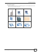
Document Conventions Icons Used in Figures Figures in this User’s Guide may use the following generic icons. The ZyXEL Device icon is not an exact representation of your device.
Safety Warnings Safety Warnings 1 For your safety, be sure to read and follow all warning notices and instructions. • Do NOT use this product near water, for example, in a wet basement or near a swimming pool. • Do NOT expose your device to dampness, dust or corrosive liquids. • Do NOT store things on the device. • Do NOT install, use, or service this device during a thunderstorm. There is a remote risk of electric shock from lightning. • Connect ONLY suitable accessories to the device.
Safety Warnings P-2602H(W)(L)-DxA User’s Guide 7
Safety Warnings 8 P-2602H(W)(L)-DxA User’s Guide
Contents Overview Contents Overview Introduction ............................................................................................................................ 37 Introducing the ZyXEL Device ................................................................................................... 39 Introducing the Web Configurator .............................................................................................. 47 Wizard ...............................................................
Contents Overview 10 P-2602H(W)(L)-DxA User’s Guide
Table of Contents Table of Contents About This User's Guide .......................................................................................................... 3 Document Conventions............................................................................................................ 4 Safety Warnings........................................................................................................................ 6 Contents Overview .......................................................
Table of Contents 2.2.4 Status Bar ................................................................................................................... 53 Part II: Wizard ......................................................................................... 55 Chapter 3 Internet and Wireless Setup Wizard...................................................................................... 57 3.1 Introduction .................................................................................................
Table of Contents 7.1.5 Nailed-Up Connection (PPP) ..................................................................................... 95 7.1.6 NAT ............................................................................................................................ 95 7.2 Metric .................................................................................................................................. 95 7.3 Traffic Shaping .....................................................................
Table of Contents 9.5.2 WEP Encryption Screen ........................................................................................... 123 9.5.3 WPA(2)-PSK ............................................................................................................ 124 9.5.4 WPA(2) Authentication Screen ................................................................................. 125 9.5.5 Wireless LAN Advanced Setup ...............................................................................
Table of Contents 11.3 Quality of Service (QoS) .................................................................................................. 154 11.3.1 Type of Service (ToS) ............................................................................................. 154 11.3.2 DiffServ ................................................................................................................... 154 11.3.3 VLAN Tagging ..............................................................................
Table of Contents 12.8.4 Call Progression ..................................................................................................... 185 12.9 VoIP Trunking Example: PSTN to PSTN via VoIP ........................................................... 185 12.9.1 Background Information ......................................................................................... 186 12.9.2 Configuration Details: Outgoing ............................................................................. 186 12.9.
Table of Contents 15.1 Access Methods .............................................................................................................. 207 15.2 General Firewall Policy Overview ................................................................................... 207 15.3 Rule Logic Overview ....................................................................................................... 208 15.3.1 Rule Checklist ..............................................................................
Table of Contents Chapter 18 VPN Screens.......................................................................................................................... 237 18.1 VPN/IPSec Overview ....................................................................................................... 237 18.2 IPSec Algorithms ............................................................................................................. 237 18.2.1 AH (Authentication Header) Protocol .................................
Table of Contents 19.8 Trusted CAs ................................................................................................................... 273 19.9 Trusted CA Import ......................................................................................................... 275 19.10 Trusted CA Details ......................................................................................................... 276 19.11 Trusted Remote Hosts ...........................................................
Table of Contents 23.3 Telnet ............................................................................................................................... 305 23.4 Configuring Telnet ............................................................................................................ 306 23.5 Configuring FTP ............................................................................................................. 306 23.6 SNMP ....................................................................
Table of Contents 27.1 Introduction ...................................................................................................................... 345 27.2 Filename Conventions ..................................................................................................... 345 27.3 File Maintenance Over WAN ........................................................................................... 346 27.4 Firmware Upgrade Screen ................................................................
Table of Contents Appendix B Setting up Your Computer’s IP Address............................................................ 381 Appendix C Pop-up Windows, JavaScripts and Java Permissions ...................................... 393 Appendix D IP Addresses and Subnetting ........................................................................... 399 Appendix E Wireless LANs .................................................................................................. 407 Appendix F Services ..........
List of Figures List of Figures Figure 1 Internet Access Application ...................................................................................................... 41 Figure 2 Internet Telephony Service Provider Application ...................................................................... 42 Figure 3 Peer-to-peer Calling ................................................................................................................. 42 Figure 4 Firewall Application ............................
List of Figures Figure 39 Wizard: Welcome ................................................................................................................... 78 Figure 40 Bandwidth Management Wizard: General Information ........................................................... 78 Figure 41 Bandwidth Management Wizard: Complete ........................................................................... 79 Figure 42 Status Screen ..............................................................................
List of Figures Figure 82 Port Forwarding Rule Setup ............................................................................................... 144 Figure 83 Address Mapping Rules ....................................................................................................... 145 Figure 84 Edit Address Mapping Rule ................................................................................................ 147 Figure 85 Network > NAT > ALG ....................................................
List of Figures Figure 125 Firewall: Customized Services ........................................................................................... 216 Figure 126 Firewall: Configure Customized Services ........................................................................... 217 Figure 127 Firewall Example: Rules ..................................................................................................... 218 Figure 128 Edit Custom Port Example ...................................................
List of Figures Figure 168 Static Route Edit ................................................................................................................. 289 Figure 169 Subnet-based Bandwidth Management Example .............................................................. 292 Figure 170 Bandwidth Management: General ...................................................................................... 293 Figure 171 Bandwidth Management: Rule Setup .....................................................
List of Figures Figure 211 Configuration Upload Error ................................................................................................. 350 Figure 212 Reset Warning Message .................................................................................................... 350 Figure 213 Reset In Process Message ................................................................................................ 351 Figure 214 Restart Screen .......................................................
List of Figures Figure 254 Configuration Text File Format: Column Descriptions ........................................................ 425 Figure 255 Invalid Parameter Entered: Command Line Example ........................................................ 426 Figure 256 Valid Parameter Entered: Command Line Example ........................................................... 426 Figure 257 Internal SPTGEN FTP Download Example ........................................................................
List of Figures 30 P-2602H(W)(L)-DxA User’s Guide
List of Tables List of Tables Table 1 Models Covered ........................................................................................................................ 39 Table 2 LEDs ......................................................................................................................................... 44 Table 3 Web Configurator Icons in the Title Bar .................................................................................... 50 Table 4 Navigation Panel Summary ...........
List of Tables Table 39 Network > Wireless LAN > OTIST ........................................................................................ 129 Table 40 MAC Address Filter ............................................................................................................... 132 Table 41 Wireless LAN: QoS ............................................................................................................... 133 Table 42 Application Priority Configuration .................................
List of Tables Table 82 Firewall: Configure Customized Services ............................................................................. 217 Table 83 Firewall: Threshold ................................................................................................................ 223 Table 84 Sys Firewall Commands ....................................................................................................... 224 Table 85 Content Filter: Keyword ................................................
List of Tables Table 125 Remote Management: WWW ............................................................................................. 305 Table 126 Remote Management: Telnet .............................................................................................. 306 Table 127 Remote Management: FTP ................................................................................................. 307 Table 128 SNMP Traps ...........................................................................
List of Tables Table 168 Voice Features .................................................................................................................... 376 Table 169 Wireless Features ............................................................................................................... 378 Table 170 IEEE 802.11g ...................................................................................................................... 379 Table 171 P-2602HWL Series Power Adaptor Specifications .....
List of Tables 36 P-2602H(W)(L)-DxA User’s Guide
P ART I Introduction Introducing the ZyXEL Device (39) Introducing the Web Configurator (47) 37
CHAPTER 1 Introducing the ZyXEL Device This chapter introduces the main applications and features of the ZyXEL Device. It also introduces the ways you can manage the ZyXEL Device. 1.1 Overview The P-2602H(W)(L)-DxA series are Integrated Access Devices (IADs) that combine an ADSL2+ router with Voice over IP (VoIP) communication capabilities to allow you to use a traditional analog or ISDN telephone to make Internet calls.
Chapter 1 Introducing the ZyXEL Device • Model names with “3” as the penultimate character (like the P-2602HWL-D3A) denote a device that works over ISDN (Integrated Services Digital Network). Models with “1” as the penultimate character (like the P-2602HWL-D1A) denote a device that works over TISDN (U-R2). 1 " Only use firmware for your ZyXEL Device’s specific model. Refer to the label on the bottom of your ZyXEL Device. All screens displayed in this user’s guide are from the P-2602HWL-D1A model.
Chapter 1 Introducing the ZyXEL Device • Back up the configuration (and make sure you know how to restore it). Restoring an earlier working configuration may be useful if the device becomes unstable or even crashes. If you forget your password, you will have to reset the ZyXEL Device to its factory default settings. If you backed up an earlier configuration file, you would not have to totally re-configure the ZyXEL Device. You could simply restore your last configuration. 1.
Chapter 1 Introducing the ZyXEL Device Figure 2 Internet Telephony Service Provider Application 1.4.3 Make Peer-to-peer Calls You can call directly to someone’s IP address without using a SIP proxy server. Peer-to-peer calls are also called “Point to Point” or “IP-to-IP” calls. You must know the peer’s IP address in order to do this. The following figure shows a basic example of how you would make a peer-to-peer VoIP call.
Chapter 1 Introducing the ZyXEL Device Figure 4 Firewall Application 1.4.5 LAN to LAN Application You can use your device to connect two geographically dispersed networks over the ADSL line. A typical LAN-to-LAN application is shown as follows.
Chapter 1 Introducing the ZyXEL Device 1.5 LEDs Figure 6 LEDs The following table describes your device’s LEDs. Table 2 LEDs LED COLOR STATUS DESCRIPTION POWER Green On Your device is receiving power and functioning properly. Blinking Your device is rebooting and performing a self-test. Red On Your device is not ready or there is a malfunction. None Off Your device is not turned on. Green On Your device has a successful Ethernet connection.
Chapter 1 Introducing the ZyXEL Device Table 2 LEDs (continued) LED COLOR STATUS DESCRIPTION DSL Green On Your device has a DSL connection. Blinking Your device is initializing the DSL line. None Off The DSL link is down. Green On Your device has an IP connection but no traffic. Your device has a WAN IP address (either static or assigned by a DHCP server), PPP negotiation was successfully completed (if used) and the DSL connection is up.
Chapter 1 Introducing the ZyXEL Device To set the device back to the factory default settings, press the RESET button for ten seconds or until the POWER LED begins to blink and then release it. When the POWER LED begins to blink, the defaults have been restored and the device restarts.
CHAPTER 2 Introducing the Web Configurator This chapter describes how to access and navigate the web configurator. 2.1 Web Configurator Overview The web configurator is an HTML-based management interface that allows easy device setup and management via Internet browser. Use Internet Explorer 6.0 and later or Netscape Navigator 7.0 and later versions. The recommended screen resolution is 1024 by 768 pixels.
Chapter 2 Introducing the Web Configurator Figure 7 Password Screen 5 The following screen displays if you have not yet changed your password. It is strongly recommended you change the default password. Enter a new password, retype it to confirm and click Apply; alternatively click Ignore to proceed to the main menu if you do not want to change the password now.
Chapter 2 Introducing the Web Configurator Figure 9 Replace Certificate Screen 7 A screen displays to let you choose whether to go to the wizard or the advanced screens. • Click Go to Wizard setup if you are logging in for the first time or if you want to make basic changes. The wizard selection screen appears after you click Apply. See Chapter 3 on page 57 for more information. • Click Go to Advanced setup if you want to configure features that are not available in the wizards.
Chapter 2 Introducing the Web Configurator 2.2 Web Configurator Main Screen Figure 11 Main Screen B A C D As illustrated above, the main screen is divided into these parts: • • • • A - title bar B - navigation panel C - main window D - status bar 2.2.1 Title Bar The title bar allows you to change the language and provides some icons in the upper right corner. The icons provide the following functions.
Chapter 2 Introducing the Web Configurator 2.2.2 Navigation Panel Use the menu items on the navigation panel to open screens to configure ZyXEL Device features. The following tables describe each menu item. Table 4 Navigation Panel Summary LINK TAB Status FUNCTION This screen contains administrative and system-related information.
Chapter 2 Introducing the Web Configurator Table 4 Navigation Panel Summary LINK TAB FUNCTION Speed Dial Use this screen to configure speed dial for SIP phone numbers that you call often. Incoming Call Policy Use this screen to configure call-forwarding. Distinctive Ring Use this screen to configure ring tone behavior based on the origin of incoming calls. PSTN Line (“L” models only) General Use this screen to configure your ZyXEL Device’s settings for PSTN calls.
Chapter 2 Introducing the Web Configurator Table 4 Navigation Panel Summary LINK TAB Dynamic DNS Remote MGMT UPnP FUNCTION This screen allows you to use a static hostname alias for a dynamic IP address. WWW Use this screen to configure through which interface(s) and from which IP address(es) users can use HTTP to manage the ZyXEL Device. Telnet Use this screen to configure through which interface(s) and from which IP address(es) users can use Telnet to manage the ZyXEL Device.
Chapter 2 Introducing the Web Configurator 54 P-2602H(W)(L)-DxA User’s Guide
P ART II Wizard Internet and Wireless Setup Wizard (57) VoIP Wizard And Example (71) Bandwidth Management Wizard (77) 55
CHAPTER 3 Internet and Wireless Setup Wizard This chapter provides information on the Wizard Setup screens for Internet access in the web configurator. 3.1 Introduction Use the wizard setup screens to configure your system for Internet access with the information given to you by your ISP. " See the advanced menu chapters for background information on these fields. 3.2 Internet Access Wizard Setup 1 After you enter the password to access the web configurator, select Go to Wizard setup and click Apply.
Chapter 3 Internet and Wireless Setup Wizard Figure 12 Select a Mode 2 Click INTERNET/WIRELESS SETUP to configure the system for Internet access and wireless connection. Figure 13 Wizard Welcome 3 Your ZyXEL device attempts to detect your DSL connection and your connection type. 3a The following screen appears if a connection is not detected. Check your hardware connections and click Restart the Internet/Wireless Setup Wizard to return to the wizard welcome screen.
Chapter 3 Internet and Wireless Setup Wizard Figure 14 Auto Detection: No DSL Connection 3b The following screen displays if a PPPoE or PPPoA connection is detected. Enter your Internet account information (username, password and/or service name) exactly as provided by your ISP. Then click Next and see Section 3.3 on page 65 for wireless connection wizard setup. Figure 15 Auto-Detection: PPPoE 3c The following screen appears if the ZyXEL device detects a connection but not the connection type.
Chapter 3 Internet and Wireless Setup Wizard Figure 16 Auto Detection: Failed 3.2.1 Manual Configuration 1 If the ZyXEL Device fails to detect your DSL connection type but the physical line is connected, enter your Internet access information in the wizard screen exactly as your service provider gave it to you. Leave the defaults in any fields for which you were not given information.
Chapter 3 Internet and Wireless Setup Wizard Figure 17 Internet Access Wizard Setup: ISP Parameters The following table describes the fields in this screen. Table 5 Internet Access Wizard Setup: ISP Parameters LABEL DESCRIPTION Mode From the Mode drop-down list box, select Routing (default) if your ISP allows multiple computers to share an Internet account. Otherwise select Bridge. Encapsulation Select the encapsulation type your ISP uses from the Encapsulation drop-down list box.
Chapter 3 Internet and Wireless Setup Wizard Figure 18 Internet Connection with PPPoE The following table describes the fields in this screen. Table 6 LABEL DESCRIPTION User Name Enter the user name exactly as your ISP assigned. If assigned a name in the form user@domain where domain identifies a service name, then enter both components exactly as given. Password Enter the password associated with the user name above. Service Name Type the name of your PPPoE service here.
Chapter 3 Internet and Wireless Setup Wizard The following table describes the fields in this screen. Table 7 Internet Connection with RFC 1483 LABEL DESCRIPTION IP Address This field is available if you select Routing in the Mode field. Type your ISP assigned IP address in this field. Back Click Back to go back to the previous wizard screen. Next Click Next to continue to the next wizard screen. Exit Click Exit to close the wizard screen without saving your changes.
Chapter 3 Internet and Wireless Setup Wizard Table 8 Internet Connection with ENET ENCAP (continued) LABEL DESCRIPTION Apply Click Apply to save your changes back to the ZyXEL Device. Exit Click Exit to close the wizard screen without saving your changes. Figure 21 Internet Connection with PPPoA The following table describes the fields in this screen. Table 9 Internet Connection with PPPoA LABEL DESCRIPTION User Name Enter the login name that your ISP gives you.
Chapter 3 Internet and Wireless Setup Wizard Figure 22 Connection Test Failed-1 • If the following screen displays, check if your account is activated or click Restart the Internet/Wireless Setup Wizard to verify your Internet access settings. Figure 23 Connection Test Failed-2. 3.3 Wireless Connection Wizard Setup After you configure the Internet access information, use the following screens to set up your wireless LAN. 1 Select Yes and click Next to configure wireless settings.
Chapter 3 Internet and Wireless Setup Wizard Figure 24 Connection Test Successful 2 Use this screen to activate the wireless LAN and OTIST. Click Next to continue. Figure 25 Wireless LAN Setup Wizard 1 The following table describes the labels in this screen. Table 10 Wireless LAN Setup Wizard 1 66 LABEL DESCRIPTION Active Select the check box to turn on the wireless LAN.
Chapter 3 Internet and Wireless Setup Wizard 3 Configure your wireless settings in this screen. Click Next. Figure 26 Wireless LAN The following table describes the labels in this screen. Table 11 Wireless LAN Setup Wizard 2 " LABEL DESCRIPTION Network Name(SSID) Enter a descriptive name (up to 32 printable 7-bit ASCII characters) for the wireless LAN. If you change this field on the ZyXEL Device, make sure all wireless stations use the same SSID in order to access the network.
Chapter 3 Internet and Wireless Setup Wizard 3.3.1 Manually Assign a WPA key Choose Manually assign a WPA key in the Wireless LAN setup screen to set up a PreShared Key. Figure 27 Manually Assign a WPA key The following table describes the labels in this screen. Table 12 Manually Assign a WPA key LABEL DESCRIPTION Pre-Shared Key Type from 8 to 63 case-sensitive ASCII characters. You can set up the most secure wireless connection by configuring WPA in the wireless LAN screens.
Chapter 3 Internet and Wireless Setup Wizard The following table describes the labels in this screen. Table 13 Manually Assign a WEP key LABEL DESCRIPTION Key The WEP keys are used to encrypt data. Both the ZyXEL Device and the wireless stations must use the same WEP key for data transmission. Enter any 5, 13 or 29 ASCII characters or 10, 26 or 58 hexadecimal characters ("0-9", "A-F") for a 64-bit, 128-bit or 256-bit WEP key respectively. Back Click Back to display the previous screen.
Chapter 3 Internet and Wireless Setup Wizard Figure 30 Internet Access and WLAN Wizard Setup Complete 7 Launch your web browser and navigate to www.zyxel.com. Internet access is just the beginning. Refer to the rest of this guide for more detailed information on the complete range of ZyXEL Device features. If you cannot access the Internet, open the web configurator again to confirm that the Internet settings you configured in the wizard setup are correct.
CHAPTER 4 VoIP Wizard And Example This chapter shows you how to configure your SIP account(s) and make a VoIP phone call. 4.1 Introduction The ZyXEL Device has Voice over IP (VoIP) communication capabilities that allow you to use a traditional analog telephone to make Internet calls. You can configure the ZyXEL Device to use up to two SIP based VoIP accounts. This section describes how you can set up your ZyXEL Device to call someone who is also using a VoIP device.
Chapter 4 VoIP Wizard And Example Figure 32 Select a Mode 2 Click VOICE OVER INTERNET SETUP to configure your SIP settings. Figure 33 Wizard: Welcome 3 Fill in the VOICE OVER INTERNET SETUP wizard screen with the information provided by your VoIP service provider. Your VoIP service provider supplies you with the following information. When you are finished, click Apply.
Chapter 4 VoIP Wizard And Example Table 14 Sample SIP Account Information INFORMATION FROM VOIP SERVICE PROVIDER EXAMPLE VALUES DESCRIPTION Username VoIPUser This is the username you use to login to your SIP account. Password Password This is the password you use to login to your SIP account. Figure 34 VoIP Wizard Configuration The following table describes the labels in this screen. Table 15 VoIP Wizard Configuration LABEL DESCRIPTION SIP Number Enter your SIP number in this field.
Chapter 4 VoIP Wizard And Example Table 15 VoIP Wizard Configuration LABEL DESCRIPTION Back Click Back to return to the previous screen. Apply Click Apply to complete the wizard setup and save your configuration. Exit Click Exit to close the wizard without saving your settings. 4 Your ZyXEL Device will attempt to register your SIP account with your VoIP service provider. When your account is registered your PHONE 1 light will come on and you are ready to make and receive VoIP phone calls.
Chapter 4 VoIP Wizard And Example Figure 37 VoIP Wizard Finish 7 To call other VoIP users, you need to follow a similar process to ensure that their SIP account is registered and active. After it is registered, they need to provide you with their SIP number. You can use your VoIP service provider’s dialing plan to call SIP numbers. You can also use your VoIP service provider’s dialing plan to call regular phone numbers.
Chapter 4 VoIP Wizard And Example 76 P-2602H(W)(L)-DxA User’s Guide
CHAPTER 5 Bandwidth Management Wizard This chapter shows you how to configure basic bandwidth management using the wizard screens. 5.1 Introduction Bandwidth management allows you to control the amount of bandwidth going out through the ZyXEL Device’s WAN port and prioritize the distribution of the bandwidth according to service bandwidth requirements. This helps keep one service from using all of the available bandwidth and shutting out other users. 5.
Chapter 5 Bandwidth Management Wizard Figure 39 Wizard: Welcome 3 Select Active to allocate bandwidth to packets based on the packet size. Figure 40 Bandwidth Management Wizard: General Information The following fields describe the label in this screen.
Chapter 5 Bandwidth Management Wizard Figure 41 Bandwidth Management Wizard: Complete P-2602H(W)(L)-DxA User’s Guide 79
Chapter 5 Bandwidth Management Wizard 80 P-2602H(W)(L)-DxA User’s Guide
P ART III Advanced Status Screens (83) WAN Setup (93) LAN Setup (105) Wireless LAN (117) Network Address Translation (NAT) Screens (137) Voice (149) VoIP Trunking (175) Phone Usage (191) Firewalls (195) Firewall Configuration (207) Content Filtering (227) Introduction to IPSec (231) VPN Screens (237) Certificates (263) Static Route (287) Bandwidth Management (291) Dynamic DNS Setup (299) Remote Management Configuration (303) Universal Plug-and-Play (UPnP) (313) 81
CHAPTER 6 Status Screens Use the Status screens to look at the current status of the device, system resources, interfaces (LAN and WAN), and SIP accounts. You can also register and unregister SIP accounts. The Status screen also provides detailed information from Any IP and DHCP and statistics from VoIP, bandwidth management, and traffic. 6.1 Status Screen Click Status to open this screen.
Chapter 6 Status Screens Each field is described in the following table. Table 17 Status Screen LABEL DESCRIPTION Refresh Interval Enter how often you want the ZyXEL Device to update this screen. Apply Click this to update this screen immediately. Device Information Host Name This field displays the ZyXEL Device system name. It is used for identification. You can change this in the Maintenance > System > General screen’s System Name field. Model Number This is the model name of your device.
Chapter 6 Status Screens Table 17 Status Screen LABEL DESCRIPTION Security Firewall This displays whether or not the ZyXEL Device’s firewall is activated. Click this to go to the screen where you can change it. Content Filter This displays whether or not the ZyXEL Device’s content filtering is activated. Click this to go to the screen where you can change it. System Status System Uptime This field displays how long the ZyXEL Device has been running since it last started up.
Chapter 6 Status Screens Table 17 Status Screen LABEL DESCRIPTION VPN Status Click this link to view the ZyXEL Device’s current VPN connections. See Section 18.16 on page 257. Packet Statistics Click this link to view port status and packet specific statistics. See Section 6.4 on page 87. VoIP Statistics Click this link to view statistics about your VoIP usage. See Section 6.5 on page 89. VoIP Status Account This column displays each SIP account in the ZyXEL Device.
Chapter 6 Status Screens Each field is described in the following table. Table 18 Any IP Table LABEL DESCRIPTION # This field is a sequential value. It is not associated with a specific entry. IP Address This field displays the IP address of each computer that is using the ZyXEL Device but is in a different subnet than the ZyXEL Device. MAC Address This field displays the MAC address of the computer that is using the ZyXEL Device but is in a different subnet than the ZyXEL Device.
Chapter 6 Status Screens Figure 45 Packet Statistics The following table describes the fields in this screen. Table 20 Packet Statistics LABEL DESCRIPTION System Monitor System up Time This is the elapsed time the system has been up. Current Date/Time This field displays your ZyXEL Device’s present date and time. CPU Usage This field specifies the percentage of CPU utilization. Memory Usage This field specifies the percentage of memory utilization.
Chapter 6 Status Screens Table 20 Packet Statistics (continued) LABEL DESCRIPTION Interface This field displays either Ethernet (LAN ports) or Wireless (WLAN port). Status For the LAN ports, this field displays Down (line is down) or Up (line is up or connected). For the WLAN port, it displays the transmission rate when WLAN is enabled or N/A when WLAN is disabled. TxPkts This field displays the number of packets transmitted on this interface.
Chapter 6 Status Screens Table 21 VoIP Statistics LABEL DESCRIPTION Registration This field displays the current registration status of the SIP account. You can change this in the Status screen. Registered - The SIP account is registered with a SIP server. Register Fail - The last time the ZyXEL Device tried to register the SIP account with the SIP server, the attempt failed. The ZyXEL Device automatically tries to register the SIP account when you turn on the ZyXEL Device or when you activate it.
Chapter 6 Status Screens Table 21 VoIP Statistics LABEL DESCRIPTION Poll Interval(s) Enter how often you want the ZyXEL Device to update this screen, and click Set Interval. Set Interval Click this to make the ZyXEL Device update the screen based on the amount of time you specified in Poll Interval. Stop Click this to make the ZyXEL Device stop updating the screen.
Chapter 6 Status Screens 92 P-2602H(W)(L)-DxA User’s Guide
CHAPTER 7 WAN Setup This chapter describes how to configure WAN settings. 7.1 WAN Overview A WAN (Wide Area Network) is an outside connection to another network or the Internet. 7.1.1 Encapsulation Be sure to use the encapsulation method required by your ISP. The ZyXEL Device supports the following methods. 7.1.1.1 ENET ENCAP The MAC Encapsulated Routing Link Protocol (ENET ENCAP) is only implemented with the IP network protocol.
Chapter 7 WAN Setup 7.1.1.3 PPPoA PPPoA stands for Point to Point Protocol over ATM Adaptation Layer 5 (AAL5). A PPPoA connection functions like a dial-up Internet connection. The ZyXEL Device encapsulates the PPP session based on RFC1483 and sends it through an ATM PVC (Permanent Virtual Circuit) to the Internet Service Provider’s (ISP) DSLAM (Digital Subscriber Line (DSL) Access Multiplexer). Please refer to RFC 2364 for more information on PPPoA. Refer to RFC 1661 for more information on PPP. 7.1.1.
Chapter 7 WAN Setup 7.1.4.1 IP Assignment with PPPoA or PPPoE Encapsulation If you have a dynamic IP, then the IP Address and ENET ENCAP Gateway fields are not applicable (N/A). If you have a static IP, then you only need to fill in the IP Address field and not the ENET ENCAP Gateway field. 7.1.4.2 IP Assignment with RFC 1483 Encapsulation In this case the IP Address Assignment must be static with the same requirements for the IP Address and ENET ENCAP Gateway fields as stated above. 7.1.4.
Chapter 7 WAN Setup For example, if the normal route has a metric of "1" and the traffic-redirect route has a metric of "2" and dial-backup route has a metric of "3", then the normal route acts as the primary default route. If the normal route fails to connect to the Internet, the ZyXEL Device tries the traffic-redirect route next. In the same manner, the ZyXEL Device uses the dial-backup route if the traffic-redirect route also fails.
Chapter 7 WAN Setup 7.3.1 ATM Traffic Classes These are the basic ATM traffic classes defined by the ATM Forum Traffic Management 4.0 Specification. 7.3.1.1 Constant Bit Rate (CBR) Constant Bit Rate (CBR) provides fixed bandwidth that is always available even if no data is being sent. CBR traffic is generally time-sensitive (doesn't tolerate delay). CBR is used for connections that continuously require a specific amount of bandwidth.
Chapter 7 WAN Setup 7.5 Internet Access Setup Use this screen to change your ZyXEL Device’s WAN remote node settings. Click Network > WAN > Internet Access Setup. The screen differs by the encapsulation you select. See Section 7.1 on page 93 for more information. Figure 48 Internet Access Setup (PPPoE) The following table describes the labels in this screen.
Chapter 7 WAN Setup Table 22 Internet Access Setup (continued) LABEL DESCRIPTION Multiplexing Select the method of multiplexing used by your ISP from the drop-down list. Choices are VC or LLC. Virtual Circuit ID VPI (Virtual Path Identifier) and VCI (Virtual Channel Identifier) define a virtual circuit. Refer to the appendix for more information. VPI The valid range for the VPI is 0 to 255. Enter the VPI assigned to you.
Chapter 7 WAN Setup Table 22 Internet Access Setup (continued) LABEL DESCRIPTION Max Idle Timeout Specify an idle time-out in the Max Idle Timeout field when you select Connect on Demand. The default setting is 0, which means the Internet session will not timeout. Apply Click Apply to save the changes. Cancel Click Cancel to begin configuring this screen afresh. Advanced Setup Click this button to display the Advanced WAN Setup screen and edit more details of your WAN setup. 7.5.
Chapter 7 WAN Setup Table 23 Advanced Internet Access Setup (continued) LABEL DESCRIPTION Multicast Multicast packets are sent to a group of computers on the LAN and are an alternative to unicast packets (packets sent to one computer) and broadcast packets (packets sent to every computer). IGMP (Internet Group Multicast Protocol) is a network-layer protocol used to establish membership in a multicast group. The ZyXEL Device supports both IGMP version 1 (IGMP-v1) and IGMP-v2. Select None to disable it.
Chapter 7 WAN Setup Figure 50 WAN More Connections The following table describes the labels in this screen. Table 24 Advanced Internet Access Setup LABEL DESCRIPTION # This is an index number indicating the number of the corresponding connection. Active This field indicates whether the connection is active or not. Name This is the name you gave to the Internet connection.
Chapter 7 WAN Setup The following network topology allows you to avoid triangle route security issues when the backup gateway is connected to the LAN. Use IP alias to configure the LAN into two or three logical networks with the ZyXEL Device itself as the gateway for each LAN network. Put the protected LAN in one subnet (Subnet 1 in the following figure) and the backup gateway in another subnet (Subnet 2).
Chapter 7 WAN Setup The following table describes the labels in this screen. Table 25 WAN Backup Setup LABEL DESCRIPTION Backup Type Select the method that the ZyXEL Device uses to check the DSL connection. Select DSL Link to have the ZyXEL Device check if the connection to the DSLAM is up. Select ICMP to have the ZyXEL Device periodically ping the IP addresses configured in the Check WAN IP Address fields. Check WAN IP Address1-3 Configure this field to test your ZyXEL Device's WAN accessibility.
CHAPTER 8 LAN Setup This chapter describes how to configure LAN settings. 8.1 LAN Overview A Local Area Network (LAN) is a shared communication system to which many computers are attached. A LAN is a computer network limited to the immediate area, usually the same building or floor of a building. The LAN screens can help you configure a LAN DHCP server and manage IP addresses. See Section 8.4 on page 110 to configure the LAN screens. 8.1.
Chapter 8 LAN Setup 8.1.2 DHCP Setup DHCP (Dynamic Host Configuration Protocol, RFC 2131 and RFC 2132) allows individual clients to obtain TCP/IP configuration at start-up from a server. You can configure the ZyXEL Device as a DHCP server or disable it. When configured as a server, the ZyXEL Device provides the TCP/IP configuration for the clients. If you turn DHCP service off, you must have another DHCP server on your LAN, or else the computer must be manually configured. 8.1.2.
Chapter 8 LAN Setup 8.3.1 IP Address and Subnet Mask Similar to the way houses on a street share a common street name, so too do computers on a LAN share one common network number. Where you obtain your network number depends on your particular situation. If the ISP or your network administrator assigns you a block of registered IP addresses, follow their instructions in selecting the IP addresses and the subnet mask.
Chapter 8 LAN Setup 8.3.2 RIP Setup RIP (Routing Information Protocol) allows a router to exchange routing information with other routers. The RIP Direction field controls the sending and receiving of RIP packets. When set to: • Both - the ZyXEL Device will broadcast its routing table periodically and incorporate the RIP information that it receives. • In Only - the ZyXEL Device will not send any RIP packets but will accept all RIP packets received.
Chapter 8 LAN Setup 8.3.4 Any IP Traditionally, you must set the IP addresses and the subnet masks of a computer and the ZyXEL Device to be in the same subnet to allow the computer to access the Internet (through the ZyXEL Device). In cases where your computer is required to use a static IP address in another network, you may need to manually configure the network settings of the computer every time you want to access the Internet via the ZyXEL Device.
Chapter 8 LAN Setup The following lists out the steps taken, when a computer tries to access the Internet for the first time through the ZyXEL Device. 1 When a computer (which is in a different subnet) first attempts to access the Internet, it sends packets to its default gateway (which is not the ZyXEL Device) by looking at the MAC address in its ARP table. 2 When the computer cannot locate the default gateway, an ARP request is broadcast on the LAN.
Chapter 8 LAN Setup Table 26 LAN IP (continued) LABEL DESCRIPTION Cancel Click Cancel to begin configuring this screen afresh. Advanced Setup Click this button to display the Advanced LAN Setup screen and edit more details of your LAN setup. 8.4.1 Configuring Advanced LAN Setup Use this screen to edit your ZyXEL Device's RIP, multicast, any IP and Windows Networking settings. Click the Advanced Setup button in the LAN IP screen. The screen appears as shown.
Chapter 8 LAN Setup Table 27 Advanced LAN Setup (continued) LABEL DESCRIPTION Allow between LAN and WAN Select this check box to forward NetBIOS packets from the LAN to the WAN and from the WAN to the LAN. If your firewall is enabled with the default policy set to block WAN to LAN traffic, you also need to enable the default WAN to LAN firewall rule that forwards NetBIOS traffic. Clear this check box to block all NetBIOS packets going from the LAN to the WAN and from the WAN to the LAN.
Chapter 8 LAN Setup Table 28 DHCP Setup LABEL DESCRIPTION IP Pool Starting Address This field specifies the first of the contiguous addresses in the IP address pool. Pool Size This field specifies the size, or count of the IP address pool. Remote DHCP Server If Relay is selected in the DHCP field above then enter the IP address of the actual remote DHCP server here.
Chapter 8 LAN Setup Figure 58 LAN Client List The following table describes the labels in this screen. Table 29 LAN Client List LABEL DESCRIPTION IP Address Enter the IP address that you want to assign to the computer on your LAN with the MAC address that you will also specify. MAC Address Enter the MAC address of a computer on your LAN. Add Click Add to add a static DHCP entry. # This is the index number of the static IP table entry (row).
Chapter 8 LAN Setup When you use IP alias, you can also configure firewall rules to control access between the LAN's logical networks (subnets). " Make sure that the subnets of the logical networks do not overlap. The following figure shows a LAN divided into subnets A, B, and C. Figure 59 Physical Network & Partitioned Logical Networks Click Network > LAN > IP Alias to open the following screen. Use this screen to change your ZyXEL Device’s IP alias settings.
Chapter 8 LAN Setup The following table describes the labels in this screen. Table 30 LAN IP Alias 116 LABEL DESCRIPTION IP Alias 1, 2 Select the check box to configure another LAN network for the ZyXEL Device. IP Address Enter the IP address of your ZyXEL Device in dotted decimal notation. Alternatively, click the right mouse button to copy and/or paste the IP address. IP Subnet Mask Your ZyXEL Device will automatically calculate the subnet mask based on the IP address that you assign.
CHAPTER 9 Wireless LAN This chapter discusses how to configure the wireless network settings in your ZyXEL Device. See the appendices for more detailed information about wireless networks. This chapter applies to the “W” models only. 9.1 Wireless Network Overview The following figure provides an example of a wireless network. Figure 61 Example of a Wireless Network The wireless network is the part in the blue circle.
Chapter 9 Wireless LAN Like radio stations or television channels, each wireless network uses a specific channel, or frequency, to send and receive information. • Every device in the same wireless network must use security compatible with the AP. Security stops unauthorized devices from using the wireless network. It can also protect the information that is sent in the wireless network. 9.
Chapter 9 Wireless LAN Unauthorized wireless devices can still see the information that is sent in the wireless network, even if they cannot use the wireless network. Furthermore, there are ways for unauthorized wireless users to get a valid user name and password. Then, they can use that user name and password to use the wireless network. 9.2.4 Encryption Wireless networks can use encryption to protect the information that is sent in the wireless network. Encryption is like a secret code.
Chapter 9 Wireless LAN 9.2.5 One-Touch Intelligent Security Technology (OTIST) With ZyXEL’s OTIST, you set up the SSID and the encryption (WEP or WPA-PSK) on the ZyXEL Device. Then, the ZyXEL Device transfers them to the devices in the wireless networks. As a result, you do not have to set up the SSID and encryption on every device in the wireless network. The devices in the wireless network have to support OTIST, and they have to be in range of the ZyXEL Device when you activate it. See Section 9.
Chapter 9 Wireless LAN Table 32 Additional Wireless Terms TERM DESCRIPTION Fragmentation Threshold A small fragmentation threshold is recommended for busy networks, while a larger threshold provides faster performance if the network is not very busy. Roaming If you have two or more ZyXEL Devices (or other wireless access points) on your wireless network, you can enable this option so that wireless devices can change locations without having to log in again.
Chapter 9 Wireless LAN The following table describes the labels in this screen. Table 33 Wireless LAN: General LABEL DESCRIPTION Active Wireless LAN Click the check box to activate wireless LAN. Network Name (SSID) (Service Set IDentity) The SSID identifies the Service Set with which a wireless station is associated. Wireless stations associating to the access point (AP) must have the same SSID. Enter a descriptive name (up to 32 printable 7-bit ASCII characters) for the wireless LAN.
Chapter 9 Wireless LAN Figure 63 Wireless: No Security The following table describes the labels in this screen. Table 34 Wireless No Security LABEL DESCRIPTION Security Mode Choose No Security from the drop-down list box. 9.5.2 WEP Encryption Screen In order to configure and enable WEP encryption; click Network > Wireless LAN to display the General screen. Select Static WEP from the Security Mode list.
Chapter 9 Wireless LAN The following table describes the wireless LAN security labels in this screen. Table 35 Wireless: Static WEP Encryption LABEL DESCRIPTION Security Mode Choose Static WEP from the drop-down list box. Passphrase Enter a Passphrase (up to 32 printable characters) and clicking Generate. The ZyXEL Device automatically generates a WEP key. WEP Key The WEP key is used to encrypt data. Both the ZyXEL Device and the wireless stations must use the same WEP key for data transmission.
Chapter 9 Wireless LAN Table 36 Wireless: WPA(2)-PSK LABEL DESCRIPTION Pre-Shared Key The encryption mechanisms used for WPA(2) and WPA(2)-PSK are the same. The only difference between the two is that WPA(2)-PSK uses a simple common password, instead of user-specific credentials. Type a pre-shared key from 8 to 63 case-sensitive ASCII characters (including spaces and symbols).
Chapter 9 Wireless LAN Figure 66 Wireless: WPA(2) The following table describes the wireless LAN security labels in this screen. Table 37 Wireless: WPA(2) LABEL DESCRIPTION Security Mode Choose WPA or WPA2 from the drop-down list box. WPA Compatible This field is only available for WPA2. Select this if you want the ZyXEL Device to support WPA and WPA2 simultaneously.
Chapter 9 Wireless LAN Table 37 Wireless: WPA(2) LABEL DESCRIPTION Authentication Server IP Address Enter the IP address of the external authentication server in dotted decimal notation. Port Number Enter the port number of the external authentication server. The default port number is 1812. You need not change this value unless your network administrator instructs you to do so with additional information.
Chapter 9 Wireless LAN Table 38 Wireless LAN: Advanced LABEL DESCRIPTION Fragmentation Threshold It is the maximum data fragment size that can be sent. Enter a value between 256 and 2432. If you select the G+ Enhanced checkbox a value of 4096 is displayed. Preamble Select a preamble type from the drop-down list menu. Choices are Long, Short or Dynamic. The default setting is Long. See the appendix for more information. 802.11 Mode Select 802.11b Only to allow only IEEE 802.
Chapter 9 Wireless LAN The following table describes the labels in this screen. Table 39 Network > Wireless LAN > OTIST LABEL DESCRIPTION Setup Key Type a key (password) 8 ASCII characters long. Note: If you change the OTIST setup key in the ZyXEL Device, you must change it on the wireless devices too. Yes! Select this if you want the ZyXEL Device to automatically generate a preshared key for the wireless network.
Chapter 9 Wireless LAN Figure 70 OTIST: Settings You can use the key in this screen to set up WPA-PSK encryption manually for non-OTIST devices in the wireless network. Review the settings, and click OK. The ZyXEL Device begins transferring OTIST settings. The following screens appear in the ZyXEL Device and in the wireless devices. Figure 71 OTIST: In Progress on the ZyXEL Device Figure 72 OTIST: In Progress on the Wireless Device These screens close when the transfer is complete. 9.6.
Chapter 9 Wireless LAN Figure 73 Start OTIST? 2 If an OTIST-enabled wireless device loses its wireless connection for more than ten seconds, it will search for an OTIST-enabled AP for up to one minute. (If you manually have the wireless device search for an OTIST-enabled AP, there is no timeout; click Cancel in the OTIST progress screen to stop the search.
Chapter 9 Wireless LAN Figure 74 MAC Address Filter The following table describes the labels in this screen. Table 40 MAC Address Filter 132 LABEL DESCRIPTION Active MAC Filter Select the check box to enable MAC address filtering. Filter Action Define the filter action for the list of MAC addresses in the MAC Address table.
Chapter 9 Wireless LAN 9.8 QoS Screen The QoS screen allows you to automatically give a service (such as e-mail, VoIP or FTP) a priority level. Click Network > Wireless LAN > QoS. The following screen displays. Figure 75 Wireless LAN: QoS The following table describes the fields in this screen. Table 41 Wireless LAN: QoS LABEL DESCRIPTION QoS Setup Enable WMM QoS Select the check box to enable WMM QoS on the ZyXEL Device.
Chapter 9 Wireless LAN Table 41 Wireless LAN: QoS LABEL DESCRIPTION Priority This field displays the priority of the application. Highest - Typically used for voice or video that should be high-quality. High - Typically used for voice or video that can be medium-quality. Mid - Typically used for applications that do not fit into another priority. For example, Internet surfing.
Chapter 9 Wireless LAN Table 42 Application Priority Configuration LABEL DESCRIPTION Service The following is a description of the applications you can prioritize with WMM QoS. Select a service from the drop-down list box. • E-Mail Electronic mail consists of messages sent through a computer network to specific groups or individuals.
Chapter 9 Wireless LAN 136 P-2602H(W)(L)-DxA User’s Guide
CHAPTER 10 Network Address Translation (NAT) Screens This chapter discusses how to configure NAT on the ZyXEL Device. 10.1 NAT General Overview NAT (Network Address Translation - NAT, RFC 1631) is the translation of the IP address of a host in a packet, for example, the source address of an outgoing packet, used within one network to a different IP address known within another network. 10.1.
Chapter 10 Network Address Translation (NAT) Screens 10.1.2 What NAT Does In the simplest form, NAT changes the source IP address in a packet received from a subscriber (the inside local address) to another (the inside global address) before forwarding the packet to the WAN side. When the response comes back, NAT translates the destination address (the inside global address) back to the inside local address before forwarding it to the original inside host.
Chapter 10 Network Address Translation (NAT) Screens Figure 78 NAT Application With IP Alias 10.1.5 NAT Mapping Types NAT supports five types of IP/port mapping. They are: • One to One: In One-to-One mode, the ZyXEL Device maps one local IP address to one global IP address. • Many to One: In Many-to-One mode, the ZyXEL Device maps multiple local IP addresses to one global IP address.
Chapter 10 Network Address Translation (NAT) Screens The following table summarizes these types. Table 44 NAT Mapping Types TYPE IP MAPPING One-to-One ILA1ÅÆ IGA1 Many-to-One (SUA/PAT) ILA1ÅÆ IGA1 ILA2ÅÆ IGA1 … Many-to-Many Overload ILA1ÅÆ IGA1 ILA2ÅÆ IGA2 ILA3ÅÆ IGA1 ILA4ÅÆ IGA2 … Many-to-Many No Overload ILA1ÅÆ IGA1 ILA2ÅÆ IGA2 ILA3ÅÆ IGA3 … Server Server 1 IPÅÆ IGA1 Server 2 IPÅÆ IGA1 Server 3 IPÅÆ IGA1 10.
Chapter 10 Network Address Translation (NAT) Screens Figure 79 NAT General The following table describes the labels in this screen. Table 45 NAT General LABEL DESCRIPTION Active Network Address Translation (NAT) Select this check box to enable NAT. SUA Only Select this radio button if you have just one public WAN IP address for your ZyXEL Device. Full Feature Select this radio button if you have multiple public WAN IP addresses for your ZyXEL Device.
Chapter 10 Network Address Translation (NAT) Screens Many residential broadband ISP accounts do not allow you to run any server processes (such as a Web or FTP server) from your location. Your ISP may periodically check for servers and may suspend your account if it discovers any active services at your location. If you are unsure, refer to your ISP. 10.4.1 Default Server IP Address In addition to the servers for specified services, NAT supports a default server IP address.
Chapter 10 Network Address Translation (NAT) Screens 10.5 Configuring Port Forwarding " If you do not assign a Default Server IP address, the ZyXEL Device discards all packets received for ports that are not specified here or in the remote management setup. Click Network > NAT > Port Forwarding to open the following screen. This screen is available only when you select SUA only in the NAT > General screen. See Appendix F on page 417 for port numbers commonly used for particular services.
Chapter 10 Network Address Translation (NAT) Screens Table 46 Port Forwarding LABEL DESCRIPTION Server IP Address This is the server’s IP address. Modify Click the edit icon to go to the screen where you can edit the port forwarding rule. Click the delete icon to delete an existing port forwarding rule. Note that subsequent address mapping rules move up by one when you take this action. Apply Click Apply to save your changes back to the ZyXEL Device.
Chapter 10 Network Address Translation (NAT) Screens 10.6 Address Mapping Note: The Address Mapping screen is available only when you select Full Feature in the NAT > General screen. Ordering your rules is important because the ZyXEL Device applies the rules in the order that you specify. When a rule matches the current packet, the ZyXEL Device takes the corresponding action and the remaining rules are ignored.
Chapter 10 Network Address Translation (NAT) Screens Table 48 Address Mapping Rules (continued) LABEL DESCRIPTION Type 1-1: One-to-one mode maps one local IP address to one global IP address. Note that port numbers do not change for the One-to-one NAT mapping type. M-1: Many-to-One mode maps multiple local IP addresses to one global IP address. This is equivalent to SUA (i.e., PAT, port address translation), ZyXEL's Single User Account feature that previous ZyXEL routers supported only.
Chapter 10 Network Address Translation (NAT) Screens Figure 84 Edit Address Mapping Rule The following table describes the fields in this screen. Table 49 Edit Address Mapping Rule LABEL DESCRIPTION Type Choose the port mapping type from one of the following. One-to-One: One-to-One mode maps one local IP address to one global IP address. Note that port numbers do not change for One-to-one NAT mapping type. Many-to-One: Many-to-One mode maps multiple local IP addresses to one global IP address.
Chapter 10 Network Address Translation (NAT) Screens 10.6.2 SIP ALG Some NAT routers may include a SIP Application Layer Gateway (ALG). A SIP ALG allows SIP calls to pass through NAT by examining and translating IP addresses embedded in the data stream. When the ZyXEL Device registers with the SIP register server, the SIP ALG translates the ZyXEL Device’s private IP address inside the SIP data stream to a public IP address.
CHAPTER 11 Voice This chapter provides background information on VoIP and SIP and explains how to configure your device’s voice settings. 11.1 Introduction to VoIP VoIP is the sending of voice signals over Internet Protocol. This allows you to make phone calls and send faxes over the Internet at a fraction of the cost of using the traditional circuitswitched telephone network. You can also use servers to run telephone service applications like PBX services and voice mail.
Chapter 11 Voice 11.2.1.2 SIP Service Domain The SIP service domain of the VoIP service provider is the domain name in a SIP URI. For example, if the SIP address is 1122334455@VoIP-provider.com, then “VoIP-provider.com” is the SIP service domain. 11.2.2 SIP Call Progression The following figure displays the basic steps in the setup and tear down of a SIP call. A calls B. Table 51 SIP Call Progression A B 1. INVITE 2. Ringing 3. OK 4. ACK 5.Dialogue (voice traffic) 6. BYE 7.
Chapter 11 Voice Figure 86 SIP User Agent 11.2.3.2 SIP Proxy Server A SIP proxy server receives requests from clients and forwards them to another server. In the following example, you want to use client device A to call someone who is using client device C. 1 The client device (A in the figure) sends a call invitation to the SIP proxy server (B). 2 The SIP proxy server forwards the call invitation to C. Figure 87 SIP Proxy Server 11.2.3.
Chapter 11 Voice Figure 88 SIP Redirect Server 11.2.3.4 SIP Register Server A SIP register server maintains a database of SIP identity-to-IP address (or domain name) mapping. The register server checks your user name and password when you register. 11.2.4 RTP When you make a VoIP call using SIP, the RTP (Real time Transport Protocol) is used to handle voice data transfer. See RFC 1889 for details on RTP. 11.2.
Chapter 11 Voice • G.729 is an Analysis-by-Synthesis (AbS) hybrid waveform codec that uses a filter based on information about how the human vocal tract produces sounds. G.729 provides good sound quality and reduces the required bandwidth to 8 kbps. 11.2.7 PSTN Call Setup Signaling Dual-Tone MultiFrequency (DTMF) signaling uses pairs of frequencies (one lower frequency and one higher frequency) to set up calls. It is also known as Touch Tone®.
Chapter 11 Voice 1 Pick up the phone and press “****” on your phone’s keypad and wait for the message that says you are in the configuration menu. 2 Press a number from 1201~1208 followed by the “#” key to listen to the tone. 3 You can continue to add, listen to, or delete tones, or you can hang up the receiver when you are done. 11.2.9.
Chapter 11 Voice Figure 89 DiffServ: Differentiated Service Field DSCP (6-bit) Unused (2-bit) The DSCP value determines the forwarding behavior, the PHB (Per-Hop Behavior), that each packet gets across the DiffServ network. Based on the marking rule, different kinds of traffic can be marked for different priorities of forwarding. Resources can then be allocated according to the DSCP values and the configured policies. 11.3.
Chapter 11 Voice Each field is described in the following table. Table 53 SIP > SIP Settings LABEL DESCRIPTION SIP Account Select the SIP account you want to see in this screen. If you change this field, the screen automatically refreshes. SIP Settings Active SIP Account Select this if you want the ZyXEL Device to use this account. Clear it if you do not want the ZyXEL Device to use this account. Number Enter your SIP number. In the full SIP URI, this is the part before the @ symbol.
Chapter 11 Voice Figure 91 VoIP > SIP Settings > Advanced Each field is described in the following table. Table 54 VoIP > SIP Settings > Advanced LABEL DESCRIPTION SIP Account This field displays the SIP account you see in this screen.
Chapter 11 Voice Table 54 VoIP > SIP Settings > Advanced LABEL DESCRIPTION URL Type Select whether or not to include the SIP service domain name when the ZyXEL Device sends the SIP number. SIP - include the SIP service domain name. TEL - do not include the SIP service domain name. Expiration Duration Enter the number of seconds your SIP account is registered with the SIP register server before it is deleted.
Chapter 11 Voice Table 54 VoIP > SIP Settings > Advanced LABEL DESCRIPTION Enable Select this if your VoIP service provider has a SIP outbound server to handle voice calls. This allows the ZyXEL Device to work with any type of NAT router and eliminates the need for STUN or a SIP ALG. Turn off any SIP ALG on a NAT router in front of the ZyXEL Device to keep it from retranslating the IP address (since this is already handled by the outbound proxy server).
Chapter 11 Voice 11.6 SIP QoS Screen Use this screen to maintain ToS and VLAN settings for the ZyXEL Device. To access this screen, click VoIP > SIP > QoS. Figure 92 SIP > QoS Each field is described in the following table. Table 55 SIP > QoS LABEL DESCRIPTION SIP TOS Priority Setting Enter the priority for SIP voice transmissions. The ZyXEL Device creates Type of Service priority tags with this priority to voice traffic that it transmits.
Chapter 11 Voice 11.7.2 Comfort Noise Generation When using VAD, the ZyXEL Device generates comfort noise when the other party is not speaking. The comfort noise lets you know that the line is still connected as total silence could easily be mistaken for a lost connection. 11.7.3 Echo Cancellation G.168 is an ITU-T standard for eliminating the echo caused by the sound of your voice reverberating in the telephone receiver while you talk. 11.
Chapter 11 Voice Table 56 Phone > Analog Phone LABEL DESCRIPTION PSTN Line (“L” models only) Select this if you want to receive phone calls from the PSTN line (that do not use the Internet) on this phone port. If you select more than one source for incoming calls, there is no way to distinguish between them when you receive phone calls. Note: When the ZyXEL Device does not have power, regardless of the settings you configure, only the phone connected to the PHONE 1 port can be used for making calls.
Chapter 11 Voice Each field is described in the following table. Table 57 Phone > Analog Phone > Advanced LABEL DESCRIPTION Analog Phone Select Phone1 or Phone2 in this field to configure each analog phone port. Voice Volume Control Speaking Volume Enter the loudness that the ZyXEL Device uses for speech that it sends to the peer device. -1 is the quietest, and 1 is the loudest. Listening Volume Enter the loudness that the ZyXEL Device uses for speech that it receives from the peer device.
Chapter 11 Voice Figure 95 Phone > Common Each field is described in the following table. Table 58 Phone > Common LABEL DESCRIPTION Immediate Dial Active Immediate Dial Select this if you want to use the pound key (#) to tell the ZyXEL Device to make the phone call immediately, instead of waiting the number of seconds you selected in the Dialing Interval Select in VoIP > Phone > Analog Phone. If you select this, dial the phone number, and then press the pound key.
Chapter 11 Voice • • • • " Three-Way Conference Internal Calls Call Park and Pickup Do not Disturb To take full advantage of the supplementary phone services available through the ZyXEL Device's phone ports, you may need to subscribe to the services from your VoIP service provider. 11.11.1 The Flash Key Flashing means to press the hook for a short period of time (a few hundred milliseconds) before releasing it.
Chapter 11 Voice If you have another call, press the flash key and then “2” to switch back and forth between caller A and B by putting either one on hold. Press the flash key and then “0” to disconnect the call presently on hold and keep the current call on line. Press the flash key and then “1” to disconnect the current call and resume the call on hold. If you hang up the phone but a caller is still on hold, there will be a remind ring. 11.11.2.
Chapter 11 Voice After pressing the flash key, if you do not issue the sub-command before the default subcommand timeout (2 seconds) expires or issue an invalid sub-command, the current operation will be aborted. Table 60 USA Flash Key Commands COMMAND SUB-COMMAND Flash Flash DESCRIPTION Put a current call on hold to place a second call. After the second call is successful, press the flash key again to have a three-way conference call. Put a current call on hold to answer an incoming call.
Chapter 11 Voice 11.12 Phone Region Screen Use this screen to maintain settings that depend on which region of the world the ZyXEL Device is in. To access this screen, click VoIP > Phone > Region. Figure 96 VoIP > Phone > Region Each field is described in the following table. Table 61 VoIP > Phone > Region LABEL DESCRIPTION Region Settings Select the place in which the ZyXEL Device is located.
Chapter 11 Voice Figure 97 Phone Book > Speed Dial Each field is described in the following table. Table 62 Phone Book > Speed Dial LABEL DESCRIPTION Speed Dial Use this section to create or edit speed-dial entries. # Select the speed-dial number you want to use for this phone number. Number Enter the SIP number you want the ZyXEL Device to call when you dial the speeddial number. Name Enter a name to identify the party you call when you dial the speed-dial number.
Chapter 11 Voice Table 62 Phone Book > Speed Dial LABEL DESCRIPTION Modify Use this field to edit or erase the speed-dial entry. Click the Edit icon to copy the information for this speed-dial entry into the Speed Dial section, where you can change it. Click the Remove icon to erase this speed-dial entry. Clear Click this to erase all the speed-dial entries. Cancel Click this to set every field in this screen to its last-saved value. 11.
Chapter 11 Voice You can create two sets of call-forwarding rules. Each one is stored in a call-forwarding table. Each field is described in the following table. Table 63 Phone Book > Incoming Call Policy LABEL DESCRIPTION Table Number Select the call-forwarding table you want to see in this screen. If you change this field, the screen automatically refreshes.
Chapter 11 Voice 11.15 Distinctive Ring Screen This screen lets you specify ring types for calls from particular numbers. The ring types vary by ring duration and stop ring duration (the time gap between the rings). Any standard phone is compatible with this feature. When an incoming call comes in, the ZyXEL Device checks whether it is from any of the phone numbers you set up in this screen. If the number matches an enabled entry, the ZyXEL Device sends the corresponding ring to your phone.
Chapter 11 Voice Table 64 Phone Book > Distinctive Ring LABEL DESCRIPTION Test Click this to listen to the ring. All the phones connected to the ZyXEL Device ring when you click this button. Ring Selection by Incoming Number Use this section to first assign rings to groups and then assign phone numbers to those groups. Family Select the ring for callers in your family group. Workmate Select the ring for callers in your workmate group. Friend Select the ring for callers in your friend group.
Chapter 11 Voice You can also use the PSTN Line screen to specify phone numbers that should always use the regular phone service (without having to dial a prefix number). Do this for emergency numbers (like those for contacting police, fire or emergency medical services). 11.17 PSTN Line Screen (“L” models only) Use this screen to set up the PSTN line you use to make regular phone calls. To access this screen, click VoIP > PSTN Line > General.
CHAPTER 12 VoIP Trunking Use these screens to configure VoIP trunking on your ZyXEL Device. 12.1 VoIP Trunking Overview VoIP trunking connects an IP network (like the Internet) and the Public Switched Telephone Network (PSTN). PSTN includes the world’s circuit-switched telephone network which is composed of fixed and mobile telephones.
Chapter 12 VoIP Trunking Other settings controlled by the auto attendant include a time limit to decide whether you want to forward a call from the ZyXEL Device or call the phone directly connected to the ZyXEL Device. When you call into your ZyXEL Device you can request to forward a call to another phone number simply by dialing that number. If you don’t dial any number within a specified time limit (for example 5 seconds) then the phone directly connected to the ZyXEL Device rings.
Chapter 12 VoIP Trunking 12.3 Call Rules Call rules automate the forwarding of calls, first to a remote peer device and then to PSTN phones. This is used when you make frequent calls to several PSTN numbers in the same geographic area that start with the same numbers (for example an area code). If there is a remote peer device in that area, you can set up a VoIP link to it and have it forward the calls to PSTN phones. This works by configuring a pattern that the ZyXEL Device can recognize.
Chapter 12 VoIP Trunking Figure 103 PSTN Phone To VoIP Phone 12.4.3 PSTN Phone To PSTN Phone via VoIP A PSTN phone A makes a call to the ZyXEL Device B. B connects to a peer device C and C forwards the call to a PSTN phone D. Figure 104 PSTN Phone To PSTN Phone via VoIP 12.5 Trunking General Screen Use this screen to enable VoIP trunking. Click VoIP > Trunking > General.
Chapter 12 VoIP Trunking Each field is described in the following table. Table 68 VoIP > Trunking > General LABEL DESCRIPTION Enable Trunking Select this to turn on VoIP trunking on your ZyXEL Device. Auto Attendant Timeout This is the setting which determines how long the ZyXEL Device waits for a caller to enter a phone number when it receives the call. Enter the number of seconds before the Auto Attendant times out. The default value is 10 seconds and entering 0 does not change the default.
Chapter 12 VoIP Trunking Figure 106 VoIP > Trunking > Peer Call Each field is described in the following table. Table 69 VoIP > Trunking > Peer Call 180 LABEL DESCRIPTION Outgoing Authentication You need to set up accounts for the peer devices you use in VoIP trunking. This is the IP address of the remote peer device, as well as the username and password needed to authenticate with the remote peer device. # This is an index number of your outgoing authentication accounts.
Chapter 12 VoIP Trunking Table 69 VoIP > Trunking > Peer Call (continued) LABEL DESCRIPTION Password Enter the corresponding password for the username you entered. The remote peer device must have the same password in an incoming authentication entry in order to authenticate your connection. Enter up to 32 alphanumeric characters. Peer IP Enter the IP address of the remote peer device which you want to connect to.
Chapter 12 VoIP Trunking Figure 107 VoIP > Trunking > Call Rule Each field is described in the following table. Table 70 VoIP > Trunking > Call Rule 182 LABEL DESCRIPTION # This is a read-only index number of the call rules. Pattern A Pattern is used when you call your ZyXEL Device from a PSTN phone and want to use it to create a VoIP link to a remote peer device which will forward the call to a PSTN phone.
Chapter 12 VoIP Trunking 12.8 VoIP Trunking Example: VoIP to PSTN This example shows how to configure VoIP to PSTN trunking to save on long distance calls. 12.8.1 Background Information A company has its headquarters in city A and a branch office in city B. The headquarters often needs to call salespeople employed at the branch office. The sales employees often work away from the office and have PSTN phones (mobile or land based).
Chapter 12 VoIP Trunking Figure 109 VoIP to PSTN Example - Speed Dial Screen 2 An outgoing authentication account needs to be configured. This account consists of the IP address and port number of the branch office ZyXEL Device as well as the username and password for authentication. This username and password must match the incoming authentication account username and password on the branch office ZyXEL Device. The name of this rule is “CityB” referring to the branch office ZyXEL Device.
Chapter 12 VoIP Trunking Figure 111 VoIP to PSTN Example - Incoming Authentication 12.8.4 Call Progression The advantage of this kind of VoIP trunking is that once all the configuration is completed, the caller just has to dial a speed dial entry from a phone connected to their ZyXEL Device and the peer devices take care of the rest. This is what happens when headquarters wants to call their Sales1 employee, which is the first entry in the speed dial screen.
Chapter 12 VoIP Trunking 12.9.1 Background Information A company has its headquarters in two different cities. The sales manager (A) from headquarters often needs to call salespeople (D) employed at the branch office. The sales manager often works away from the headquarters office and the sales employees often work away from the branch office. The sales manager and the sales employees have PSTN phones (mobile or land based). The two offices have VoIP trunking devices.
Chapter 12 VoIP Trunking Figure 113 PSTN to PSTN Example: General Configuration 2 An outgoing authentication account needs to be configured. This account consists of the IP address and port number of the branch office ZyXEL Device as well as the username and password for authentication. This username and password must match the incoming authentication account username and password on the branch office ZyXEL Device. The name of this account is “CityB” referring to the branch office ZyXEL Device.
Chapter 12 VoIP Trunking Figure 115 PSTN to PSTN Example - Call Rule 12.9.3 Configuration Details: Incoming The branch office ZyXEL Device needs to have an incoming authentication account configured. This consists of a username and password. This account must match the username and password of the outgoing authentication account of the headquarters’ ZyXEL Device. This can be configured in the VoIP > Trunking > Peer Call screen. Figure 116 PSTN to PSTN Example - Incoming Authentication To Device C 12.9.
Chapter 12 VoIP Trunking Table 72 PSTN to PSTN: VoIP Trunking Call Progression MANAGER HEADQUARTERS BRANCH OFFICE SALES1 The manager dials the PSTN number of the headquarters’ ZyXEL Device. (222-222-2222) The ZyXEL Device receives the call and sends a ringback alert tone to indicate to the caller that VoIP trunking is enabled. The manager dials the PSTN number of Sales1 (555-5551234). The ZyXEL Device prompts the manager to enter the PIN in order to allow VoIP trunking.
Chapter 12 VoIP Trunking 190 P-2602H(W)(L)-DxA User’s Guide
CHAPTER 13 Phone Usage This chapter describes how to use a phone connected to your ZyXEL Device for basic tasks. " Not all service providers support all features. 13.1 Dialing a Telephone Number The PHONE LED turns green when your SIP account is registered. Dial a SIP number like “12345” on your phone’s keypad. Use speed dial entries (see Section 11.13 on page 168) for peer-to-peer calls or SIP numbers that use letters. Dial the speed dial entry on your telephone’s keypad.
Chapter 13 Phone Usage 13.5 Checking the ZyXEL Device’s IP Address Do the following to listen to the ZyXEL Device’s current IP address. 1 Pick up your phone’s receiver. 2 Press “****” on your phone’s keypad and wait for the message that says you are in the configuration menu. 3 Press “5” followed by the # key. 4 Listen to the IP address and make a note of it. 5 Hang up the receiver. 13.
Chapter 13 Phone Usage Table 73 Phone Functions Summary ACTI ON FUNCTION DESCRIPTION *98# Call transfer Transfer a call to another phone. See Section 11.11.2 on page 165 (Europe type) and Section 11.11.3 on page 166 (USA type). *97# Call park #97# Call pickup Use these to place a call on hold on one phone and then continue it on another (if supported by your service provider). See Appendix A on page 375. *66# Call return Place a call to the last person who called you.
Chapter 13 Phone Usage 194 P-2602H(W)(L)-DxA User’s Guide
CHAPTER 14 Firewalls This chapter gives some background information on firewalls and introduces the ZyXEL Device firewall. 14.1 Firewall Overview Originally, the term “firewall” referred to a construction technique designed to prevent the spread of fire from one room to another. The networking term “firewall” is a system or group of systems that enforces an access-control policy between two networks. It may also be defined as a mechanism used to protect a trusted network from an untrusted network.
Chapter 14 Firewalls 14.2.2 Application-level Firewalls Application-level firewalls restrict access by serving as proxies for external servers. Since they use programs written for specific Internet services, such as HTTP, FTP and telnet, they can evaluate network packets for valid application-specific data.
Chapter 14 Firewalls 14.3.1 Denial of Service Attacks Figure 117 Firewall Application 14.4 Denial of Service Denials of Service (DoS) attacks are aimed at devices and networks with a connection to the Internet. Their goal is not to steal information, but to disable a device or network so users no longer have access to network resources. The ZyXEL Device is pre-configured to automatically detect and thwart all known DoS attacks. 14.4.
Chapter 14 Firewalls 14.4.2 Types of DoS Attacks There are four types of DoS attacks: 1 2 3 4 5 Those that exploit bugs in a TCP/IP implementation. Those that exploit weaknesses in the TCP/IP specification. Brute-force attacks that flood a network with useless data. IP Spoofing. "Ping of Death" and "Teardrop" attacks exploit bugs in the TCP/IP implementations of various computer and host systems.
Chapter 14 Firewalls Figure 119 SYN Flood • In a LAND Attack, hackers flood SYN packets into the network with a spoofed source IP address of the targeted system. This makes it appear as if the host computer sent the packets to itself, making the system unavailable while the target system tries to respond to itself. 7 A brute-force attack, such as a "Smurf" attack, targets a feature in the IP specification known as directed or subnet broadcasting, to quickly flood the target network with useless data.
Chapter 14 Firewalls 14.4.2.1 ICMP Vulnerability ICMP is an error-reporting protocol that works in concert with IP. The following ICMP types trigger an alert: Table 75 ICMP Commands That Trigger Alerts 5 REDIRECT 13 TIMESTAMP_REQUEST 14 TIMESTAMP_REPLY 17 ADDRESS_MASK_REQUEST 18 ADDRESS_MASK_REPLY 14.4.2.2 Illegal Commands (NetBIOS and SMTP) The only legal NetBIOS commands are the following - all others are illegal.
Chapter 14 Firewalls are allowed in. The ZyXEL Device uses stateful packet inspection to protect the private LAN from hackers and vandals on the Internet. By default, the ZyXEL Device’s stateful inspection allows all communications to the Internet that originate from the LAN, and blocks all traffic to the LAN that originates from the Internet. In summary, stateful inspection: • Allows all sessions originating from the LAN (local network) to the WAN (Internet).
Chapter 14 Firewalls 6 Later, an inbound packet reaches the interface. This packet is part of the connection previously established with the outbound packet. The inbound packet is evaluated against the inbound access list, and is permitted because of the temporary access list entry previously created. 7 The packet is inspected by a firewall rule, and the connection's state table entry is updated as necessary.
Chapter 14 Firewalls If an initiation packet originates on the LAN, this means that someone is trying to make a connection from the LAN to the Internet. Assuming that this is an acceptable part of the security policy (as is the case with the default policy), the connection will be allowed. A cache entry is added which includes connection information such as IP addresses, TCP ports, sequence numbers, etc.
Chapter 14 Firewalls 14.6 Guidelines for Enhancing Security with Your Firewall • Change the default password. • Limit who can telnet into your router. • Don't enable any local service (such as SNMP or NTP) that you don't use. Any enabled service could present a potential security risk. A determined hacker might be able to find creative ways to misuse the enabled services to access the firewall or the network. • For local services that are enabled, protect against misuse.
Chapter 14 Firewalls • Always shred confidential information, particularly about your computer, before throwing it away. Some hackers dig through the trash of companies or individuals for information that might help them in an attack. 14.7 Packet Filtering Vs Firewall Below are some comparisons between the ZyXEL Device’s filtering and firewall functions. 14.7.1 Packet Filtering: • The router filters packets as they pass through the router’s interface according to the filter rules you designed.
Chapter 14 Firewalls • To selectively block/allow inbound or outbound traffic between inside host/networks and outside host/networks. Remember that filters can not distinguish traffic originating from an inside host or an outside host by IP address. • The firewall performs better than filtering if you need to check many rules. • Use the firewall if you need routine e-mail reports about your system or need to be alerted when attacks occur.
CHAPTER 15 Firewall Configuration This chapter shows you how to enable and configure the ZyXEL Device firewall. 15.1 Access Methods The web configurator is, by far, the most comprehensive firewall configuration tool your ZyXEL Device has to offer. For this reason, it is recommended that you configure your firewall using the web configurator. CLI commands provide limited configuration options and are only recommended for advanced users. 15.
Chapter 15 Firewall Configuration You may define additional rules and sets or modify existing ones but please exercise extreme caution in doing so. " If you configure firewall rules without a good understanding of how they work, you might inadvertently introduce security risks to the firewall and to the protected network. Make sure you test your rules after you configure them.
Chapter 15 Firewall Configuration 2 Does this rule stop LAN users from accessing critical resources on the Internet? For example, if IRC is blocked, are there users that require this service? 3 Is it possible to modify the rule to be more specific? For example, if IRC is blocked for all users, will a rule that blocks just certain users be more effective? 4 Does a rule that allows Internet users access to resources on the LAN create a security vulnerability? For example, if FTP ports (TCP 20, 21) are allowe
Chapter 15 Firewall Configuration 15.4.1 LAN to WAN Rules The default rule for LAN to WAN traffic is that all users on the LAN are allowed nonrestricted access to the WAN. When you configure a LAN to WAN rule, you in essence want to limit some or all users from accessing certain services on the WAN. WAN to LAN Rules The default rule for WAN to LAN traffic blocks all incoming connections (WAN to LAN).
Chapter 15 Firewall Configuration The following table describes the labels in this screen. Table 78 Firewall: General LABEL DESCRIPTION Active Firewall Select this check box to activate the firewall. The ZyXEL Device performs access control and protects against Denial of Service (DoS) attacks when the firewall is activated. Bypass Triangle Route Select this check box to have the ZyXEL Device firewall permit the use of triangle route topology on the network.
Chapter 15 Firewall Configuration Figure 123 Firewall Rules The following table describes the labels in this screen. Table 79 Firewall Rules LABEL DESCRIPTION Firewall Rules Storage Space in Use This read-only bar shows how much of the ZyXEL Device's memory for recording firewall rules it is currently using. When you are using 80% or less of the storage space, the bar is green. When the amount of space used is over 80%, the bar is red.
Chapter 15 Firewall Configuration Table 79 Firewall Rules (continued) LABEL DESCRIPTION Modify Click the Edit icon to go to the screen where you can edit the rule. Click the Remove icon to delete an existing firewall rule. A window displays asking you to confirm that you want to delete the firewall rule. Note that subsequent firewall rules move up by one when you take this action. Order Click the Move icon to display the Move the rule to field.
Chapter 15 Firewall Configuration Figure 124 Firewall: Edit Rule The following table describes the labels in this screen. Table 80 Firewall: Edit Rule 214 LABEL DESCRIPTION Active Select this option to enable this firewall rule. Action for Matched Packet Use the drop-down list box to select whether to discard (Drop), deny and send an ICMP destination-unreachable message to the sender of (Reject) or allow the passage of (Permit) packets that match this rule.
Chapter 15 Firewall Configuration Table 80 Firewall: Edit Rule (continued) LABEL DESCRIPTION Source/Destination Address Address Type Do you want your rule to apply to packets with a particular (single) IP, a range of IP addresses (for instance, 192.168.1.10 to 192.169.1.50), a subnet or any IP address? Select an option from the drop-down list box that includes: Single Address, Range Address, Subnet Address and Any Address.
Chapter 15 Firewall Configuration 15.6.2 Customized Services Configure customized services and port numbers not predefined by the ZyXEL Device. For a comprehensive list of port numbers and services, visit the IANA (Internet Assigned Number Authority) website. See Appendix F on page 417 for some examples. Click the Edit Customized Services link while editing a firewall rule to configure a custom service port. This displays the following screen. Refer to Section 14.1 on page 195 for more information.
Chapter 15 Firewall Configuration Figure 126 Firewall: Configure Customized Services The following table describes the labels in this screen. Table 82 Firewall: Configure Customized Services LABEL DESCRIPTION Service Name Type a unique name for your custom port. Service Type Choose the IP port (TCP, UDP or TCP/UDP) that defines your customized port from the drop down list box.
Chapter 15 Firewall Configuration Figure 127 Firewall Example: Rules 3 In the Rules screen, select the index number after that you want to add the rule. For example, if you select “6”, your new rule becomes number 7 and the previous rule 7 (if there is one) becomes rule 8. 4 Click Add to display the firewall rule configuration screen. 5 In the Edit Rule screen, click the Edit Customized Services link to open the Customized Service screen.
Chapter 15 Firewall Configuration Figure 129 Firewall Example: Edit Rule: Destination Address 9 Use the Add >> and Remove buttons between Available Services and Selected Services list boxes to configure it as follows. Click Apply when you are done. " Custom services show up with an “*” before their names in the Services list box and the Rules list box.
Chapter 15 Firewall Configuration Figure 130 Firewall Example: Edit Rule: Select Customized Services On completing the configuration procedure for this Internet firewall rule, the Rules screen should look like the following. Rule 1 allows a “MyService” connection from the WAN to IP addresses 10.0.0.10 through 10.0.0.15 on the LAN.
Chapter 15 Firewall Configuration Figure 131 Firewall Example: Rules: MyService 15.8 DoS Thresholds For DoS attacks, the ZyXEL Device uses thresholds to determine when to drop sessions that do not become fully established. These thresholds apply globally to all sessions. You can use the default threshold values, or you can change them to values more suitable to your security requirements. Refer to Section 15.8.3 on page 222 to configure thresholds. 15.8.
Chapter 15 Firewall Configuration 15.8.2 Half-Open Sessions An unusually high number of half-open sessions (either an absolute number or measured as the arrival rate) could indicate that a Denial of Service attack is occurring. For TCP, "halfopen" means that the session has not reached the established state-the TCP three-way handshake has not yet been completed (see Figure 118 on page 198). For UDP, "half-open" means that the firewall has detected no return traffic.
Chapter 15 Firewall Configuration Figure 132 Firewall: Threshold The following table describes the labels in this screen. Table 83 Firewall: Threshold LABEL DESCRIPTION DEFAULT VALUES One Minute Low This is the rate of new half-open sessions that causes the firewall to stop deleting halfopen sessions. The ZyXEL Device continues to delete half-open sessions as necessary, until the rate of new connection attempts drops below this number. 80 existing half-open sessions.
Chapter 15 Firewall Configuration Table 83 Firewall: Threshold (continued) LABEL DESCRIPTION DEFAULT VALUES Maximum Incomplete High This is the number of existing half-open sessions that causes the firewall to start deleting half-open sessions. When the number of existing half-open sessions rises above this number, the ZyXEL Device deletes half-open sessions as required to accommodate new connection requests. Do not set Maximum Incomplete High to lower than the current Maximum Incomplete Low number.
Chapter 15 Firewall Configuration Table 84 Sys Firewall Commands COMMAND DESCRIPTION disp Displays the firewall log type and count. clear Clears the firewall log count. Dumps the last 64 bytes of packets that the firewall has dropped. pktdump dynamicrule display Displays the firewall’s dynamic rules. rst Turns TCP reset sending on/off. rst113 Turns TCP reset sending for port 113 on/off. display Displays the TCP reset sending settings. tcprst This rule is not in use.
Chapter 15 Firewall Configuration 226 P-2602H(W)(L)-DxA User’s Guide
CHAPTER 16 Content Filtering This chapter covers how to configure content filtering. 16.1 Content Filtering Overview Internet content filtering allows you to create and enforce Internet access policies tailored to your needs. Content filtering gives you the ability to block web sites that contain key words (that you specify) in the URL. You can set a schedule for when the ZyXEL Device performs content filtering.
Chapter 16 Content Filtering The following table describes the labels in this screen. Table 85 Content Filter: Keyword LABEL DESCRIPTION Active Keyword Blocking Select this check box to enable this feature. Block Websites that contain these keywords in the URL: This box contains the list of all the keywords that you have configured the ZyXEL Device to block. Delete Highlight a keyword in the box and click Delete to remove it. Clear All Click Clear All to remove all of the keywords from the list.
Chapter 16 Content Filtering The following table describes the labels in this screen. Table 86 Content Filter: Schedule LABEL DESCRIPTION Schedule Select Block Everyday to make the content filtering active everyday. Otherwise, select Edit Daily to Block and configure which days of the week (or everyday) and which time of the day you want the content filtering to be active. Active Select the check box to have the content filtering to be active on the selected day.
Chapter 16 Content Filtering 230 P-2602H(W)(L)-DxA User’s Guide
CHAPTER 17 Introduction to IPSec This chapter introduces the basics of IPSec VPNs. 17.1 VPN Overview A VPN (Virtual Private Network) provides secure communications between sites without the expense of leased site-to-site lines. A secure VPN is a combination of tunneling, encryption, authentication, access control and auditing technologies/services used to transport traffic over the Internet or any insecure network that uses the TCP/IP protocol suite for communication. 17.1.
Chapter 17 Introduction to IPSec Figure 136 Encryption and Decryption 17.1.3.2 Data Confidentiality The IPSec sender can encrypt packets before transmitting them across a network. 17.1.3.3 Data Integrity The IPSec receiver can validate packets sent by the IPSec sender to ensure that the data has not been altered during transmission. 17.1.3.4 Data Origin Authentication The IPSec receiver can verify the source of IPSec packets. This service depends on the data integrity service. 17.1.
Chapter 17 Introduction to IPSec Figure 137 IPSec Architecture 17.2.1 IPSec Algorithms The ESP (Encapsulating Security Payload) Protocol (RFC 2406) and AH (Authentication Header) protocol (RFC 2402) describe the packet formats and the default standards for packet structure (including implementation algorithms). The Encryption Algorithm describes the use of encryption techniques such as DES (Data Encryption Standard) and Triple DES algorithms.
Chapter 17 Introduction to IPSec Figure 138 Transport and Tunnel Mode IPSec Encapsulation 17.3.1 Transport Mode Transport mode is used to protect upper layer protocols and only affects the data in the IP packet. In Transport mode, the IP packet contains the security protocol (AH or ESP) located after the original IP header and options, but before any upper layer protocols contained in the packet (such as TCP and UDP).
Chapter 17 Introduction to IPSec A NAT device in between the IPSec endpoints will rewrite either the source or destination address with one of its own choosing. The VPN device at the receiving end will verify the integrity of the incoming packet by computing its own hash value, and complain that the hash value appended to the received packet doesn't match. The VPN device at the receiving end doesn't know about the NAT in the middle, so it assumes that the data has been maliciously altered.
Chapter 17 Introduction to IPSec 236 P-2602H(W)(L)-DxA User’s Guide
CHAPTER 18 VPN Screens This chapter introduces the VPN screens. See Chapter 26 on page 331 for information on viewing logs and the appendix for IPSec log descriptions. 18.1 VPN/IPSec Overview Use the screens documented in this chapter to configure rules for VPN connections and manage VPN connections. 18.2 IPSec Algorithms The ESP and AH protocols are necessary to create a Security Association (SA), the foundation of an IPSec VPN.
Chapter 18 VPN Screens Table 89 AH and ESP ENCRYPTION ESP AH DES (default) Data Encryption Standard (DES) is a widely used method of data encryption using a private (secret) key. DES applies a 56-bit key to each 64-bit block of data. MD5 (default) MD5 (Message Digest 5) produces a 128-bit digest to authenticate packet data. 3DES Triple DES (3DES) is a variant of DES, which iterates three times with three separate keys (3 x 56 = 168 bits), effectively doubling the strength of DES.
Chapter 18 VPN Screens If the remote secure gateway has a static WAN IP address, enter it in the Secure Gateway Address field. You may alternatively enter the remote secure gateway’s domain name (if it has one) in the Secure Gateway Address field. You can also enter a remote secure gateway’s domain name in the Secure Gateway Address field if the remote secure gateway has a dynamic WAN IP address and is using DDNS.
Chapter 18 VPN Screens Figure 140 VPN Setup The following table describes the fields in this screen. Table 90 VPN Setup 240 LABEL DESCRIPTION No. This is the VPN policy index number. Click a number to edit VPN policies. Active This field displays whether the VPN policy is active or not. A Yes signifies that this VPN policy is active. No signifies that this VPN policy is not active. Name This field displays the identification name for this VPN policy.
Chapter 18 VPN Screens Table 90 VPN Setup LABEL DESCRIPTION Remote Address This is the IP address(es) of computer(s) on the remote network behind the remote IPSec router. This field displays N/A when the Secure Gateway Address field displays 0.0.0.0. In this case only the remote IPSec router can initiate the VPN. The same (static) IP address is displayed twice when the Remote Address Type field in the VPN-IKE (or VPN-Manual Key) screen is configured to Single.
Chapter 18 VPN Screens NAT is not normally compatible with ESP in transport mode either, but the ZyXEL Device’s NAT Traversal feature provides a way to handle this. NAT traversal allows you to set up an IKE SA when there are NAT routers between the two IPSec routers. Figure 141 NAT Router Between IPSec Routers Normally you cannot set up an IKE SA with a NAT router between the two IPSec routers because the NAT router changes the header of the IPSec packet.
Chapter 18 VPN Screens The following figure depicts an example where three VPN tunnels are created from ZyXEL Device A; one to branch office 2, one to branch office 3 and another to headquarters. In order to access computers that use private domain names on the headquarters (HQ) network, the ZyXEL Device at branch office 1 uses the Intranet DNS server in headquarters. The DNS server feature for VPN does not work with Windows 2000 or Windows XP.
Chapter 18 VPN Screens Table 92 Local ID Type and Content Fields LOCAL ID TYPE= CONTENT= IP Type the IP address of your computer or leave the field blank to have the ZyXEL Device automatically use its own IP address. DNS Type a domain name (up to 31 characters) by which to identify this ZyXEL Device. E-mail Type an e-mail address (up to 31 characters) by which to identify this ZyXEL Device.
Chapter 18 VPN Screens The two ZyXEL Devices in this example cannot complete their negotiation because ZyXEL Device B’s Local ID type is IP, but ZyXEL Device A’s Peer ID type is set to E-mail. An “ID mismatched” message displays in the IPSEC LOG. Table 95 Mismatching ID Type and Content Configuration Example ZYXEL DEVICE A ZYXEL DEVICE B Local ID type: IP Local ID type: IP Local ID content: 1.1.1.10 Local ID content: 1.1.1.10 Peer ID type: E-mail Peer ID type: IP Peer ID content: aa@yahoo.
Chapter 18 VPN Screens Figure 143 Edit VPN Policies The following table describes the fields in this screen. Table 96 Edit VPN Policies LABEL DESCRIPTION IPSec Setup 246 Active Select this check box to activate this VPN policy. This option determines whether a VPN rule is applied before a packet leaves the firewall. Keep Alive Select either Yes or No from the drop-down list box.
Chapter 18 VPN Screens Table 96 Edit VPN Policies LABEL DESCRIPTION IPSec Key Mode Select IKE or Manual from the drop-down list box. IKE provides more protection so it is generally recommended. Manual is a useful option for troubleshooting if you have problems using IKE key management. Negotiation Mode Select Main or Aggressive from the drop-down list box. Multiple SAs connecting through a secure gateway must have the same negotiation mode.
Chapter 18 VPN Screens Table 96 Edit VPN Policies LABEL DESCRIPTION End / Subnet Mask When the Remote Address Type field is configured to Single, this field is N/A. When the Remote Address Type field is configured to Range, enter the end (static) IP address, in a range of computers on the network behind the remote IPSec router. When the Remote Address Type field is configured to Subnet, enter a subnet mask on the network behind the remote IPSec router.
Chapter 18 VPN Screens Table 96 Edit VPN Policies LABEL DESCRIPTION Secure Gateway Address Type the WAN IP address or the URL (up to 31 characters) of the IPSec router with which you're making the VPN connection. Set this field to 0.0.0.0 if the remote IPSec router has a dynamic WAN IP address (the Key Management field must be set to IKE). In order to have more than one active rule with the Secure Gateway Address field set to 0.0.0.0, the ranges of the local IP addresses cannot overlap between rules.
Chapter 18 VPN Screens Table 96 Edit VPN Policies LABEL DESCRIPTION Cancel Click Cancel to begin configuring this screen afresh. Advanced Setup Click Advanced Setup to configure more detailed settings of your IKE key management. 18.12 IKE Phases There are two phases to every IKE (Internet Key Exchange) negotiation – phase 1 (Authentication) and phase 2 (Key Exchange). A phase 1 exchange establishes an IKE SA and the second one uses that SA to negotiate SAs for IPSec.
Chapter 18 VPN Screens • Set the IPSec SA lifetime. This field allows you to determine how long the IPSec SA should stay up before it times out. The ZyXEL Device automatically renegotiates the IPSec SA if there is traffic when the IPSec SA lifetime period expires. The ZyXEL Device also automatically renegotiates the IPSec SA if both IPSec routers have keep alive enabled, even if there is no traffic.
Chapter 18 VPN Screens Figure 145 Advanced VPN Policies The following table describes the fields in this screen. Table 97 Advanced VPN Policies LABEL DESCRIPTION VPN - IKE Protocol Enter 1 for ICMP, 6 for TCP, 17 for UDP, etc. 0 is the default and signifies any protocol. Enable Replay Detection As a VPN setup is processing intensive, the system is vulnerable to Denial of Service (DoS) attacks The IPSec receiver can detect and reject old or duplicate packets to protect against replay attacks.
Chapter 18 VPN Screens Table 97 Advanced VPN Policies LABEL DESCRIPTION Pre-Shared Key Type your pre-shared key in this field. A pre-shared key identifies a communicating party during a phase 1 IKE negotiation. It is called "pre-shared" because you have to share it with another party before you can communicate with them over a secure connection. Type from 8 to 31 case-sensitive ASCII characters or from 16 to 62 hexadecimal ("0-9", "A-F") characters.
Chapter 18 VPN Screens Table 97 Advanced VPN Policies LABEL DESCRIPTION SA Life Time (Seconds) Define the length of time before an IKE SA automatically renegotiates in this field. It may range from 60 to 3,000,000 seconds (almost 35 days). A short SA Life Time increases security by forcing the two VPN gateways to update the encryption and authentication keys. However, every time the VPN tunnel renegotiates, all users accessing remote resources are temporarily disconnected.
Chapter 18 VPN Screens Figure 146 VPN: Manual Key The following table describes the fields in this screen. Table 98 VPN: Manual Key LABEL DESCRIPTION IPSec Setup Active Select this check box to activate this VPN policy. Name Type up to 32 characters to identify this VPN policy. You may use any character, including spaces, but the ZyXEL Device drops trailing spaces. IPSec Key Mode Select IKE or Manual from the drop-down list box.
Chapter 18 VPN Screens Table 98 VPN: Manual Key (continued) LABEL DESCRIPTION DNS Server (for IPSec VPN) If there is a private DNS server that services the VPN, type its IP address here. The ZyXEL Device assigns this additional DNS server to the ZyXEL Device 's DHCP clients that have IP addresses in this IPSec rule's range of local addresses. A DNS server allows clients on the VPN to find other computers and servers on the VPN by their (private) domain names.
Chapter 18 VPN Screens Table 98 VPN: Manual Key (continued) LABEL DESCRIPTION My IP Address Enter the WAN IP address of your ZyXEL Device. The VPN tunnel has to be rebuilt if this IP address changes. The following applies if this field is configured as 0.0.0.0: The ZyXEL Device uses the current ZyXEL Device WAN IP address (static or dynamic) to set up the VPN tunnel.
Chapter 18 VPN Screens When there is outbound traffic but no inbound traffic, the SA times out automatically after two minutes. A tunnel with no outbound or inbound traffic is "idle" and does not timeout until the SA lifetime period expires. See Section 18.6 on page 241on keep alive to have the ZyXEL Device renegotiate an IPSec SA when the SA lifetime expires, even if there is no traffic. Figure 147 VPN: SA Monitor The following table describes the fields in this screen.
Chapter 18 VPN Screens 18.17 Configuring Global Setting To change your ZyXEL Device’s global settings, click VPN and then Global Setting. The screen appears as shown. Figure 148 VPN: Global Setting The following table describes the fields in this screen. Table 100 VPN: Global Setting LABEL DESCRIPTION Windows Networking NetBIOS (Network Basic Input/Output System) are TCP or UDP packets that (NetBIOS over TCP/IP) enable a computer to find other computers.
Chapter 18 VPN Screens Figure 149 Telecommuters Sharing One VPN Rule Example Table 101 Telecommuters Sharing One VPN Rule Example FIELDS TELECOMMUTERS HEADQUARTERS My IP Address: 0.0.0.0 (dynamic IP address assigned by the ISP) Public static IP address Secure Gateway IP Address: Public static IP address 0.0.0.0 With this IP address only the telecommuter can initiate the IPSec tunnel. Local IP Address: Telecommuter A: 192.168.2.12 Telecommuter B: 192.168.3.2 Telecommuter C: 192.168.4.15 192.168.
Chapter 18 VPN Screens Figure 150 Telecommuters Using Unique VPN Rules Example Table 102 Telecommuters Using Unique VPN Rules Example TELECOMMUTERS HEADQUARTERS All Telecommuter Rules: All Headquarters Rules: My IP Address 0.0.0.0 My IP Address: bigcompanyhq.com Secure Gateway Address: bigcompanyhq.com Local IP Address: 192.168.1.10 Remote IP Address: 192.168.1.10 Local ID Type: E-mail Peer ID Type: E-mail Local ID Content: bob@bigcompanyhq.com Peer ID Content: bob@bigcompanyhq.
Chapter 18 VPN Screens 18.19 VPN and Remote Management If a VPN tunnel uses Telnet, FTP, WWW, then you should configure remote management (Remote Management) to allow access for that service.
CHAPTER 19 Certificates This chapter gives background information about public-key certificates and explains how to use them. 19.1 Certificates Overview The ZyXEL Device can use certificates (also called digital IDs) to authenticate users. Certificates are based on public-private key pairs. A certificate contains the certificate owner’s identity and public key. Certificates provide a way to exchange public keys for use in authentication.
Chapter 19 Certificates Certification authorities maintain directory servers with databases of valid and revoked certificates. A directory of certificates that have been revoked before the scheduled expiration is called a CRL (Certificate Revocation List). The ZyXEL Device can check a peer’s certificate against a directory server’s list of revoked certificates. The framework of servers, software, procedures and policies that handles keys is called PKI (Public-Key Infrastructure). 19.1.
Chapter 19 Certificates 19.4 My Certificates Click Security > Certificates > My Certificates to open the My Certificates screen. This is the ZyXEL Device’s summary list of certificates and certification requests. Certificates display in black and certification requests display in gray. Figure 152 My Certificates The following table describes the labels in this screen.
Chapter 19 Certificates Table 103 My Certificates (continued) LABEL DESCRIPTION Valid To This field displays the date that the certificate expires. The text displays in red and includes an Expiring! or Expired! message if the certificate is about to expire or has already expired. Modify Click the details icon to open a screen with an in-depth list of information about the certificate. Click the delete icon to remove the certificate.
Chapter 19 Certificates " You must remove any spaces from the certificate’s filename before you can import it. 19.5.1 Certificate File Formats The certification authority certificate that you want to import has to be in one of these file formats: • Binary X.509: This is an ITU-T recommendation that defines the formats for X.509 certificates. • PEM (Base-64) encoded X.509: This Privacy Enhanced Mail format uses 64 ASCII characters to convert a binary X.509 certificate into a printable form.
Chapter 19 Certificates 19.6 My Certificate Create Click Security > Certificates > My Certificates > Create to open the My Certificate Create screen. Use this screen to have the ZyXEL Device create a self-signed certificate, enroll a certificate with a certification authority or generate a certification request. Figure 154 My Certificate Create The following table describes the labels in this screen.
Chapter 19 Certificates Table 105 My Certificate Create (continued) LABEL DESCRIPTION Country Type up to 127 characters to identify the nation where the certificate owner is located. You may use any character, including spaces, but the ZyXEL Device drops trailing spaces. Key Length Select a number from the drop-down list box to determine how many bits the key should use (512 to 2048). The longer the key, the more secure it is. A longer key also uses more PKI storage space.
Chapter 19 Certificates After you click Apply in the My Certificate Create screen, you see a screen that tells you the ZyXEL Device is generating the self-signed certificate or certification request. After the ZyXEL Device successfully enrolls a certificate or generates a certification request or a self-signed certificate, you see a screen with a Return button that takes you back to the My Certificates screen.
Chapter 19 Certificates Figure 155 My Certificate Details P-2602H(W)(L)-DxA User’s Guide 271
Chapter 19 Certificates The following table describes the labels in this screen. Table 106 My Certificate Details 272 LABEL DESCRIPTION Name This field displays the identifying name of this certificate. If you want to change the name, type up to 31 characters to identify this certificate. You may use any character (not including spaces). Property Default self-signed certificate which signs the imported remote host certificates.
Chapter 19 Certificates Table 106 My Certificate Details (continued) LABEL DESCRIPTION Subject Alternative Name This field displays the certificate owner‘s IP address (IP), domain name (DNS) or e-mail address (EMAIL). Key Usage This field displays for what functions the certificate’s key can be used. For example, “DigitalSignature” means that the key can be used to sign certificates and “KeyEncipherment” means that the key can be used to encrypt text.
Chapter 19 Certificates Figure 156 Trusted CAs The following table describes the labels in this screen. Table 107 Trusted CAs 274 LABEL DESCRIPTION PKI Storage Space in Use This bar displays the percentage of the ZyXEL Device’s PKI storage space that is currently in use. The bar turns from blue to red when the maximum is being approached. When the bar is red, you should consider deleting expired or unnecessary certificates before adding more certificates.
Chapter 19 Certificates Table 107 Trusted CAs (continued) LABEL DESCRIPTION Modify Click the details icon to open a screen with an in-depth list of information about the certificate. Click the delete icon to remove the certificate. A window displays asking you to confirm that you want to delete the certificates. Note that subsequent certificates move up by one when you take this action.
Chapter 19 Certificates 19.10 Trusted CA Details Click Security > Certificates > Trusted CAs to open the Trusted CAs screen. Click the details icon to open the Trusted CA Details screen. Use this screen to view in-depth information about the certification authority’s certificate, change the certificate’s name and set whether or not you want the ZyXEL Device to check a certification authority’s list of revoked certificates before trusting a certificate issued by the certification authority.
Chapter 19 Certificates The following table describes the labels in this screen. Table 109 Trusted CA Details LABEL DESCRIPTION Name This field displays the identifying name of this certificate. If you want to change the name, type up to 31 characters to identify this key certificate. You may use any character (not including spaces).
Chapter 19 Certificates Table 109 Trusted CA Details (continued) LABEL DESCRIPTION Subject Alternative Name This field displays the certificate’s owner‘s IP address (IP), domain name (DNS) or e-mail address (EMAIL). Key Usage This field displays for what functions the certificate’s key can be used. For example, “DigitalSignature” means that the key can be used to sign certificates and “KeyEncipherment” means that the key can be used to encrypt text.
Chapter 19 Certificates Figure 159 Trusted Remote Hosts The following table describes the labels in this screen. Table 110 Trusted Remote Hosts LABEL DESCRIPTION PKI Storage Space in Use This bar displays the percentage of the ZyXEL Device’s PKI storage space that is currently in use. The bar turns from green to red when the maximum is being approached. When the bar is red, you should consider deleting expired or unnecessary certificates before adding more certificates.
Chapter 19 Certificates 19.12 Verifying a Trusted Remote Host’s Certificate Certificates issued by certification authorities have the certification authority’s signature for you to check. Self-signed certificates only have the signature of the host itself. This means that you must be very careful when deciding to import (and thereby trust) a remote host’s selfsigned certificate. 19.12.
Chapter 19 Certificates 19.13 Trusted Remote Hosts Import Click Security > Certificates > Trusted Remote Hosts to open the Trusted Remote Hosts screen and then click Import to open the Trusted Remote Host Import screen. Follow the instructions in this screen to save a trusted host’s certificate to the ZyXEL Device. " The trusted remote host certificate must be a self-signed certificate; and you must remove any spaces from its filename before you can import it.
Chapter 19 Certificates Figure 163 Trusted Remote Host Details 282 P-2602H(W)(L)-DxA User’s Guide
Chapter 19 Certificates The following table describes the labels in this screen. Table 112 Trusted Remote Host Details LABEL DESCRIPTION Name This field displays the identifying name of this certificate. If you want to change the name, type up to 31 characters to identify this key certificate. You may use any character (not including spaces).
Chapter 19 Certificates Table 112 Trusted Remote Host Details (continued) LABEL DESCRIPTION MD5 Fingerprint This is the certificate’s message digest that the ZyXEL Device calculated using the MD5 algorithm. You cannot use this value to verify that this is the remote host’s actual certificate because the ZyXEL Device has signed the certificate; thus causing this value to be different from that of the remote hosts actual certificate. See Section 19.
Chapter 19 Certificates Figure 164 Directory Servers The following table describes the labels in this screen. Table 113 Directory Servers LABEL DESCRIPTION PKI Storage Space in Use This bar displays the percentage of the ZyXEL Device’s PKI storage space that is currently in use. The bar turns from green to red when the maximum is being approached. When the bar is red, you should consider deleting expired or unnecessary certificates before adding more certificates.
Chapter 19 Certificates Figure 165 Directory Server Add and Edit The following table describes the labels in this screen. Table 114 Directory Server Add and Edit LABEL DESCRIPTION Directory Service Setting Name Type up to 31 ASCII characters (spaces are not permitted) to identify this directory server. Access Protocol Use the drop-down list box to select the access protocol used by the directory server.
CHAPTER 20 Static Route This chapter shows you how to configure static routes for your ZyXEL Device. 20.1 Static Route Each remote node specifies only the network to which the gateway is directly connected, and the ZyXEL Device has no knowledge of the networks beyond. For instance, the ZyXEL Device knows about network N2 in the following figure through remote node Router 1.
Chapter 20 Static Route Figure 167 Static Route The following table describes the labels in this screen. Table 115 Static Route LABEL DESCRIPTION # This is the number of an individual static route. Active This field shows whether this static route is active (Yes) or not (No). Name This is the name that describes or identifies this route. Destination This parameter specifies the IP network address of the final destination. Routing is always based on network number.
Chapter 20 Static Route Figure 168 Static Route Edit The following table describes the labels in this screen. Table 116 Static Route Edit LABEL DESCRIPTION Active This field allows you to activate/deactivate this static route. Route Name Enter the name of the IP static route. Leave this field blank to delete this static route. Destination IP Address This parameter specifies the IP network address of the final destination. Routing is always based on network number.
Chapter 20 Static Route 290 P-2602H(W)(L)-DxA User’s Guide
CHAPTER 21 Bandwidth Management This chapter contains information about configuring bandwidth management, editing rules and viewing the ZyXEL Device’s bandwidth management logs. 21.1 Bandwidth Management Overview ZyXEL’s Bandwidth Management allows you to specify bandwidth management rules based on application. You can allocate specific amounts of bandwidth capacity (bandwidth budgets) to different bandwidth rules.
Chapter 21 Bandwidth Management ATC assigns priority based on packet size, since time-sensitive applications such as Internet telephony (Voice over IP or VoIP) tend to have smaller packet sizes than non-time sensitive applications such as FTP (File Transfer Protocol). The following table shows some common applications, their time sensitivity, and their typical data packet sizes. Note that the figures given are merely examples - sizes may differ according to application and circumstances.
Chapter 21 Bandwidth Management 21.5 Application and Subnet-based Bandwidth Management You could also create bandwidth classes based on a combination of a subnet and an application. The following example table shows bandwidth allocations for application specific traffic from separate LAN subnets.
Chapter 21 Bandwidth Management The following table describes the labels in this screen. Table 121 Bandwidth Management: General LABEL DESCRIPTION Active Select the check box to enable bandwidth management. Auto Classifier Select the check box to enable Automatic Traffic Classifier (ATC). ATC assigns each packet to a bandwidth management class based on its size, since time-sensitive applications such as VoIP tend to have smaller packet sizes than non-time sensitive applications such as FTP.
Chapter 21 Bandwidth Management Table 122 Bandwidth Management: Rule Setup (continued) LABEL DESCRIPTION Bandwidth (kbps) Specify the maximum bandwidth allowed for the rule in kbps. The recommendation is a setting between 20 kbps and 20000 kbps for an individual rule. If you want to leave some bandwidth for traffic that does not match a bandwidth filter, make sure that the interface’s root class has more bandwidth than the sum of the bandwidths of the interface’s bandwidth management rules.
Chapter 21 Bandwidth Management See Appendix F on page 417 for a list of commonly-used services. The following table describes the labels in this screen. Table 123 Bandwidth Management Rule Configuration LABEL DESCRIPTION Rule Configuration Rule Name Use the auto-generated name or enter a descriptive name of up to 20 alphanumeric characters, including spaces. BW Budget Specify the maximum bandwidth allowed for the rule in kbps.
Chapter 21 Bandwidth Management Table 123 Bandwidth Management Rule Configuration (continued) LABEL DESCRIPTION Source Port Enter the port number of the source. See Appendix F on page 417 for some common services and port numbers. Protocol Select the protocol (TCP or UDP) or select User defined and enter the protocol (service type) number. 0 means any protocol number. Back Click Back to go to the previous screen. Apply Click Apply to save your changes back to the ZyXEL Device.
Chapter 21 Bandwidth Management 298 P-2602H(W)(L)-DxA User’s Guide
CHAPTER 22 Dynamic DNS Setup This chapter discusses how to configure your ZyXEL Device to use Dynamic DNS. 22.1 Dynamic DNS Overview Dynamic DNS allows you to update your current dynamic IP address with one or many dynamic DNS services so that anyone can contact you (in NetMeeting, CU-SeeMe, etc.). You can also access your FTP server or Web site on your own computer using a domain name (for instance myhost.dhs.
Chapter 22 Dynamic DNS Setup Figure 174 Dynamic DNS The following table describes the fields in this screen. Table 124 Dynamic DNS LABEL DESCRIPTION Dynamic DNS Setup Active Dynamic DNS Select this check box to use dynamic DNS. Service Provider This is the name of your Dynamic DNS service provider. Dynamic DNS Type Select the type of service that you are registered for from your Dynamic DNS service provider. Host Name Type the domain name assigned to your ZyXEL Device by your Dynamic DNS provider.
Chapter 22 Dynamic DNS Setup Table 124 Dynamic DNS (continued) LABEL DESCRIPTION Dynamic DNS server auto detect IP Address Select this option only when there are one or more NAT routers between the ZyXEL Device and the DDNS server. This feature has the DDNS server automatically detect and use the IP address of the NAT router that has a public IP address. Note: The DDNS server may not be able to detect the proper IP address if there is an HTTP proxy server between the ZyXEL Device and the DDNS server.
Chapter 22 Dynamic DNS Setup 302 P-2602H(W)(L)-DxA User’s Guide
CHAPTER 23 Remote Management Configuration This chapter provides information on configuring remote management. 23.1 Remote Management Overview Remote management allows you to determine which services/protocols can access which ZyXEL Device interface (if any) from which computers. The following figure shows secure and insecure management of the ZyXEL Device coming in from the WAN. HTTPS and SSH access are secure. HTTP and Telnet access are not secure.
Chapter 23 Remote Management Configuration " When you choose WAN only or LAN & WAN, you still need to configure a firewall rule to allow access. To disable remote management of a service, select Disable in the corresponding Access Status field. You may only have one remote management session running at a time. The ZyXEL Device automatically disconnects a remote management session of lower priority when another remote management session of higher priority starts.
Chapter 23 Remote Management Configuration Figure 176 Remote Management: WWW The following table describes the labels in this screen. Table 125 Remote Management: WWW LABEL DESCRIPTION Port You may change the server port number for a service if needed, however you must use the same port number in order to use that service for remote management. Access Status Select the interface(s) through which a computer may access the ZyXEL Device using this service.
Chapter 23 Remote Management Configuration 23.4 Configuring Telnet Click Advanced > Remote MGMT > Telnet tab to display the screen as shown. Figure 178 Remote Management: Telnet The following table describes the labels in this screen. Table 126 Remote Management: Telnet LABEL DESCRIPTION Port You may change the server port number for a service if needed, however you must use the same port number in order to use that service for remote management.
Chapter 23 Remote Management Configuration Figure 179 Remote Management: FTP The following table describes the labels in this screen. Table 127 Remote Management: FTP LABEL DESCRIPTION Port You may change the server port number for a service if needed, however you must use the same port number in order to use that service for remote management. Access Status Select the interface(s) through which a computer may access the ZyXEL Device using this service.
Chapter 23 Remote Management Configuration Figure 180 SNMP Management Model An SNMP managed network consists of two main types of component: agents and a manager. An agent is a management software module that resides in a managed device (the ZyXEL Device). An agent translates the local management information from the managed device into a form compatible with SNMP. The manager is the console through which network administrators perform network management functions.
Chapter 23 Remote Management Configuration 23.6.2 SNMP Traps The ZyXEL Device will send traps to the SNMP manager when any one of the following events occurs: Table 128 SNMP Traps TRAP # TRAP NAME DESCRIPTION 0 coldStart (defined in RFC-1215) A trap is sent after booting (power on). 1 warmStart (defined in RFC-1215) A trap is sent after booting (software reboot).
Chapter 23 Remote Management Configuration The following table describes the labels in this screen. Table 129 Remote Management: SNMP LABEL DESCRIPTION SNMP Port You may change the server port number for a service if needed, however you must use the same port number in order to use that service for remote management. Access Status Select the interface(s) through which a computer may access the ZyXEL Device using this service.
Chapter 23 Remote Management Configuration Figure 182 Remote Management: DNS The following table describes the labels in this screen. Table 130 Remote Management: DNS LABEL DESCRIPTION Port The DNS service port number is 53 and cannot be changed here. Access Status Select the interface(s) through which a computer may send DNS queries to the ZyXEL Device. Secured Client IP A secured client is a “trusted” computer that is allowed to send DNS queries to the ZyXEL Device.
Chapter 23 Remote Management Configuration Figure 183 Remote Management: ICMP The following table describes the labels in this screen. Table 131 Remote Management: ICMP 312 LABEL DESCRIPTION ICMP Internet Control Message Protocol is a message control and error-reporting protocol between a host server and a gateway to the Internet. ICMP uses Internet Protocol (IP) datagrams, but the messages are processed by the TCP/IP software and directly apparent to the application user.
CHAPTER 24 Universal Plug-and-Play (UPnP) This chapter introduces the UPnP feature in the web configurator. 24.1 Introducing Universal Plug and Play Universal Plug and Play (UPnP) is a distributed, open networking standard that uses TCP/IP for simple peer-to-peer network connectivity between devices. A UPnP device can dynamically join a network, obtain an IP address, convey its capabilities and learn about other devices on the network.
Chapter 24 Universal Plug-and-Play (UPnP) When a UPnP device joins a network, it announces its presence with a multicast message. For security reasons, the ZyXEL Device allows multicast messages on the LAN only. All UPnP-enabled devices may communicate freely with each other without additional configuration. Disable UPnP if this is not your intention. 24.2 UPnP and ZyXEL ZyXEL has achieved UPnP certification from the Universal Plug and Play Forum UPnP™ Implementers Corp. (UIC).
Chapter 24 Universal Plug-and-Play (UPnP) Table 132 Configuring UPnP LABEL DESCRIPTION Allow UPnP to pass through Firewall Select this check box to allow traffic from UPnP-enabled applications to bypass the firewall. Clear this check box to have the firewall block all UPnP application packets (for example, MSN packets). Apply Click Apply to save the setting to the ZyXEL Device. Cancel Click Cancel to return to the previously saved settings. 24.
Chapter 24 Universal Plug-and-Play (UPnP) Figure 186 Add/Remove Programs: Windows Setup: Communication: Components 4 Click OK to go back to the Add/Remove Programs Properties window and click Next. 5 Restart the computer when prompted. Installing UPnP in Windows XP Follow the steps below to install the UPnP in Windows XP. 1 Click Start and Control Panel. 2 Double-click Network Connections. 3 In the Network Connections window, click Advanced in the main menu and select Optional Networking Components ….
Chapter 24 Universal Plug-and-Play (UPnP) Figure 188 Windows Optional Networking Components Wizard 5 In the Networking Services window, select the Universal Plug and Play check box. Figure 189 Networking Services 6 Click OK to go back to the Windows Optional Networking Component Wizard window and click Next.
Chapter 24 Universal Plug-and-Play (UPnP) 24.4 Using UPnP in Windows XP Example This section shows you how to use the UPnP feature in Windows XP. You must already have UPnP installed in Windows XP and UPnP activated on the ZyXEL Device. Make sure the computer is connected to a LAN port of the ZyXEL Device. Turn on your computer and the ZyXEL Device. Auto-discover Your UPnP-enabled Network Device 1 Click Start and Control Panel. Double-click Network Connections. An icon displays under Internet Gateway.
Chapter 24 Universal Plug-and-Play (UPnP) Figure 191 Internet Connection Properties 4 You may edit or delete the port mappings or click Add to manually add port mappings.
Chapter 24 Universal Plug-and-Play (UPnP) Figure 192 Internet Connection Properties: Advanced Settings Figure 193 Internet Connection Properties: Advanced Settings: Add 5 When the UPnP-enabled device is disconnected from your computer, all port mappings will be deleted automatically. 6 Select Show icon in notification area when connected option and click OK. An icon displays in the system tray.
Chapter 24 Universal Plug-and-Play (UPnP) Figure 194 System Tray Icon 7 Double-click on the icon to display your current Internet connection status. Figure 195 Internet Connection Status Web Configurator Easy Access With UPnP, you can access the web-based configurator on the ZyXEL Device without finding out the IP address of the ZyXEL Device first. This comes helpful if you do not know the IP address of the ZyXEL Device. Follow the steps below to access the web configurator.
Chapter 24 Universal Plug-and-Play (UPnP) Figure 196 Network Connections 4 An icon with the description for each UPnP-enabled device displays under Local Network. 5 Right-click on the icon for your ZyXEL Device and select Invoke. The web configurator login screen displays.
Chapter 24 Universal Plug-and-Play (UPnP) Figure 197 Network Connections: My Network Places 6 Right-click on the icon for your ZyXEL Device and select Properties. A properties window displays with basic information about the ZyXEL Device.
Chapter 24 Universal Plug-and-Play (UPnP) 324 P-2602H(W)(L)-DxA User’s Guide
P ART IV Maintenance and Troubleshooting System (327) Logs (331) Tools (345) Diagnostic (357) Troubleshooting (361) 325
CHAPTER 25 System Use this screen to configure the ZyXEL Device’s time and date settings. 25.1 General Setup and System Name General Setup contains administrative and system-related information. System Name is for identification purposes. However, because some ISPs check this name you should enter your computer's "Computer Name". • In Windows 95/98 click Start, Settings, Control Panel, Network. Click the Identification tab, note the entry for the Computer Name field and enter it as the System Name.
Chapter 25 System Figure 199 System General Setup The following table describes the labels in this screen. Table 133 System General Setup LABEL DESCRIPTION General Setup System Name Choose a descriptive name for identification purposes. It is recommended you enter your computer’s “Computer name” in this field. This name can be up to 30 alphanumeric characters long. Spaces are not allowed, but dashes “-” and underscores "_" are accepted. Domain Name Enter the domain name (if you know it) here.
Chapter 25 System 25.2 Time Setting To change your ZyXEL Device’s time and date, click Maintenance > System > Time Setting. The screen appears as shown. Use this screen to configure the ZyXEL Device’s time based on your local time zone. Figure 200 System Time Setting The following table describes the fields in this screen. Table 134 System Time Setting LABEL DESCRIPTION Current Time and Date Current Time This field displays the time of your ZyXEL Device.
Chapter 25 System Table 134 System Time Setting (continued) LABEL DESCRIPTION New Date (yyyy/mm/dd) This field displays the last updated date from the time server or the last date configured manually. When you set Time and Date Setup to Manual, enter the new date in this field and then click Apply. Get from Time Server Select this radio button to have the ZyXEL Device get the time and date from the time server you specified below.
CHAPTER 26 Logs This chapter contains information about configuring general log settings and viewing the ZyXEL Device’s logs. 26.1 Logs Overview The web configurator allows you to choose which categories of events and/or alerts to have the ZyXEL Device log and then display the logs or have the ZyXEL Device send them to an administrator (as e-mail) or to a syslog server. 26.1.1 Alerts and Logs An alert is a type of log that warrants more serious attention.
Chapter 26 Logs Figure 201 View Log The following table describes the fields in this screen. Table 135 View Log LABEL DESCRIPTION Display The categories that you select in the Log Settings screen display in the drop-down list box. Select a category of logs to view; select All Logs to view logs from all of the log categories that you selected in the Log Settings page.
Chapter 26 Logs Figure 202 Log Settings The following table describes the fields in this screen. Table 136 Log Settings LABEL DESCRIPTION E-mail Log Settings Mail Server Enter the server name or the IP address of the mail server for the e-mail addresses specified below. If this field is left blank, logs and alert messages will not be sent via E-mail. Mail Subject Type a title that you want to be in the subject line of the log e-mail message that the ZyXEL Device sends.
Chapter 26 Logs Table 136 Log Settings LABEL DESCRIPTION Send Alerts to Alerts are real-time notifications that are sent as soon as an event, such as a DoS attack, system error, or forbidden web access attempt occurs. Enter the E-mail address where the alert messages will be sent. Alerts include system errors, attacks and attempted access to blocked web sites. If this field is left blank, alert messages will not be sent via E-mail.
Chapter 26 Logs “SMTP action request failed. ret= ??". The “??"are described in the following table. Table 137 SMTP Error Messages -1 means ZyXEL Device out of socket -2 means tcp SYN fail -3 means smtp server OK fail -4 means HELO fail -5 means MAIL FROM fail -6 means RCPT TO fail -7 means DATA fail -8 means mail data send fail 26.4.1 Example E-mail Log An "End of Log" message displays for each mail in which a complete log has been sent. The following is an example of a log sent by e-mail.
Chapter 26 Logs 26.5 Log Descriptions This section provides descriptions of example log messages. Table 138 System Maintenance Logs 336 LOG MESSAGE DESCRIPTION Time calibration is successful The router has adjusted its time based on information from the time server. Time calibration failed The router failed to get information from the time server. WAN interface gets IP: %s A WAN interface got a new IP address from the DHCP, PPPoE, PPTP or dial-up server.
Chapter 26 Logs Table 139 System Error Logs LOG MESSAGE DESCRIPTION %s exceeds the max. number of session per host! This attempt to create a NAT session exceeds the maximum number of NAT session table entries allowed to be created per host. setNetBIOSFilter: calloc error The router failed to allocate memory for the NetBIOS filter settings. readNetBIOSFilter: calloc error The router failed to allocate memory for the NetBIOS filter settings. WAN connection is down. A WAN connection is down.
Chapter 26 Logs Table 141 TCP Reset Logs (continued) LOG MESSAGE DESCRIPTION Exceed MAX incomplete, sent TCP RST The router sent a TCP reset packet when the number of incomplete connections (TCP and UDP) exceeded the userconfigured threshold. (Incomplete count is for all TCP and UDP connections through the firewall.
Chapter 26 Logs Table 144 CDR Logs (continued) LOG MESSAGE DESCRIPTION board %d line %d channel %d, call %d, %s C02 OutCall Connected %d %s The PPPoE, PPTP or dial-up call is connected. board %d line %d channel %d, call %d, %s C02 Call Terminated The PPPoE, PPTP or dial-up call was disconnected. Table 145 PPP Logs LOG MESSAGE DESCRIPTION ppp:LCP Starting The PPP connection’s Link Control Protocol stage has started. ppp:LCP Opening The PPP connection’s Link Control Protocol stage is opening.
Chapter 26 Logs Table 148 Attack Logs (continued) LOG MESSAGE DESCRIPTION ip spoofing - WAN [ TCP | UDP | IGMP | ESP | GRE | OSPF ] The firewall detected an IP spoofing attack on the WAN port. ip spoofing - WAN ICMP (type:%d, code:%d) The firewall detected an ICMP IP spoofing attack on the WAN port. icmp echo : ICMP (type:%d, code:%d) The firewall detected an ICMP echo attack. syn flood TCP The firewall detected a TCP syn flood attack. ports scan TCP The firewall detected a TCP port scan attack.
Chapter 26 Logs Table 149 802.1X Logs (continued) LOG MESSAGE DESCRIPTION User logout because of no authentication response from user. The router logged out a user from which there was no authentication response. User logout because of idle timeout expired. The router logged out a user whose idle timeout period expired. User logout because of user request. A user logged out. Local User Database does not support authentication method.
Chapter 26 Logs Table 151 ICMP Notes (continued) TYPE CODE DESCRIPTION 0 A gateway may discard internet datagrams if it does not have the buffer space needed to queue the datagrams for output to the next network on the route to the destination network.
Chapter 26 Logs Table 153 SIP Logs (continued) LOG MESSAGE DESCRIPTION SIP UnRegistration Success by SIP:SIP Phone Number The listed SIP account’s registration was deleted from the SIP register server. SIP UnRegistration Fail by SIP:SIP Phone Number An attempt to delete the listed SIP account’s registration from the SIP register server failed. Table 154 RTP Logs LOG MESSAGE DESCRIPTION Error, RTP init fail The initialization of an RTP session failed.
Chapter 26 Logs The following table shows RFC-2408 ISAKMP payload types that the log displays. Please refer to RFC 2408 for detailed information on each type.
CHAPTER 27 Tools This chapter explains how to upload new firmware, manage configuration files and restart your ZyXEL Device. 1 Do not interrupt the file transfer process as this may PERMANENTLY DAMAGE your ZyXEL Device. 27.1 Introduction Use the instructions in this chapter to change the device’s configuration file or upgrade its firmware. After you configure your device, you can backup the configuration file to a computer.
Chapter 27 Tools ZyNOS (ZyXEL Network Operating System sometimes referred to as the “ras” file) is the system firmware and has a “bin” filename extension. Find this firmware at www.zyxel.com.With many FTP and TFTP clients, the filenames are similar to those seen next. ftp> put firmware.bin ras This is a sample FTP session showing the transfer of the computer file "firmware.bin" to the ZyXEL Device. ftp> get rom-0 config.
Chapter 27 Tools 27.4 Firmware Upgrade Screen Click Maintenance > Tools to open the Firmware screen. Follow the instructions in this screen to upload firmware to your ZyXEL Device. The upload process uses HTTP (Hypertext Transfer Protocol) and may take up to two minutes. After a successful upload, the system will reboot. See Section 27.9 on page 354 for upgrading firmware using FTP/TFTP commands.
Chapter 27 Tools Figure 205 Firmware Upload In Progress The ZyXEL Device automatically restarts in this time causing a temporary network disconnect. In some operating systems, you may see the following icon on your desktop. Figure 206 Network Temporarily Disconnected After two minutes, log in again and check your new firmware version in the Status screen. If the upload was not successful, the following screen will appear. Click Return to go back to the Firmware screen. Figure 207 Error Message 27.
Chapter 27 Tools Figure 208 Configuration 27.5.1 Backup Configuration Backup Configuration allows you to back up (save) the ZyXEL Device’s current configuration to a file on your computer. Once your ZyXEL Device is configured and functioning properly, it is highly recommended that you back up your configuration file before making configuration changes. The backup configuration file will be useful in case you need to return to your previous settings.
Chapter 27 Tools Figure 209 Configuration Upload Successful The ZyXEL Device automatically restarts in this time causing a temporary network disconnect. In some operating systems, you may see the following icon on your desktop. Figure 210 Network Temporarily Disconnected If you uploaded the default configuration file you may need to change the IP address of your computer to be in the same subnet as that of the default device IP address (192.168.1.1).
Chapter 27 Tools Figure 213 Reset In Process Message You can also press the RESET button on the rear panel to reset the factory defaults of your ZyXEL Device. Refer to Section 1.6 on page 48 for more information on the RESET button. 27.6 Restart System restart allows you to reboot the ZyXEL Device without turning the power off. Click Maintenance > Tools > Restart. Click Restart to have the ZyXEL Device reboot. This does not affect the ZyXEL Device's configuration. Figure 214 Restart Screen 27.
Chapter 27 Tools computer and renames it “config.rom”. See earlier in this chapter for more information on filename conventions. 7 Enter “quit” to exit the ftp prompt. 27.7.2 FTP Command Configuration Backup Example This figure gives an example of using FTP commands from the DOS command prompt to save your device’s configuration onto your computer. Figure 215 FTP Session Example 331 Enter PASS command Password: 230 Logged in ftp> bin 200 Type I OK ftp> get rom-0 zyxel.
Chapter 27 Tools 1 Use telnet from your computer to connect to the ZyXEL Device and log in. Because TFTP does not have any security checks, the ZyXEL Device records the IP address of the telnet client and accepts TFTP requests only from this address. 2 Enter command “sys stdio 0” to disable the management idle timeout, so the TFTP transfer will not be interrupted. Enter command “sys stdio 5” to restore the fiveminute management idle timeout (default) when the file transfer is complete.
Chapter 27 Tools 27.8 Using FTP or TFTP to Restore Configuration This section shows you how to restore a previously saved configuration. Note that this function erases the current configuration before restoring a previous back up configuration; please do not attempt to restore unless you have a backup configuration file stored on disk. FTP is the preferred method for restoring your current computer configuration to your device since FTP is faster.
Chapter 27 Tools 27.9.1 FTP File Upload Command from the DOS Prompt Example 1 2 3 4 5 6 Launch the FTP client on your computer. Enter “open”, followed by a space and the IP address of your device. Press [ENTER] when prompted for a username. Enter your password as requested (the default is “1234”). Enter “bin” to set transfer mode to binary. Use “put” to transfer files from the computer to the device, for example, “put firmware.bin ras” transfers the firmware on your computer (firmware.
Chapter 27 Tools 2 Enter the command “sys stdio 0” to disable the management idle timeout, so the TFTP transfer will not be interrupted. Enter “command sys stdio 5” to restore the five-minute management idle timeout (default) when the file transfer is complete. 3 Launch the TFTP client on your computer and connect to the device. Set the transfer mode to binary before starting data transfer. 4 Use the TFTP client (see the example below) to transfer files between the device and the computer.
CHAPTER 28 Diagnostic These read-only screens display information to help you identify problems with the ZyXEL Device. 28.1 General Diagnostic Click Maintenance > Diagnostic to open the screen shown next. Figure 218 Diagnostic: General The following table describes the fields in this screen. Table 164 Diagnostic: General LABEL DESCRIPTION TCP/IP Address Type the IP address of a computer that you want to ping in order to test a connection.
Chapter 28 Diagnostic Figure 219 Diagnostic: DSL Line The following table describes the fields in this screen. Table 165 Diagnostic: DSL Line 358 LABEL DESCRIPTION ATM Status Click this button to view your DSL connection’s Asynchronous Transfer Mode (ATM) statistics. ATM is a networking technology that provides high-speed data transfer. ATM uses fixed-size packets of information called cells. With ATM, a high QoS (Quality of Service) can be guaranteed.
Chapter 28 Diagnostic Table 165 Diagnostic: DSL Line (continued) LABEL DESCRIPTION DSL Line Status Click this button to view statistics about the DSL connections. noise margin downstream is the signal to noise ratio for the downstream part of the connection (coming into the ZyXEL Device from the ISP). It is measured in decibels. The higher the number the more signal and less noise there is. output power upstream is the amount of power (in decibels) that the ZyXEL Device is using to transmit to the ISP.
Chapter 28 Diagnostic 360 P-2602H(W)(L)-DxA User’s Guide
CHAPTER 29 Troubleshooting This chapter offers some suggestions to solve problems you might encounter. The potential problems are divided into the following categories. • • • • Power, Hardware Connections, and LEDs ZyXEL Device Access and Login Internet Access Phone Calls and VoIP 29.1 Power, Hardware Connections, and LEDs V The ZyXEL Device does not turn on. None of the LEDs turn on. 1 Make sure the ZyXEL Device is turned on.
Chapter 29 Troubleshooting 29.2 ZyXEL Device Access and Login V I forgot the IP address for the ZyXEL Device. 1 The default IP address is 192.168.1.1. 2 If you changed the IP address and have forgotten it, you might get the IP address of the ZyXEL Device by looking up the IP address of the default gateway for your computer. To do this in most Windows computers, click Start > Run, enter cmd, and then enter ipconfig.
Chapter 29 Troubleshooting 5 Reset the device to its factory defaults, and try to access the ZyXEL Device with the default IP address. See Section 1.6 on page 48. 6 If the problem continues, contact the network administrator or vendor, or try one of the advanced suggestions. Advanced Suggestions • Try to access the ZyXEL Device using another service, such as Telnet.
Chapter 29 Troubleshooting 29.3 Internet Access V I cannot access the Internet. 1 Check the hardware connections, and make sure the LEDs are behaving as expected. See the Quick Start Guide and Section 1.5 on page 47. 2 Make sure you entered your ISP account information correctly in the wizard. These fields are case-sensitive, so make sure [Caps Lock] is not on.
Chapter 29 Troubleshooting • Check the settings for QoS. If it is disabled, you might consider activating it. If it is enabled, you might consider raising or lowering the priority for some applications. 29.4 Phone Calls and VoIP V The telephone port won’t work or the telephone lacks a dial tone. Check the telephone connections and telephone wire. Make sure you have the VoIP SIP Settings screen properly configured. V I can access the Internet, but cannot make VoIP calls.
Chapter 29 Troubleshooting 29.5 Problems With Multiple SIP Accounts You can set up two SIP accounts on your ZyXEL Device and your ZyXEL Device is equipped with two phone ports. By default your ZyXEL Device uses SIP account 1 with both phone ports for outgoing calls, and it uses SIP accounts 1 and 2 for incoming calls. With this setting, you always use SIP account 1 for your outgoing calls and you cannot distinguish which SIP account the calls are coming in through.
Chapter 29 Troubleshooting 29.5.2 Incoming Calls The following example shows the default behavior of your ZyXEL Device for incoming calls when two SIP accounts are configured and you are using two phones. When a call comes in from your SIP account 1, the phones connected to both phone port 1 and phone port 2 ring. Similarly, when a call comes in from your SIP account 2, the phones connected to both phone port 1 and phone port 2 ring.
Chapter 29 Troubleshooting 368 P-2602H(W)(L)-DxA User’s Guide
P ART V Appendices and Index Product Specifications (371) Setting up Your Computer’s IP Address (381) Pop-up Windows, JavaScripts and Java Permissions (393) IP Addresses and Subnetting (399) Wireless LANs (407) Services (417) Command Interpreter (421) Internal SPTGEN (425) Legal Information (449) Customer Support (453) Index (457) 369
APPENDIX A Product Specifications The following tables summarize the ZyXEL Device’s hardware and firmware features. Hardware Specifications Table 166 Hardware Specifications Dimensions (168 W) x (37 D) x (248 H) mm Weight 390g Power Specification 18VAC 1A Built-in Switch Four auto-negotiating, auto MDI/MDI-X 10/100 Mbps RJ-45 Ethernet ports PHONE Ports 2 RJ-11 FXS POTS ports. PSTN Line port 1 RJ-11 FXS POTS port for making calls over the PSTN line.
Appendix A Product Specifications Table 167 Firmware Specifications (continued) Wireless Functionality (wireless devices only) Allow the IEEE 802.11b and/or IEEE 802.11g wireless clients to connect to the ZyXEL Device wirelessly. Enable wireless security (WEP, WPA(2), WPA(2)-PSK) and/or MAC filtering to protect your wireless network. Firmware Upgrade Download new firmware (when available) from the ZyXEL web site and use the web configurator, an FTP or a TFTP tool to put it on the ZyXEL Device.
Appendix A Product Specifications Table 167 Firmware Specifications (continued) Zero Configuration Internet Access Once you connect and turn on the device, it automatically detects the Internet connection settings (such as the VCI/VPI numbers and the encapsulation method) from the ISP and makes the necessary configuration changes.
Appendix A Product Specifications Table 167 Firmware Specifications (continued) DHCP DHCP (Dynamic Host Configuration Protocol) allows the individual clients (computers) to obtain the TCP/IP configuration at start-up from a centralized DHCP server. Your device has built-in DHCP server capability enabled by default. It can assign IP addresses, an IP default gateway and DNS servers to DHCP clients.
Appendix A Product Specifications Table 167 Firmware Specifications (continued) Management Embedded Web Configurator CLI (Command Line Interpreter) SNMP v1 & v2c with MIB II Embedded FTP/TFTP Server for firmware upgrade and configuration file backup and restore Telnet for remote management Remote Management Control: Telnet, FTP, Web, SNMP and DNS.
Appendix A Product Specifications " Not all features are supported by all service providers. Consult your service provider for more information. Table 168 Voice Features 376 Call Fallback Call fallback allows you to set the ZyXEL Device to automatically use the PSTN connection for outgoing calls if the SIP account is not working, or to use the SIP account for outgoing calls if the PSTN port is unplugged or not working.
Appendix A Product Specifications Table 168 Voice Features Firmware update enable / disable If your service provider uses this feature, you hear a recorded message when you pick up the phone when new firmware is available for your ZyXEL Device. Enter *99# in your phone’s keypad to have the ZyXEL Device upgrade the firmware, or enter #99# to not upgrade. If your service provider gave you different numbers to use, enter them instead. If you enter the code to not upgrade, you can make a call as normal.
Appendix A Product Specifications Table 168 Voice Features SIP ALG Your device is a SIP Application Layer Gateway (ALG). It allows VoIP calls to pass through NAT for devices behind it (such as a SIP-based VoIP software application on a computer). Other Voice Features SIP version 2 (Session Initiating Protocol RFC 3261) SDP (Session Description Protocol RFC 2327) RTP (RFC 1889) RTCP (RFC 1890) Voice codecs (coder/decoders) G.711, G.726, G.
Appendix A Product Specifications Table 169 Wireless Features WMM QoS WMM (Wi-Fi MultiMedia) QoS (Quality of Service) allows you to prioritize wireless traffic according to the delivery requirements of individual services. Other Wireless Features IEEE 802.11g Compliance Frequency Range: 2.4 GHz ISM Band Advanced Orthogonal Frequency Division Multiplexing (OFDM) Data Rates: 54Mbps, 11Mbps, 5.
Appendix A Product Specifications Power Adaptor Specifications Table 171 P-2602HWL Series Power Adaptor Specifications North American PLUG standards OEM (Original Equipment Manufacturer) LEI (LEADER ELECTRONICS INC.) AC Power Adapter Model ADS18B-W 180100 MU18-2180100-A1 Input Power AC 100~240Volts/50/60Hz/0.5A AC 100~240Volts/50/60Hz/0.
APPENDIX B Setting up Your Computer’s IP Address All computers must have a 10M or 100M Ethernet adapter card and TCP/IP installed. Windows 95/98/Me/NT/2000/XP, Macintosh OS 7 and later operating systems and all versions of UNIX/LINUX include the software components you need to install and use TCP/ IP on your computer. Windows 3.1 requires the purchase of a third-party TCP/IP application package.
Appendix B Setting up Your Computer’s IP Address Figure 224 WIndows 95/98/Me: Network: Configuration Installing Components The Network window Configuration tab displays a list of installed components. You need a network adapter, the TCP/IP protocol and Client for Microsoft Networks. If you need the adapter: 1 In the Network window, click Add. 2 Select Adapter and then click Add. 3 Select the manufacturer and model of your network adapter and then click OK.
Appendix B Setting up Your Computer’s IP Address Configuring 1 In the Network window Configuration tab, select your network adapter's TCP/IP entry and click Properties 2 Click the IP Address tab. • If your IP address is dynamic, select Obtain an IP address automatically. • If you have a static IP address, select Specify an IP address and type your information into the IP Address and Subnet Mask fields. Figure 225 Windows 95/98/Me: TCP/IP Properties: IP Address 3 Click the DNS Configuration tab.
Appendix B Setting up Your Computer’s IP Address Figure 226 Windows 95/98/Me: TCP/IP Properties: DNS Configuration 4 Click the Gateway tab. • If you do not know your gateway’s IP address, remove previously installed gateways. • If you have a gateway IP address, type it in the New gateway field and click Add. 5 Click OK to save and close the TCP/IP Properties window. 6 Click OK to close the Network window. Insert the Windows CD if prompted.
Appendix B Setting up Your Computer’s IP Address Figure 227 Windows XP: Start Menu 2 For Windows XP, click Network Connections. For Windows 2000/NT, click Network and Dial-up Connections. Figure 228 Windows XP: Control Panel 3 Right-click Local Area Connection and then click Properties.
Appendix B Setting up Your Computer’s IP Address Figure 229 Windows XP: Control Panel: Network Connections: Properties 4 Select Internet Protocol (TCP/IP) (under the General tab in Win XP) and click Properties. Figure 230 Windows XP: Local Area Connection Properties 5 The Internet Protocol TCP/IP Properties window opens (the General tab in Windows XP). • If you have a dynamic IP address click Obtain an IP address automatically.
Appendix B Setting up Your Computer’s IP Address Figure 231 Windows XP: Advanced TCP/IP Settings 6 If you do not know your gateway's IP address, remove any previously installed gateways in the IP Settings tab and click OK. Do one or more of the following if you want to configure additional IP addresses: • In the IP Settings tab, in IP addresses, click Add. • In TCP/IP Address, type an IP address in IP address and a subnet mask in Subnet mask, and then click Add.
Appendix B Setting up Your Computer’s IP Address If you have previously configured DNS servers, click Advanced and then the DNS tab to order them. Figure 232 Windows XP: Internet Protocol (TCP/IP) Properties 8 Click OK to close the Internet Protocol (TCP/IP) Properties window. 9 Click OK to close the Local Area Connection Properties window. 10 Turn on your ZyXEL Device and restart your computer (if prompted). Verifying Settings 1 Click Start, All Programs, Accessories and then Command Prompt.
Appendix B Setting up Your Computer’s IP Address Figure 233 Macintosh OS 8/9: Apple Menu 2 Select Ethernet built-in from the Connect via list. Figure 234 Macintosh OS 8/9: TCP/IP 3 For dynamically assigned settings, select Using DHCP Server from the Configure: list.
Appendix B Setting up Your Computer’s IP Address 4 For statically assigned settings, do the following: • From the Configure box, select Manually. • Type your IP address in the IP Address box. • Type your subnet mask in the Subnet mask box. • Type the IP address of your ZyXEL Device in the Router address box. 5 Close the TCP/IP Control Panel. 6 Click Save if prompted, to save changes to your configuration. 7 Turn on your ZyXEL Device and restart your computer (if prompted).
Appendix B Setting up Your Computer’s IP Address Figure 236 Macintosh OS X: Network 4 For statically assigned settings, do the following: • From the Configure box, select Manually. • Type your IP address in the IP Address box. • Type your subnet mask in the Subnet mask box. • Type the IP address of your ZyXEL Device in the Router address box. 5 Click Apply Now and close the window. 6 Turn on your ZyXEL Device and restart your computer (if prompted).
Appendix B Setting up Your Computer’s IP Address 392 P-2602H(W)(L)-DxA User’s Guide
APPENDIX C Pop-up Windows, JavaScripts and Java Permissions In order to use the web configurator you need to allow: • Web browser pop-up windows from your device. • JavaScripts (enabled by default). • Java permissions (enabled by default). " Internet Explorer 6 screens are used here. Screens for other Internet Explorer versions may vary. Internet Explorer Pop-up Blockers You may have to disable pop-up blocking to log into your device.
Appendix C Pop-up Windows, JavaScripts and Java Permissions 2 Clear the Block pop-ups check box in the Pop-up Blocker section of the screen. This disables any web pop-up blockers you may have enabled. Figure 238 Internet Options: Privacy 3 Click Apply to save this setting. Enable pop-up Blockers with Exceptions Alternatively, if you only want to allow pop-up windows from your device, see the following steps. 1 In Internet Explorer, select Tools, Internet Options and then the Privacy tab.
Appendix C Pop-up Windows, JavaScripts and Java Permissions Figure 239 Internet Options: Privacy 3 Type the IP address of your device (the web page that you do not want to have blocked) with the prefix “http://”. For example, http://192.168.167.1. 4 Click Add to move the IP address to the list of Allowed sites.
Appendix C Pop-up Windows, JavaScripts and Java Permissions 5 Click Close to return to the Privacy screen. 6 Click Apply to save this setting. JavaScripts If pages of the web configurator do not display properly in Internet Explorer, check that JavaScripts are allowed. 1 In Internet Explorer, click Tools, Internet Options and then the Security tab. Figure 241 Internet Options: Security 2 3 4 5 6 396 Click the Custom Level... button. Scroll down to Scripting.
Appendix C Pop-up Windows, JavaScripts and Java Permissions Figure 242 Security Settings - Java Scripting Java Permissions 1 2 3 4 5 From Internet Explorer, click Tools, Internet Options and then the Security tab. Click the Custom Level... button. Scroll down to Microsoft VM. Under Java permissions make sure that a safety level is selected. Click OK to close the window.
Appendix C Pop-up Windows, JavaScripts and Java Permissions JAVA (Sun) 1 From Internet Explorer, click Tools, Internet Options and then the Advanced tab. 2 Make sure that Use Java 2 for
APPENDIX D IP Addresses and Subnetting This appendix introduces IP addresses and subnet masks. IP addresses identify individual devices on a network. Every networking device (including computers, servers, routers, printers, etc.) needs an IP address to communicate across the network. These networking devices are also known as hosts. Subnet masks determine the maximum number of possible hosts on a network. You can also use subnet masks to divide one network into multiple sub-networks.
Appendix D IP Addresses and Subnetting Figure 245 Network Number and Host ID How much of the IP address is the network number and how much is the host ID varies according to the subnet mask. Subnet Masks A subnet mask is used to determine which bits are part of the network number, and which bits are part of the host ID (using a logical AND operation). The term “subnet” is short for “subnetwork”. A subnet mask has 32 bits.
Appendix D IP Addresses and Subnetting Subnet masks are expressed in dotted decimal notation just like IP addresses. The following examples show the binary and decimal notation for 8-bit, 16-bit, 24-bit and 29-bit subnet masks. Table 173 Subnet Masks BINARY DECIMAL 1ST OCTET 2ND OCTET 3RD OCTET 4TH OCTET 8-bit mask 11111111 00000000 00000000 00000000 255.0.0.0 16-bit mask 11111111 11111111 00000000 00000000 255.255.0.0 24-bit mask 11111111 11111111 11111111 00000000 255.255.255.
Appendix D IP Addresses and Subnetting Table 175 Alternative Subnet Mask Notation (continued) SUBNET MASK ALTERNATIVE NOTATION LAST OCTET (BINARY) LAST OCTET (DECIMAL) 255.255.255.192 /26 1100 0000 192 255.255.255.224 /27 1110 0000 224 255.255.255.240 /28 1111 0000 240 255.255.255.248 /29 1111 1000 248 255.255.255.252 /30 1111 1100 252 Subnetting You can use subnetting to divide one network into multiple sub-networks.
Appendix D IP Addresses and Subnetting Figure 247 Subnetting Example: After Subnetting In a 25-bit subnet the host ID has 7 bits, so each sub-network has a maximum of 27 – 2 or 126 possible hosts (a host ID of all zeroes is the subnet’s address itself, all ones is the subnet’s broadcast address). 192.168.1.0 with mask 255.255.255.128 is subnet A itself, and 192.168.1.127 with mask 255.255.255.128 is its broadcast address.
Appendix D IP Addresses and Subnetting Table 177 Subnet 2 IP/SUBNET MASK NETWORK NUMBER LAST OCTET BIT VALUE IP Address 192.168.1. 64 IP Address (Binary) 11000000.10101000.00000001. 01000000 Subnet Mask (Binary) 11111111.11111111.11111111. 11000000 Subnet Address: 192.168.1.64 Lowest Host ID: 192.168.1.65 Broadcast Address: 192.168.1.127 Highest Host ID: 192.168.1.126 Table 178 Subnet 3 IP/SUBNET MASK NETWORK NUMBER LAST OCTET BIT VALUE IP Address 192.168.1.
Appendix D IP Addresses and Subnetting Table 180 Eight Subnets (continued) SUBNET SUBNET ADDRESS FIRST ADDRESS LAST ADDRESS BROADCAST ADDRESS 5 128 129 158 159 6 160 161 190 191 7 192 193 222 223 8 224 225 254 255 Subnet Planning The following table is a summary for subnet planning on a network with a 24-bit network number. Table 181 24-bit Network Number Subnet Planning NO. “BORROWED” HOST BITS SUBNET MASK NO. SUBNETS NO. HOSTS PER SUBNET 1 255.255.255.
Appendix D IP Addresses and Subnetting Table 182 16-bit Network Number Subnet Planning (continued) NO. “BORROWED” HOST BITS SUBNET MASK NO. SUBNETS NO. HOSTS PER SUBNET 14 255.255.255.252 (/30) 16384 2 15 255.255.255.254 (/31) 32768 1 Configuring IP Addresses Where you obtain your network number depends on your particular situation. If the ISP or your network administrator assigns you a block of registered IP addresses, follow their instructions in selecting the IP addresses and the subnet mask.
APPENDIX E Wireless LANs Wireless LAN Topologies This section discusses ad-hoc and infrastructure wireless LAN topologies. Ad-hoc Wireless LAN Configuration The simplest WLAN configuration is an independent (Ad-hoc) WLAN that connects a set of computers with wireless stations (A, B, C). Any time two or more wireless adapters are within range of each other, they can set up an independent network, which is commonly referred to as an Ad-hoc network or Independent Basic Service Set (IBSS).
Appendix E Wireless LANs Figure 249 Basic Service Set ESS An Extended Service Set (ESS) consists of a series of overlapping BSSs, each containing an access point, with each access point connected together by a wired network. This wired connection between APs is called a Distribution System (DS). This type of wireless LAN topology is called an Infrastructure WLAN. The Access Points not only provide communication with the wired network but also mediate wireless network traffic in the immediate neighborhood.
Appendix E Wireless LANs Figure 250 Infrastructure WLAN Channel A channel is the radio frequency(ies) used by IEEE 802.11a/b/g wireless devices. Channels available depend on your geographical area. You may have a choice of channels (for your region) so you should use a different channel than an adjacent AP (access point) to reduce interference. Interference occurs when radio signals from different access points overlap causing interference and degrading performance.
Appendix E Wireless LANs Figure 251 RTS/CTS When station A sends data to the AP, it might not know that the station B is already using the channel. If these two stations send data at the same time, collisions may occur when both sets of data arrive at the AP at the same time, resulting in a loss of messages for both stations. RTS/CTS is designed to prevent collisions due to hidden nodes.
Appendix E Wireless LANs If the Fragmentation Threshold value is smaller than the RTS/CTS value (see previously) you set then the RTS (Request To Send)/CTS (Clear to Send) handshake will never occur as data frames will be fragmented before they reach RTS/CTS size. Preamble Type A preamble is used to synchronize the transmission timing in your wireless network. There are two preamble modes: Long and Short.
Appendix E Wireless LANs • User based identification that allows for roaming. • Support for RADIUS (Remote Authentication Dial In User Service, RFC 2138, 2139) for centralized user profile and accounting management on a network RADIUS server. • Support for EAP (Extensible Authentication Protocol, RFC 2486) that allows additional authentication methods to be deployed with no changes to the access point or the wireless stations.
Appendix E Wireless LANs In order to ensure network security, the access point and the RADIUS server use a shared secret key, which is a password, they both know. The key is not sent over the network. In addition to the shared key, password information exchanged is also encrypted to protect the network from unauthorized access. Types of Authentication This appendix discusses some popular authentication types: EAP-MD5, EAP-TLS, EAPTTLS, PEAP and LEAP.
Appendix E Wireless LANs PEAP (Protected EAP) Like EAP-TTLS, server-side certificate authentication is used to establish a secure connection, then use simple username and password methods through the secured connection to authenticate the clients, thus hiding client identity. However, PEAP only supports EAP methods, such as EAP-MD5, EAP-MSCHAPv2 and EAP-GTC (EAP-Generic Token Card), for client authentication. EAP-GTC is implemented only by Cisco.
Appendix E Wireless LANs Encryption WPA improves data encryption by using Temporal Key Integrity Protocol (TKIP) or Advanced Encryption Standard (AES), Message Integrity Check (MIC) and IEEE 802.1x. TKIP uses 128-bit keys that are dynamically generated and distributed by the authentication server. It includes a per-packet key mixing function, a Message Integrity Check (MIC) named Michael, an extended initialization vector (IV) with sequencing rules, and a re-keying mechanism.
Appendix E Wireless LANs Table 185 Wireless Security Relational Matrix (continued) 416 AUTHENTICATION ENCRYPTIO METHOD/ KEY MANAGEMENT PROTOCOL N METHOD ENTER MANUAL KEY ENABLE IEEE 802.
APPENDIX F Services The following table lists some commonly-used services and their associated protocols and port numbers. • Name: This is a short, descriptive name for the service. You can use this one or create a different one, if you like. • Protocol: This is the type of IP protocol used by the service. If this is TCP/UDP, then the service uses the same port number with TCP and UDP. If this is USER-DEFINED, the Port(s) is the IP protocol number, not the port number.
Appendix F Services Table 186 Examples of Services (continued) 418 NAME PROTOCOL PORT(S) DESCRIPTION H.323 TCP 1720 NetMeeting uses this protocol. HTTP TCP 80 Hyper Text Transfer Protocol - a client/ server protocol for the world wide web. HTTPS TCP 443 HTTPS is a secured http session often used in e-commerce. ICMP User-Defined 1 Internet Control Message Protocol is often used for diagnostic purposes. ICQ UDP 4000 This is a popular Internet chat program.
Appendix F Services Table 186 Examples of Services (continued) NAME PROTOCOL PORT(S) DESCRIPTION PPTP_TUNNEL (GRE) User-Defined 47 PPTP (Point-to-Point Tunneling Protocol) enables secure transfer of data over public networks. This is the data channel. RCMD TCP 512 Remote Command Service. REAL_AUDIO TCP 7070 A streaming audio service that enables real time sound over the web. REXEC TCP 514 Remote Execution Daemon. RLOGIN TCP 513 Remote Login.
Appendix F Services Table 186 Examples of Services (continued) 420 NAME PROTOCOL PORT(S) DESCRIPTION TFTP UDP 69 Trivial File Transfer Protocol is an Internet file transfer protocol similar to FTP, but uses the UDP (User Datagram Protocol) rather than TCP (Transmission Control Protocol). VDOLIVE TCP UDP 7000 userdefined A videoconferencing solution. The UDP port number is specified in the application.
APPENDIX G Command Interpreter The following describes how to use the command interpreter. Telnet to the ZyXEL Device and enter the password to use the commands. See the included disk or zyxel.com for more detailed information on these commands. 1 Use of undocumented commands or misconfiguration can damage the unit and possibly render it unusable. Command Syntax • • • • • The command keywords are in courier new font. Enter the command keywords exactly as shown, do not abbreviate.
Appendix G Command Interpreter Configuring What You Want the ZyXEL Device to Log 1 Use the sys logs load command to load the log setting buffer that allows you to configure which logs the ZyXEL Device is to record. 2 Use sys logs category to view a list of the log categories. Figure 252 Displaying Log Categories Example Copyright (c) 1994 - 2004 ZyXEL Communications Corp.
Appendix G Command Interpreter Log Command Example This example shows how to set the ZyXEL Device to record the access logs and alerts and then view the results. ras> sys ras> sys ras> sys ras> sys # .time logs logs logs logs load category access 3 save display access source destination message 7|01/01/2000 09:40:13 |192.168.1.1:3 |192.168.1.33:1 RWARD Router reply ICMP packet: ICMP(type:3, code:1) 8|01/01/2000 09:40:07 |192.168.1.1:3 |192.168.1.
Appendix G Command Interpreter 424 P-2602H(W)(L)-DxA User’s Guide
APPENDIX H Internal SPTGEN Internal SPTGEN Overview Internal SPTGEN (System Parameter Table Generator) is a configuration text file useful for efficient configuration of multiple ZyXEL Devices. Internal SPTGEN lets you configure, save and upload multiple menus at the same time using just one configuration text file – eliminating the need to navigate and configure individual screens for each ZyXEL Device.
Appendix H Internal SPTGEN Internal SPTGEN File Modification - Important Points to Remember Each parameter you enter must be preceded by one “=”sign and one space. Some parameters are dependent on others. For example, if you disable the Configured field in menu 1 (see Figure 254 on page 425), then you disable every field in this menu.
Appendix H Internal SPTGEN Figure 257 Internal SPTGEN FTP Download Example c:\ftp 192.168.1.1 220 PPP FTP version 1.0 ready at Sat Jan 1 03:22:12 2000 User (192.168.1.1:(none)): 331 Enter PASS command Password: 230 Logged in ftp>bin 200 Type I OK ftp> get rom-t ftp>bye c:\edit rom-t (edit the rom-t text file by a text editor and save it) " You can rename your “rom-t” file when you save it to your computer but it must be named “rom-t” when you upload it to your ZyXEL Device.
Appendix H Internal SPTGEN Table 187 Abbreviations Used in the Example Internal SPTGEN Screens Table ABBREVIATION MEANING PVA Parameter Values Allowed INPUT An example of what you may enter * Applies to the ZyXEL Device. The following are the Internal SPTGEN menus.
Appendix H Internal SPTGEN Table 189 Menu 3 30200002 = Client IP Pool Starting Address = 192.168.1.33 30200003 = Size of Client IP Pool = 32 30200004 = Primary DNS Server = 0.0.0.0 30200005 = Secondary DNS Server = 0.0.0.0 30200006 = Remote DHCP Server = 0.0.0.0 30200008 = IP Address = 172.21.2.
Appendix H Internal SPTGEN Table 189 Menu 3 30201011 = IP Alias #1 Outgoing protocol filters Set 2 = 256 30201012 = IP Alias #1 Outgoing protocol filters Set 3 = 256 30201013 = IP Alias #1 Outgoing protocol filters Set 4 = 256 30201014 = IP Alias 2 <0(No) | 1(Yes)> = 0 30201015 = IP Address = 0.0.0.
Appendix H Internal SPTGEN Table 189 Menu 3 30500007 = Default Key <1|2|3|4> = 0 30500008 = WEP Key1 = 30500009 = WEP Key2 = 30500010 = WEP Key3 = 30500011 = WEP Key4 = 30500012 = Wlan Active <0(Disable) | 1(Enable)> = 0 */ MENU 3.5.
Appendix H Internal SPTGEN Table 190 Menu 4 Internet Access Setup (continued) 432 40000006 = VPI # = 0 40000007 = VCI # 40000008 = Service Name = any 40000009 = My Login = test@pqa 40000010 = My Password = 1234 40000011 = Single User Account <0(No) | 1(Yes)> = 1 40000012 = IP Address Assignment <0(Static)|1( Dynamic)> = 1 40000013 = IP Address = 0.0.0.0 40000014 = Remote IP address = 0.0.0.
Appendix H Internal SPTGEN Table 191 Menu 12 / Menu 12.1.1 IP Static Route Setup FIN FN PVA INPUT 120101001 = IP Static Route set #1, Name = 120101002 = IP Static Route set #1, Active <0(No) |1(Yes)> = 0 120101003 = IP Static Route set #1, Destination IP address = 0.0.0.0 120101004 = IP Static Route set #1, Destination IP subnetmask = 0 120101005 = IP Static Route set #1, Gateway = 0.0.0.
Appendix H Internal SPTGEN Table 191 Menu 12 (continued) 120104005 = IP Static Route set #4, Gateway 120104006 = IP Static Route set #4, Metric 120104007 = IP Static Route set #4, Private = 0.0.0.0 = 0 <0(No) |1(Yes)> = 0 PVA INPUT / Menu 12.1.5 IP Static Route Setup FIN FN 120105001 = IP Static Route set #5, Name = 120105002 = IP Static Route set #5, Active <0(No) |1(Yes)> = 0 120105003 = IP Static Route set #5, Destination IP address = 0.0.0.
Appendix H Internal SPTGEN Table 191 Menu 12 (continued) 120108004 = IP Static Route set #8, Destination IP subnetmask = 0 120108005 = IP Static Route set #8, Gateway = 0.0.0.0 120108006 = IP Static Route set #8, Metric = 0 120108007 = IP Static Route set #8, Private <0(No) |1(Yes)> = 0 */ Menu 12.1.
Appendix H Internal SPTGEN Table 191 Menu 12 (continued) 120112003 = IP Static Route set #12, Destination IP address = 0.0.0.0 120112004 = IP Static Route set #12, Destination IP subnetmask = 0 120112005 = IP Static Route set #12, Gateway = 0.0.0.0 120112006 = IP Static Route set #12, Metric = 0 120112007 = IP Static Route set #12, Private <0(No) |1(Yes)> = 0 */ Menu 12.1.
Appendix H Internal SPTGEN Table 191 Menu 12 (continued) 120116001 = IP Static Route set #16, Name = 120116002 = IP Static Route set #16, Active <0(No) |1(Yes)> = 0 120116003 = IP Static Route set #16, Destination IP address = 0.0.0.0 120116004 = IP Static Route set #16, Destination IP subnetmask = 0 120116005 = IP Static Route set #16, Gateway = 0.0.0.
Appendix H Internal SPTGEN Table 192 Menu 15 SUA Server Setup (continued) 438 150000023 = SUA Server #6 Protocol <0(All)|6(TCP)|17(U DP)> = 0 150000024 = SUA Server #6 Port Start = 0 150000025 = SUA Server #6 Port End = 0 150000026 = SUA Server #6 Local IP address = 0.0.0.0 150000027 = SUA Server #7 Active <0(No) | 1(Yes)> = 0 150000028 = SUA Server #7 Protocol <0(All)|6(TCP)|17(U DP)> = 0.0.0.
Appendix H Internal SPTGEN Table 193 Menu 21.1 Filter Set #1 / Menu 21 Filter set #1 FIN FN PVA INPUT 210100001 = Filter Set 1, Name = / Menu 21.1.1.1 set #1, rule #1 FIN FN PVA INPUT 210101001 = IP Filter Set 1,Rule 1 Type <2(TCP/IP)> = 2 210101002 = IP Filter Set 1,Rule 1 Active <0(No)|1(Yes)> = 1 210101003 = IP Filter Set 1,Rule 1 Protocol = 6 210101004 = IP Filter Set 1,Rule 1 Dest IP address = 0.0.0.
Appendix H Internal SPTGEN Table 193 Menu 21.1 Filter Set #1 (continued) 210102009 = IP Filter Set 1,Rule 2 Src Subnet Mask = 0 210102010 = IP Filter Set 1,Rule 2 Src Port 210102011 = IP Filter Set 1,Rule 2 Src Port Comp <0(none)|1(equal) |2(not equal)|3(less)|4( greater)> = 0 210102013 = IP Filter Set 1,Rule 2 Act Match <1(check next)|2(forward)| 3(drop)> = 3 210102014 = IP Filter Set 1,Rule 2 Act Not Match <1(check next)|2(forward)| 3(drop)> = 1 = 0 / Menu 21.1.1.
Appendix H Internal SPTGEN Table 193 Menu 21.1 Filter Set #1 (continued) 210104005 = IP Filter Set 1,Rule 4 Dest Subnet Mask = 0 210104006 = IP Filter Set 1,Rule 4 Dest Port = 137 210104007 = IP Filter Set 1,Rule 4 Dest Port Comp 210104008 = IP Filter Set 1,Rule 4 Src IP address = 0.0.0.
Appendix H Internal SPTGEN Table 193 Menu 21.1 Filter Set #1 (continued) / Menu 21.1.1.6 set #1, rule #6 FIN FN PVA INPUT 210106001 = IP Filter Set 1,Rule 6 Type <2(TCP/IP)> = 2 210106002 = IP Filter Set 1,Rule 6 Active <0(No)|1(Yes)> = 1 210106003 = IP Filter Set 1,Rule 6 Protocol = 17 210106004 = IP Filter Set 1,Rule 6 Dest IP address = 0.0.0.
Appendix H Internal SPTGEN Table 194 Menu 21.1 Filer Set #2, (continued) 210201007 = IP Filter Set 2, Rule 1 Dest Port Comp <0(none)|1(equal)| 2(not equal)|3(less)|4(g reater)> = 1 210201008 = IP Filter Set 2, Rule 1 Src IP address = 0.0.0.
Appendix H Internal SPTGEN Table 194 Menu 21.1 Filer Set #2, (continued) 210202014 = IP Filter Set 2, Rule 2 Act Not Match <1(check next)|2(forward)|3 (drop)> = 1 / Menu 21.1.2.3 Filter set #2, rule #3 FIN FN PVA INPUT 210203001 = IP Filter Set 2, Rule 3 Type <0(none)|2(TCP/ IP)> = 2 210203002 = IP Filter Set 2, Rule 3 Active <0(No)|1(Yes)> = 1 210203003 = IP Filter Set 2, Rule 3 Protocol = 6 210203004 = IP Filter Set 2, Rule 3 Dest IP address = 0.0.0.
Appendix H Internal SPTGEN Table 194 Menu 21.1 Filer Set #2, (continued) 210204007 = IP Filter Set 2, Rule 4 Dest Port Comp <0(none)|1(equal)| 2(not equal)|3(less)|4(g reater)> = 1 210204008 = IP Filter Set 2, Rule 4 Src IP address = 0.0.0.
Appendix H Internal SPTGEN Table 194 Menu 21.1 Filer Set #2, (continued) 210205014 = IP Filter Set 2, Rule 5 Act Not Match <1(check next)|2(forward)|3 (drop)> = 1 / Menu 21.1.2.6 Filter set #2, rule #6 FIN FN PVA INPUT 210206001 = IP Filter Set 2, Rule 6 Type <0(none)|2(TCP/ IP)> = 2 210206002 = IP Filter Set 2, Rule 6 Active <0(No)|1(Yes)> = 1 210206003 = IP Filter Set 2, Rule 6 Protocol = 17 210206004 = IP Filter Set 2, Rule 6 Dest IP address = 0.0.0.
Appendix H Internal SPTGEN Table 195 Menu 23 System Menus (continued) 230000000 = System Password = 1234 */ Menu 23.2 System security: radius server FIN FN PVA INPUT 230200001 = Authentication Server Configured <0(No) | 1(Yes)> = 1 230200002 = Authentication Server Active <0(No) | 1(Yes)> = 1 230200003 = Authentication Server IP Address = 192.168.1.
Appendix H Internal SPTGEN Table 196 Menu 24.11 Remote Management Control / Menu 24.11 Remote Management Control FIN FN PVA INPUT 241100001 = TELNET Server Port 241100002 = TELNET Server Access 241100003 = TELNET Server Secured IP address = 0.0.0.0 241100004 = FTP Server Port = 21 241100005 = FTP Server Access 241100006 = FTP Server Secured IP address = 0.0.0.
APPENDIX I Legal Information Copyright Copyright © 2006 by ZyXEL Communications Corporation. The contents of this publication may not be reproduced in any part or as a whole, transcribed, stored in a retrieval system, translated into any language, or transmitted in any form or by any means, electronic, mechanical, magnetic, optical, chemical, photocopying, manual, or otherwise, without the prior written permission of ZyXEL Communications Corporation. Published by ZyXEL Communications Corporation.
Appendix I Legal Information If this device does cause harmful interference to radio/television reception, which can be determined by turning the device off and on, the user is encouraged to try to correct the interference by one or more of the following measures: 1 Reorient or relocate the receiving antenna. 2 Increase the separation between the equipment and the receiver. 3 Connect the equipment into an outlet on a circuit different from that to which the receiver is connected.
Appendix I Legal Information 2 Select your product on the ZyXEL home page to go to that product's page. 3 Select the certification you wish to view from this page. ZyXEL Limited Warranty ZyXEL warrants to the original end user (purchaser) that this product is free from any defects in materials or workmanship for a period of up to two years from the date of purchase.
Appendix I Legal Information 452 P-2602H(W)(L)-DxA User’s Guide
APPENDIX J Customer Support Please have the following information ready when you contact customer support. Required Information • • • • Product model and serial number. Warranty Information. Date that you received your device. Brief description of the problem and the steps you took to solve it. Corporate Headquarters (Worldwide) • • • • • • • Support E-mail: support@zyxel.com.tw Sales E-mail: sales@zyxel.com.tw Telephone: +886-3-578-3942 Fax: +886-3-578-2439 Web Site: www.zyxel.com, www.europe.zyxel.
Appendix J Customer Support Denmark • • • • • • Support E-mail: support@zyxel.dk Sales E-mail: sales@zyxel.dk Telephone: +45-39-55-07-00 Fax: +45-39-55-07-07 Web Site: www.zyxel.dk Regular Mail: ZyXEL Communications A/S, Columbusvej, 2860 Soeborg, Denmark Finland • • • • • • Support E-mail: support@zyxel.fi Sales E-mail: sales@zyxel.fi Telephone: +358-9-4780-8411 Fax: +358-9-4780 8448 Web Site: www.zyxel.
Appendix J Customer Support • • • • Telephone: +7-3272-590-698 Fax: +7-3272-590-689 Web Site: www.zyxel.kz Regular Mail: ZyXEL Kazakhstan, 43, Dostyk ave.,Office 414, Dostyk Business Centre, 050010, Almaty, Republic of Kazakhstan North America • • • • • • • Support E-mail: support@zyxel.com Sales E-mail: sales@zyxel.com Telephone: +1-800-255-4101, +1-714-632-0882 Fax: +1-714-632-0858 Web Site: www.us.zyxel.com FTP Site: ftp.us.zyxel.com Regular Mail: ZyXEL Communications Inc., 1130 N. Miller St.
Appendix J Customer Support • Web Site: www.zyxel.es • Regular Mail: ZyXEL Communications, Arte, 21 5ª planta, 28033 Madrid, Spain Sweden • • • • • • Support E-mail: support@zyxel.se Sales E-mail: sales@zyxel.se Telephone: +46-31-744-7700 Fax: +46-31-744-7701 Web Site: www.zyxel.se Regular Mail: ZyXEL Communications A/S, Sjöporten 4, 41764 Göteborg, Sweden Ukraine • • • • • • Support E-mail: support@ua.zyxel.com Sales E-mail: sales@ua.zyxel.
Index Index A AAL5 374 ACK message 150 Address Resolution Protocol (ARP) 109 ADSL2 374 AH 233 AH protocol 237 ALG 148, 378 alternative subnet mask notation 401 antenna 371 any IP 109, 373 how it works 109 note 109 any IP setup 111 AP (Access Point) 409 Application Layer Gateway 148, 378 application-level firewalls 196 applications Internet access 41 Asynchronous Transfer Mode 358 ATC 291 ATM AAL5 374 ATM Adaptation Layer 5 (AAL5) 94, 374 attack alert 223 attack types 200 authentication header 237 auto atte
Index certifications 449 notices 450 viewing 450 channel 409 interference 409 channel ID 122 Class of Service 154 client-server protocol 150 codecs 378 comfort noise generation 161, 377 command interface 421 Complementary Code Keying Modulation 379 configuration 106 configuration file 345 contact information 453 content filtering 227, 373 categories 227 schedule 228 trusted computers 229 URL keyword blocking 227 copyright 449 CoS 154 country code 376 creating certificates 268 CTS (Clear to Send) 410 custom
Index encapsulation 93, 233 ENET ENCAP 93 PPP over Ethernet 93 PPPoA 94 RFC 1483 94 encapsulation security payload 237 encryption 231, 415 ESP 233 ESP protocol 237 ESS 408 Europe type call service mode 165 Extended Service Set 408 Extended Service Set IDentification 122 extended wireless security 68 external antenna 378 external RADIUS 379 F F4/F5 OAM 374 FCC interference statement 449 filename conventions 345, 346 firewall access methods 207 address type 215 alerts 210 anti-probing 221 creating/editing r
Index Independent Basic Service Set 407 Initialization Vector (IV) 415 inside header 234 install UPnP 315 Windows Me 315 Windows XP 316 Integrated Access Device 39 internal calls 191, 376 internal SPTGEN 425 FTP upload example 427 points to remember 426 text file 425 Internet access 57 internet access 41 Internet access wizard setup 57 Internet Assigned Numbers Authority See IANA Internet Control Message Protocol (ICMP) 199 Internet Key Exchange 250 Internet Protocol Security 231 Internet Telephony Service
Index N nailed-up connection 95 NAT 107, 142, 373, 406 address mapping rule 146 application 138 definitions 137 how it works 138 mapping types 139 what it does 138 NAT (Network Address Translation) 137 NAT mode 141 NAT sessions 375 NAT traversal 242, 313 negotiation mode 251 NetBIOS commands 200 Network Address Translation see NAT O OAM 374 OFDM 379 OK response 150 one-minute high 222 operation humidity 371 operation temperature 371 Orthogonal Frequency Division Multiplexing Modulation 379 outside header
Index RADIUS message types 412 RADIUS messages 412 Reach-Extended ADSL 374 Real time Transport Protocol 152 real-time e-mail alerts 375 recurity ramifications 208 region 376 registration product 451 reinitialize the ADSL line 359 related documentation 3 remote hosts, and certificates 278 remote management and NAT 304 remote management limitations 304 REN 377 reports and logs 375 reset button 45 resetting your device 45 restore 349 restore configuration 354 RF (Radio Frequency) 379 RFC 1483 94, 374 RFC 1631
Index SNMP 307, 374 manager 308 MIBs 308 SOHO (Small Office/Home Office) 41 source address 209 speed dial 168, 191 SPI 254 SRA 374 stateful inspection 195, 196, 200, 201, 373 on your ZyXEL device 202 process 201 stateful packet inspection 375 static route 287 storage humidity 371 storage temperature 371 SUA 140 SUA (Single User Account) 140 SUA vs NAT 140 subnet 399 subnet mask 107, 215, 400 subnetting 402 supplementary services 164 Sustain Cell Rate (SCR) 101 Sustained Cell Rate (SCR) 96 SYN flood 198, 19
Index voice coding 152 VoIP 149 ring selection 172 testing rings 172 VoIP links 175 VoIP standards compliance 377 VoIP trunking 175 and security 175 call rules 177 detailed example 183, 184, 185, 186, 188 examples 177, 178 how it works 175 overview 175 peer authentication 180 peer calls 179 scenarios 177, 178 SIP settings 178 web configurator 178 VPI & VCI 94 VPN 231 VPN applications 232 W WAN (Wide Area Network) 93 WAN to LAN rules 210 warranty 451 note 451 Web 304 Web Configurator 47, 203, 204, 209 and
Index P-2602H(W)(L)-DxA User’s Guide 465