Prestige 2602R Series ADSL VoIP IAD User’s Guide Version 3.
Prestige 2602R Series User’s Guide Copyright Copyright © 2005 by ZyXEL Communications Corporation. The contents of this publication may not be reproduced in any part or as a whole, transcribed, stored in a retrieval system, translated into any language, or transmitted in any form or by any means, electronic, mechanical, magnetic, optical, chemical, photocopying, manual, or otherwise, without the prior written permission of ZyXEL Communications Corporation. Published by ZyXEL Communications Corporation.
Prestige 2602R Series User’s Guide Federal Communications Commission (FCC) Interference Statement This device complies with Part 15 of FCC rules. Operation is subject to the following two conditions: • This device may not cause harmful interference. • This device must accept any interference received, including interference that may cause undesired operations. This equipment has been tested and found to comply with the limits for a Class B digital device pursuant to Part 15 of the FCC Rules.
Prestige 2602R Series User’s Guide Safety Warnings For your safety, be sure to read and follow all warning notices and instructions. • To reduce the risk of fire, use only No. 26 AWG (American Wire Gauge) or larger telecommunication line cord. • Do NOT open the device or unit. Opening or removing covers can expose you to dangerous high voltage points or other risks. ONLY qualified service personnel can service the device. Please contact your vendor for further information.
Prestige 2602R Series User’s Guide ZyXEL Limited Warranty ZyXEL warrants to the original end user (purchaser) that this product is free from any defects in materials or workmanship for a period of up to two years from the date of purchase.
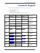
Prestige 2602R Series User’s Guide Customer Support Please have the following information ready when you contact customer support. • • • • Product model and serial number. Warranty Information. Date that you received your device. Brief description of the problem and the steps you took to solve it. METHOD SUPPORT E-MAIL TELEPHONEA WEB SITE LOCATION SALES E-MAIL FAX FTP SITE support@zyxel.com.tw +886-3-578-3942 WORLDWIDE NORTH AMERICA GERMANY DENMARK NORWAY SWEDEN FINLAND a. www.zyxel.
Prestige 2602R Series User’s Guide 7 Customer Support
Prestige 2602R Series User’s Guide Table of Contents Copyright .................................................................................................................. 2 Federal Communications Commission (FCC) Interference Statement ............... 3 Safety Warnings ....................................................................................................... 4 ZyXEL Limited Warranty..........................................................................................
Prestige 2602R Series User’s Guide Chapter 3 Password Setup ..................................................................................................... 48 3.1 Password Overview ...........................................................................................48 3.1.1 Configuring Password ...............................................................................48 Chapter 4 LAN Setup.....................................................................................................
Prestige 2602R Series User’s Guide 5.4 Traffic Shaping ...................................................................................................63 5.5 Zero Configuration Internet Access ....................................................................64 5.6 Configuring WAN Setup .....................................................................................64 5.7 Traffic Redirect ...................................................................................................70 5.
Prestige 2602R Series User’s Guide 7.6 PSTN Call Setup Signaling ................................................................................91 Chapter 8 Voice Screens ......................................................................................................... 92 8.1 Voice Screens Introduction ................................................................................92 8.2 SIP Settings Configuration .................................................................................
Prestige 2602R Series User’s Guide 11.4 Web ................................................................................................................112 11.5 Configuring Remote Management .................................................................112 Chapter 12 Universal Plug-and-Play (UPnP) ......................................................................... 114 12.1 Introducing Universal Plug and Play ..............................................................114 12.1.
Prestige 2602R Series User’s Guide Chapter 18 Introducing the SMT ............................................................................................ 144 18.1 Introduction to the SMT ..................................................................................144 18.1.1 Procedure for SMT Configuration via Telnet .........................................144 18.1.2 Entering Password ................................................................................144 18.1.
Prestige 2602R Series User’s Guide 23.2.2 Encapsulation and Multiplexing Scenarios ...........................................167 23.2.2.1 Scenario 1: One VC, Multiple Protocols ......................................167 23.2.2.2 Scenario 2: One VC, One Protocol (IP) ......................................167 23.2.2.3 Scenario 3: Multiple VCs .............................................................167 23.2.3 Outgoing Authentication Protocol .........................................................169 23.
Prestige 2602R Series User’s Guide Chapter 27 Filter Configuration .............................................................................................. 200 27.1 About Filtering ................................................................................................200 27.1.1 The Filter Structure of the Prestige .......................................................201 27.2 Configuring a Filter Set for the Prestige .........................................................202 27.
Prestige 2602R Series User’s Guide 30.2.5 TFTP and FTP over WAN Management Limitations .............................231 30.2.6 Backup Configuration Using TFTP .......................................................232 30.2.7 TFTP Command Example ....................................................................232 30.2.8 GUI-based TFTP Clients ......................................................................232 30.2.9 Backup Via Console Port ...........................................................
Prestige 2602R Series User’s Guide 33.3 Routing Policy ................................................................................................254 33.4 IP Routing Policy Setup .................................................................................255 33.5 Applying an IP Policy .....................................................................................258 33.5.1 Ethernet IP Policies ..............................................................................258 33.
Prestige 2602R Series User’s Guide IP Addressing......................................................................................................... 292 IP Classes .............................................................................................................. 292 Subnet Masks ........................................................................................................ 293 Subnetting ...............................................................................................
Prestige 2602R Series User’s Guide 19 Table of Contents
Prestige 2602R Series User’s Guide List of Figures Figure 1 Prestige Internet Access Application .................................................................... 40 Figure 2 Internet Telephone Service Provider Application .................................................. 41 Figure 3 IP-PBX Application ............................................................................................... 42 Figure 4 Prestige LAN-to-LAN Application ...............................................................
Prestige 2602R Series User’s Guide Figure 39 Time and Date ..................................................................................................... 107 Figure 40 Telnet Configuration on a TCP/IP Network ......................................................... 111 Figure 41 Remote Management ......................................................................................... 112 Figure 42 Configuring UPnP .....................................................................................
Prestige 2602R Series User’s Guide Figure 82 IP Alias Network Example ................................................................................... 161 Figure 83 Menu 3.2 TCP/IP and DHCP Setup ................................................................... 161 Figure 84 Menu 3.2.1 IP Alias Setup .................................................................................. 162 Figure 85 Menu 1 General Setup .......................................................................................
Prestige 2602R Series User’s Guide Figure 125 Example 4: Menu 15.1.1 Address Mapping Rules ............................................ 198 Figure 126 Outgoing Packet Filtering Process .................................................................... 200 Figure 127 Filter Rule Process ............................................................................................ 201 Figure 128 Menu 21 Filter Set Configuration ......................................................................
Prestige 2602R Series User’s Guide Figure 168 Menu 24.7.1 As Seen Using the Console Port ................................................. 240 Figure 169 Example Xmodem Upload ................................................................................ 241 Figure 170 Menu 24.7.2 As Seen Using the Console Port ................................................ 241 Figure 171 Example Xmodem Upload ................................................................................
Prestige 2602R Series User’s Guide Figure 211 Macintosh OS X: Apple Menu ........................................................................... 290 Figure 212 Macintosh OS X: Network ................................................................................. 290 Figure 213 Single-Computer per Router Hardware Configuration ...................................... 301 Figure 214 Prestige as a PPPoE Client ..............................................................................
Prestige 2602R Series User’s Guide List of Tables Table 1 ADSL Standards .................................................................................................... 34 Table 2 Password ............................................................................................................... 48 Table 3 LAN Setup ............................................................................................................. 57 Table 4 LAN: Static DHCP ..............................................
Prestige 2602R Series User’s Guide Table 39 Menu 1 General Setup ........................................................................................ 151 Table 40 Menu 1.1 Configure Dynamic DNS ..................................................................... 152 Table 41 Menu 2 WAN Backup Setup ................................................................................ 154 Table 42 Menu 2.1Traffic Redirect Setup ...........................................................................
Prestige 2602R Series User’s Guide Table 82 Troubleshooting Voice Calls ................................................................................ 269 Table 83 Prestige 2602R Series Power Adaptor Specifications ......................................... 279 Table 84 Classes of IP Addresses ..................................................................................... 292 Table 85 Allowed IP Address Range By Class ...................................................................
Prestige 2602R Series User’s Guide 29 List of Tables
Prestige 2602R Series User’s Guide Preface Congratulations on your purchase of the Prestige 2602R Series ADSL VoIP IAD. Models in the series ending in “1”, for example Prestige 2602R-61, denote a device that works over the analog telephone system, POTS (Plain Old Telephone Service). Models ending in “3” denote a device that works over ISDN (Integrated Services Digital Network). Models ending in “7” denote a device that works over T-ISDN (UR-2). Note: Only use firmware for your Prestige’s specific model.
Prestige 2602R Series User’s Guide Syntax Conventions • “Enter” means for you to type one or more characters. “Select” or “Choose” means for you to use one predefined choices. • The SMT menu titles and labels are in Bold Times New Roman font. Predefined field choices are in Bold Arial font. Command and arrow keys are enclosed in square brackets. [ENTER] means the Enter, or carriage return key; [ESC] means the Escape key and [SPACE BAR] means the Space Bar.
Prestige 2602R Series User’s Guide Introduction to DSL DSL (Digital Subscriber Line) technology enhances the data capacity of the existing twistedpair wire that runs between the local telephone company switching offices and most homes and offices.
Prestige 2602R Series User’s Guide 33 Introduction to DSL
Prestige 2602R Series User’s Guide CHAPTER 1 Getting To Know Your Prestige This chapter describes the key features and applications of your Prestige. 1.1 Introducing the Prestige The Prestige P2602R ADSL VoIP IAD (Integrated Access Device) combines high-speed ADSL Internet access and Voice over IP (VoIP) communication capabilities. It is ideal for small networks. VoIP is the sending of voice signals over the Internet. The Prestige lets you use a traditional analog telephone for VoIP calls.
Prestige 2602R Series User’s Guide 1.2 Features of the Prestige The following sections describe the features of the Prestige. REN A Ringer Equivalence Number is used to determine the number of devices that may be connected to the telephone line. The Prestige can support three devices per telephone port. Dynamic Jitter Buffer The Prestige has a built-in adaptive, buffer that helps to smooth out the variations in delay (jitter) for voice traffic. This helps ensure good voice quality for your conversations.
Prestige 2602R Series User’s Guide Echo Cancellation The Prestige supports G.168, an ITU-T standard for eliminating the echo caused by the sound of your voice reverberating in the telephone receiver while you talk. QoS (Quality of Service) Quality of Service (QoS) mechanisms help to provide better service on a per-flow basis. The Prestige supports Type of Service (ToS) and Differentiated Services (DiffServ). This allows the Prestige to tag voice frames so they can be prioritized over the network.
Prestige 2602R Series User’s Guide Universal Plug and Play (UPnP) Using the standard TCP/IP protocol, the Prestige and other UPnP enabled devices can dynamically join a network, obtain an IP address and convey its capabilities to other devices on the network. PPPoE Support (RFC2516) PPPoE (Point-to-Point Protocol over Ethernet) emulates a dial-up connection. It allows your ISP to use their existing network configuration with newer broadband technologies such as ADSL.
Prestige 2602R Series User’s Guide • Supports Multi-Mode standard (ANSI T1.413, Issue 2; G.dmt (G.992.1); G.lite (G992.2)). • TCP/IP (Transmission Control Protocol/Internet Protocol) network layer protocol. • ATM Forum UNI 3.1/4.0 PVC. • Supports up to 8 PVCs (UBR, CBR, VBR). • Multiple Protocol over AAL5 (RFC 1483). • PPP over AAL5 (RFC 2364). • PPP over Ethernet over AAL5 (RFC 2516). • RFC 1661. • PPP over PAP (RFC 1334). • PPP over CHAP (RFC 1994).
Prestige 2602R Series User’s Guide Networking Compatibility Your Prestige is compatible with the major ADSL DSLAM (Digital Subscriber Line Access Multiplexer) providers, making configuration as simple as possible for you. Multiplexing The Prestige supports VC-based and LLC-based multiplexing. Encapsulation The Prestige supports PPPoA (RFC 2364 - PPP over ATM Adaptation Layer 5), RFC 1483 encapsulation over ATM, MAC encapsulated routing (ENET encapsulation) as well as PPP over Ethernet (RFC 2516).
Prestige 2602R Series User’s Guide Packet Filters The Prestige's packet filtering functions allows added network security and management. Ease of Installation Your Prestige is designed for quick, intuitive and easy installation. Housing Your Prestige's compact and ventilated housing minimizes space requirements making it easy to position anywhere in your busy office. 1.3 Applications for the Prestige Here are some example uses for which the Prestige is well suited. 1.3.
Prestige 2602R Series User’s Guide The following figure shows a basic example of how you would make a VoIP call through an ITSP. You use your analog phone (A in the figure) and the Prestige (B) changes the call into VoIP. The Prestige then sends your call through your modem or router (C) to the Internet and the ITSP’s SIP server. The VoIP call server forwards calls to PSTN phones (F) through a trunking gateway (E) to the PSTN network.
Prestige 2602R Series User’s Guide Figure 3 IP-PBX Application 1.3.4 LAN to LAN Application You can use the Prestige to connect two geographically dispersed networks over the ADSL line. A typical LAN-to-LAN application for your Prestige is shown as follows. Figure 4 Prestige LAN-to-LAN Application 1.4 Prestige Hardware Installation and Connection Refer to the Quick Start Guide for information on hardware installation and connection and LED descriptions.
Prestige 2602R Series User’s Guide 43 Chapter 1 Getting To Know Your Prestige
Prestige 2602R Series User’s Guide CHAPTER 2 Introducing the Web Configurator This chapter describes how to access and navigate the web configurator. 2.1 Web Configurator Overview The embedded web configurator allows you to manage the Prestige from anywhere through a browser such as Microsoft Internet Explorer or Netscape Navigator. Use Internet Explorer 6.0 and later or Netscape Navigator 7.0 and later versions with JavaScript enabled.
Prestige 2602R Series User’s Guide Figure 6 Change Password at Login 7 You should now see the SITE MAP screen. Note: The Prestige automatically times out after five minutes of inactivity. Simply log back into the Prestige if this happens to you. 2.1.2 Resetting the Prestige If you forget your password or cannot access the web configurator, you will need to use the RESET button at the back of the Prestige to reload the factory-default configuration file.
Prestige 2602R Series User’s Guide Figure 7 Click the Web Configurator SITE MAP Screen icon (located in the top right corner of most screens) to view embedded help. 2.2 Wizard Setup Please see the Quick Start Guide for information on the Wizard Setup screens for Internet access and VoIP in the web configurator.
Prestige 2602R Series User’s Guide 47 Chapter 2 Introducing the Web Configurator
Prestige 2602R Series User’s Guide CHAPTER 3 Password Setup 3.1 Password Overview It is highly recommended that you change the password for accessing the Prestige. 3.1.1 Configuring Password To change your Prestige’s password (recommended), click Password in the Site Map screen. Figure 8 Password The following table describes the fields in this screen. Table 2 Password LABEL DESCRIPTION Old Password Type the default password or the existing password you use to access the system in this field.
Prestige 2602R Series User’s Guide 49 Chapter 3 Password Setup
Prestige 2602R Series User’s Guide CHAPTER 4 LAN Setup 4.1 LAN Overview A Local Area Network (LAN) is a shared communication system to which many computers are attached. A LAN is a computer network limited to the immediate area, usually the same building or floor of a building. The LAN screens can help you configure a LAN DHCP server and manage IP addresses. 4.1.1 LANs, WANs and the Prestige The actual physical connection determines whether the Prestige ports are LAN or WAN ports.
Prestige 2602R Series User’s Guide There are two ways that an ISP disseminates the DNS server addresses. The first is for an ISP to tell a customer the DNS server addresses, usually in the form of an information sheet, when s/he signs up. If your ISP gives you the DNS server addresses, enter them in the DNS Server fields in DHCP Setup, otherwise, leave them blank. Some ISP’s choose to pass the DNS servers using the DNS server extensions of PPP IPCP (IP Control Protocol) after the connection is up.
Prestige 2602R Series User’s Guide • DHCP server enabled with 32 client IP addresses starting from 192.168.1.33. These parameters should work for the majority of installations. If your ISP gives you explicit DNS server address(es), read the embedded web configurator help regarding what fields need to be configured. 4.5 IP Address and Subnet Mask Similar to the way houses on a street share a common street name, so too do computers on a LAN share one common network number.
Prestige 2602R Series User’s Guide 4.5.1.2 IP Assignment with RFC 1483 Encapsulation In this case the IP Address Assignment must be static with the same requirements for the IP Address and ENET ENCAP Gateway fields as stated above. 4.5.1.3 IP Assignment with ENET ENCAP Encapsulation In this case you can have either a static or dynamic IP. For a static IP you must fill in all the IP Address and ENET ENCAP Gateway fields as supplied by your ISP.
Prestige 2602R Series User’s Guide 4.5.2.1 IP Pool Setup The Prestige is pre-configured with a pool of IP addresses for the DHCP clients (DHCP Pool). See the product specifications in the appendices. Do not assign static IP addresses from the Prestige-assigned DHCP pool to your LAN computers. 4.5.3 RIP Setup RIP (Routing Information Protocol) allows a router to exchange routing information with other routers. The RIP Direction field controls the sending and receiving of RIP packets.
Prestige 2602R Series User’s Guide The Prestige supports both IGMP version 1 (IGMP-v1) and IGMP version 2 (IGMP-v2). At start up, the Prestige queries all directly connected networks to gather group membership. After that, the Prestige periodically updates this information. IP multicasting can be enabled/ disabled on the Prestige LAN and/or WAN interfaces in the web configurator (LAN; WAN). Select None to disable IP multicasting on these interfaces. 4.
Prestige 2602R Series User’s Guide Note: You must enable NAT/SUA to use the Any IP feature on the Prestige. 4.6.1 How Any IP Works Address Resolution Protocol (ARP) is a protocol for mapping an Internet Protocol address (IP address) to a physical machine address, also known as a Media Access Control or MAC address, on the local area network. IP routing table is defined on IP Ethernet devices (the Prestige) to decide which hop to use, to help forward data along to its specified destination.
Prestige 2602R Series User’s Guide Figure 11 LAN Setup The following table describes the fields in this screen. Table 3 LAN Setup LABEL DESCRIPTION DHCP DHCP If set to Server, your Prestige can assign IP addresses, an IP default gateway and DNS servers to Windows 95, Windows NT and other systems that support the DHCP client. If set to None, the DHCP server will be disabled.
Prestige 2602R Series User’s Guide Table 3 LAN Setup (continued) LABEL DESCRIPTION Secondary DNS Server As above. Remote DHCP Server If Relay is selected in the DHCP field above then enter the IP address of the actual remote DHCP server here. TCP/IP IP Address Enter the IP address of your Prestige in dotted decimal notation, for example, 192.168.1.1 (factory default). IP Subnet Mask Type the subnet mask assigned to you by your ISP (if given).
Prestige 2602R Series User’s Guide Figure 12 LAN: Static DHCP The following table describes the labels in this screen. Table 4 LAN: Static DHCP 59 LABEL DESCRIPTION # This is the index number of the Static IP table entry (row). MAC Address Type the MAC address (with colons) of a computer on your LAN. IP Address This field specifies the size, or count of the IP address pool. Back Click Back to return to the previous screen. Apply Click Apply to save your changes back to the Prestige.
Prestige 2602R Series User’s Guide CHAPTER 5 WAN Setup 5.1 WAN Overview A WAN (Wide Area Network) is an outside connection to another network or the Internet. 5.1.1 Encapsulation Be sure to use the encapsulation method required by your ISP. The Prestige supports the following methods. 5.1.1.1 ENET ENCAP The MAC Encapsulated Routing Link Protocol (ENET ENCAP) is only implemented with the IP network protocol.
Prestige 2602R Series User’s Guide 5.1.1.4 RFC 1483 RFC 1483 describes two methods for Multiprotocol Encapsulation over ATM Adaptation Layer 5 (AAL5). The first method allows multiplexing of multiple protocols over a single ATM virtual circuit (LLC-based multiplexing) and the second method assumes that each protocol is carried over a separate ATM virtual circuit (VC-based multiplexing). Please refer to the RFC for more detailed information. 5.1.
Prestige 2602R Series User’s Guide 5.2 Metric The metric represents the "cost of transmission". A router determines the best route for transmission by choosing a path with the lowest "cost". RIP routing uses hop count as the measurement of cost, with a minimum of "1" for directly connected networks. The number must be between "1" and "15"; a number greater than "15" means the link is down. The smaller the number, the lower the "cost". The metric sets the priority for the Prestige’s routes to the Internet.
Prestige 2602R Series User’s Guide By implementing PPPoE directly on the Prestige (rather than individual computers), the computers on the LAN do not need PPPoE software installed, since the Prestige does that part of the task. Furthermore, with NAT, all of the LANs’ computers will have access. 5.4 Traffic Shaping Traffic Shaping is an agreement between the carrier and the subscriber to regulate the average rate and fluctuations of data transmission over an ATM network.
Prestige 2602R Series User’s Guide Figure 13 Example of Traffic Shaping 5.5 Zero Configuration Internet Access Once you turn on and connect the Prestige to a telephone jack, it automatically detects the Internet connection settings (such as the VCI/VPI numbers and the encapsulation method) from the ISP and makes the necessary configuration changes.
Prestige 2602R Series User’s Guide Figure 14 WAN (RFC 1483) 65 Chapter 5 WAN Setup
Prestige 2602R Series User’s Guide Figure 15 WAN (PPPoA) Chapter 5 WAN Setup 66
Prestige 2602R Series User’s Guide Figure 16 WAN (ENET (ENCAP) 67 Chapter 5 WAN Setup
Prestige 2602R Series User’s Guide Figure 17 WAN Setup (PPPoE) The following table describes the fields in this screen. Table 5 WAN Setup LABEL DESCRIPTION Name Enter the name of your Internet Service Provider, e.g., MyISP. This information is for identification purposes only. Mode Select Routing (default) from the drop-down list box if your ISP allows multiple computers to share an Internet account. Otherwise select Bridge.
Prestige 2602R Series User’s Guide Table 5 WAN Setup (continued) LABEL DESCRIPTION Encapsulation Select the method of encapsulation used by your ISP from the drop-down list box. Choices vary depending on the mode you select in the Mode field. If you select Bridge in the Mode field, select either PPPoA or RFC 1483. If you select Routing in the Mode field, select PPPoA, RFC 1483, ENET ENCAP or PPPoE. Multiplex Select the method of multiplexing used by your ISP from the drop-down list.
Prestige 2602R Series User’s Guide Table 5 WAN Setup (continued) LABEL DESCRIPTION Connect on Demand Select Connect on Demand when you don't want the connection up all the time and specify an idle time-out in the Max Idle Timeout field. Max Idle Timeout Specify an idle time-out in the Max Idle Timeout field when you select Connect on Demand. The default setting is 0, which means the Internet session will not timeout. PPPoE Passthrough This field is available when you select PPPoE encapsulation.
Prestige 2602R Series User’s Guide Figure 18 Traffic Redirect Example The following network topology allows you to avoid triangle route security issues when the backup gateway is connected to the LAN. Use IP alias to configure the LAN into two or three logical networks with the Prestige itself as the gateway for each LAN network. Put the protected LAN in one subnet (Subnet 1 in the following figure) and the backup gateway in another subnet (Subnet 2).
Prestige 2602R Series User’s Guide Figure 20 WAN Backup The following table describes the fields in this screen. Table 6 WAN Backup LABEL DESCRIPTION Backup Type Select the method that the Prestige uses to check the DSL connection. Select DSL Link to have the Prestige check if the connection to the DSLAM is up. Select ICMP to have the Prestige periodically ping the IP addresses configured in the Check WAN IP Address fields.
Prestige 2602R Series User’s Guide Table 6 WAN Backup (continued) LABEL DESCRIPTION Timeout Type the number of seconds (3 recommended) for your Prestige to wait for a ping response from one of the IP addresses in the Check WAN IP Address field before timing out the request. The WAN connection is considered "down" after the Prestige times out the number of times specified in the Fail Tolerance field. Use a higher value in this field if your network is busy or congested.
Prestige 2602R Series User’s Guide CHAPTER 6 Network Address Translation (NAT) Screens 6.1 NAT Overview NAT (Network Address Translation - NAT, RFC 1631) is the translation of the IP address of a host in a packet, for example, the source address of an outgoing packet, used within one network to a different IP address known within another network. 6.1.
Prestige 2602R Series User’s Guide 6.1.2 What NAT Does In the simplest form, NAT changes the source IP address in a packet received from a subscriber (the inside local address) to another (the inside global address) before forwarding the packet to the WAN side. When the response comes back, NAT translates the destination address (the inside global address) back to the inside local address before forwarding it to the original inside host.
Prestige 2602R Series User’s Guide Figure 21 How NAT Works 6.1.4 NAT Application The following figure illustrates a possible NAT application, where three inside LANs (logical LANs using IP Alias) behind the Prestige can communicate with three distinct WAN networks. More examples follow at the end of this chapter. Figure 22 NAT Application With IP Alias 6.1.5 NAT Mapping Types NAT supports five types of IP/port mapping.
Prestige 2602R Series User’s Guide • One to One: In One-to-One mode, the Prestige maps one local IP address to one global IP address. • Many to One: In Many-to-One mode, the Prestige maps multiple local IP addresses to one global IP address. This is equivalent to SUA (for instance, PAT, port address translation), ZyXEL’s Single User Account feature that previous ZyXEL routers supported (the SUA Only option in today’s routers).
Prestige 2602R Series User’s Guide 6.3 SUA Server A SUA server set is a list of inside (behind NAT on the LAN) servers, for example, web or FTP, that you can make visible to the outside world even though SUA makes your whole inside network appear as a single computer to the outside world. You may enter a single port number or a range of port numbers to be forwarded, and the local IP address of the desired server.
Prestige 2602R Series User’s Guide 6.3.3 Configuring Servers Behind SUA (Example) Let's say you want to assign ports 21-25 to one FTP, Telnet and SMTP server (A in the example), port 80 to another (B in the example) and assign a default server IP address of 192.168.1.35 to a third (C in the example). You assign the LAN IP addresses and the ISP assigns the WAN IP address. The NAT network appears as a single host on the Internet. IP address assigned by ISP. Figure 23 Multiple Servers Behind NAT Example 6.
Prestige 2602R Series User’s Guide Table 10 NAT Mode (continued) LABEL DESCRIPTION Full Feature Select this radio button if you have multiple public WAN IP addresses for your Prestige. Edit Details Click this link to go to the NAT - Address Mapping Rules screen. Apply Click Apply to save your configuration. 6.
Prestige 2602R Series User’s Guide Figure 25 Edit SUA/NAT Server Set The following table describes the fields in this screen. Table 11 Edit SUA/NAT Server Set LABEL DESCRIPTION Start Port No. Enter a port number in this field. To forward only one port, enter the port number again in the End Port No. field. To forward a series of ports, enter the start port number here and the end port number in the End Port No. field. End Port No. Enter a port number in this field.
Prestige 2602R Series User’s Guide 6.6 Configuring Address Mapping Ordering your rules is important because the Prestige applies the rules in the order that you specify. When a rule matches the current packet, the Prestige takes the corresponding action and the remaining rules are ignored. If there are any empty rules before your new configured rule, your configured rule will be pushed up by that number of empty rules.
Prestige 2602R Series User’s Guide Table 12 Address Mapping Rules (continued) LABEL DESCRIPTION Type 1-1: One-to-one mode maps one local IP address to one global IP address. Note that port numbers do not change for the One-to-one NAT mapping type. M-1: Many-to-One mode maps multiple local IP addresses to one global IP address. This is equivalent to SUA (i.e., PAT, port address translation), ZyXEL's Single User Account feature that previous ZyXEL routers supported only.
Prestige 2602R Series User’s Guide Table 13 Address Mapping Rule Edit LABEL DESCRIPTION Type Choose the port mapping type from one of the following. • One-to-One: One-to-One mode maps one local IP address to one global IP address. Note that port numbers do not change for One-to-one NAT mapping type. • Many-to-One: Many-to-One mode maps multiple local IP addresses to one global IP address. This is equivalent to SUA (i.e.
Prestige 2602R Series User’s Guide 85 Chapter 6 Network Address Translation (NAT) Screens
Prestige 2602R Series User’s Guide CHAPTER 7 Introduction to VoIP This chapter provides background information on VoIP and SIP. 7.1 Introduction to VoIP VoIP is the sending of voice signals over the Internet Protocol. This allows you to make phone calls and send faxes over the Internet at a fraction of the cost of using the traditional circuitswitched telephone network. You can also use servers to run telephone service applications like PBX services and voice mail.
Prestige 2602R Series User’s Guide 7.2.1.2 SIP Service Domain A SIP service domain is the domain name that comes after the @ symbol in a SIP URI. For example, if 1122334455@VoIP-provider.com was your SIP URI, “VoIP-provider.com” is the SIP service domain. 7.2.2 SIP Call Progression The following figure displays the basic steps in the setup and tear down of a SIP call. A calls B. Table 14 SIP Call Progression A B 1. INVITE 2. Ringing 3. OK 4. ACK 5.Dialogue (voice traffic) 6. BYE 7.
Prestige 2602R Series User’s Guide 7.2.3.1 SIP User Agent A SIP user agent server can make and receive VoIP telephone calls. This means that SIP can be used for peer-to-peer communications even though it is a client-server protocol. In the following figure, either A or B can act as a SIP user agent client to initiate a call. A and B can also both act as a SIP user agent server to receive the call. Figure 28 SIP User Agent 7.2.3.
Prestige 2602R Series User’s Guide Figure 29 SIP Proxy Server 7.2.3.3 SIP Redirect Server A SIP redirect server accepts SIP requests, translates the destination address to an IP address and sends the translated IP address back to the device that sent the request. Then the client device that originally sent the request can send requests to the IP address that it received back from the redirect server. Redirect servers do not initiate SIP requests.
Prestige 2602R Series User’s Guide Figure 30 SIP Redirect Server 7.2.3.4 SIP Register Server A SIP register server maintains a database of SIP identity-to-IP address (or domain name) mapping. The register server checks your user name and password when you register. 7.2.4 RTP When you make a VoIP call using SIP, the RTP (Real time Transport Protocol) is used to handle voice data transfer. See RFC 1889 for details on RTP. 7.3 SIP ALG The Prestige 2602R is a SIP Application Layer Gateway (ALG).
Prestige 2602R Series User’s Guide 7.5 Voice Coding A codec (coder/decoder) codes analog voice signals into digital signals and decodes the digital signals back into voice signals. The Prestige supports the following codecs. 7.5.1 G.711 G.711 is a Pulse Code Modulation (PCM) waveform codec. G.711 provides very good sound quality but requires 64kbps of bandwidth. 7.5.2 G.729 G.
Prestige 2602R Series User’s Guide CHAPTER 8 Voice Screens This chapter describes how to configure advanced VoIP, QoS, phone and phone book settings. 8.1 Voice Screens Introduction This chapter covers the configuration of the VoIP screens. 8.2 SIP Settings Configuration Click Voice in the navigation panel and then SIP Settings to display the following screen. Use this screen to configure the Prestige’s SIP settings.
Prestige 2602R Series User’s Guide Table 15 SIP Settings LABEL DESCRIPTION SIP Account You can configure the Prestige to use multiple SIP accounts. Select one to configure its settings on the Prestige. Active SIP Select this check box to have the Prestige use this SIP account. Clear the check box to have the Prestige not use this SIP account. SIP Number Enter your SIP number in this field (use the number or text that comes before the @ symbol in a full SIP URI).
Prestige 2602R Series User’s Guide Figure 32 Voice Advanced Setup The following table describes the labels in this screen. Table 16 Voice Advanced Setup LABEL DESCRIPTION Advanced VoIP Settings This read-only field displays the number of the SIP account that you are configuring. The changes that you save in this page affect the Prestige’s settings with the SIP account displayed here.
Prestige 2602R Series User’s Guide Table 16 Voice Advanced Setup (continued) LABEL DESCRIPTION Min-SE When two SIP devices negotiate a SIP session, they must negotiate a common expiration time for idle SIP sessions. This field sets the shortest expiration time that the Prestige will accept. The Prestige checks the session expiration values of incoming SIP INVITE requests against the minimum session expiration value that you configure here.
Prestige 2602R Series User’s Guide 8.4.2 DiffServ DiffServ is a class of service (CoS) model that marks packets so that they receive specific perhop treatment at DiffServ-compliant network devices along the route based on the application types and traffic flow. Packets are marked with DiffServ Code Points (DSCPs) indicating the level of service desired.
Prestige 2602R Series User’s Guide Figure 34 QoS The following table describes the labels in this screen. Table 17 QoS LABEL DESCRIPTION SIP TOS Priority Type a priority for voice transmissions. The Prestige applies Type of Service priority tags with this priority to voice traffic that it transmits. Priorities 6 and 7 are reserved for network control traffic. It is recommended that you use priority 5 for SIP. RTP TOS Priority Type a priority for voice transmissions.
Prestige 2602R Series User’s Guide 8.6.1 Voice Activity Detection/Silence Suppression Voice Activity Detection (VAD) detects whether or not speech is present. This lets the Prestige reduce the bandwidth that a call uses by not transmitting “silent packets” when you are not speaking. 8.6.2 Comfort Noise Generation When using VAD, the Prestige generates and sends comfort noise when you are not speaking. Comfort noise uses the lowest possible transmission bandwidth to match the background noise.
Prestige 2602R Series User’s Guide The following table describes the labels in this screen. Table 18 Phone LABEL DESCRIPTION Phone Port Settings Use this field to select the phone port that you want to configure. Speaking Volume Use this field to set the loudness that the Prestige uses for the speech signal that it sends to the peer device. -1 is the quietest and 1 is the loudest.
Prestige 2602R Series User’s Guide 8.9 Speed Dial Configuration Click Voice in the navigation panel and then Speed Dial to display the following screen. Figure 36 Speed Dial The following table describes the labels in this screen. Table 19 Speed Dial LABEL DESCRIPTION Add New Entry Use this section of the screen to edit and save new or existing speed dial phone book entries. Speed Dial Select a speed dial key combination from the drop-down list box.
Prestige 2602R Series User’s Guide Table 19 Speed Dial (continued) LABEL DESCRIPTION Speed Dial Phone This section of the screen displays the currently saved speed dial entries. You can Book configure up to 10 entries and use them to make calls. Speed Dial This is the entry’s speed dial key combination. Press this key combination on a telephone attached to the Prestige in order to call the party named in this entry. SIP Number This is the SIP number of the party that you will call.
Prestige 2602R Series User’s Guide Figure 37 Lifeline The following table describes the labels in this screen. Table 20 Lifeline LABEL DESCRIPTION PSTN Pre-fix Number Specify the prefix number for dialing regular calls when the VoIP service is available. Relay to PSTN Use these fields to specify phone numbers to which the Prestige will always send calls through the regular phone service without the need of dialing a prefix number. These numbers must be for phones on the PSTN (not VoIP phones).
Prestige 2602R Series User’s Guide 103 Chapter 8 Voice Screens
Prestige 2602R Series User’s Guide CHAPTER 9 Dynamic DNS Setup 9.1 Dynamic DNS Dynamic DNS allows you to update your current dynamic IP address with one or many dynamic DNS services so that anyone can contact you (in NetMeeting, CU-SeeMe, etc.). You can also access your FTP server or Web site on your own computer using a domain name (for instance myhost.dhs.org, where myhost is a name of your choice) that will never change instead of using an IP address that changes each time you reconnect.
Prestige 2602R Series User’s Guide Figure 38 Dynamic DNS The following table describes the fields in this screen. Table 21 Dynamic DNS 105 LABEL DESCRIPTION Active Select this check box to use dynamic DNS. Service Provider This is the name of your Dynamic DNS service provider. Host Names Type the domain name assigned to your Prestige by your Dynamic DNS provider. E-mail Address Type your e-mail address. User Type your user name. Password Type the password assigned to you.
Prestige 2602R Series User’s Guide CHAPTER 10 Time and Date 10.1 Pre-defined NTP Time Servers List The Prestige uses the following pre-defined list of NTP time servers if you do not specify a time server or it cannot synchronize with the time server you specified. Note: The Prestige can use this pre-defined list of time servers regardless of the Time Protocol you select. When the Prestige uses the pre-defined list of NTP time servers, it randomly selects one server and tries to synchronize with it.
Prestige 2602R Series User’s Guide Figure 39 Time and Date The following table describes the fields in this screen. Table 23 Time and Date LABEL DESCRIPTION Time Server Use Protocol when Select the time service protocol that your time server sends when you turn on the Bootup Prestige. Not all time servers support all protocols, so you may have to check with your ISP/network administrator or use trial and error to find a protocol that works. The main difference between them is the format.
Prestige 2602R Series User’s Guide Table 23 Time and Date (continued) LABEL DESCRIPTION Start Date Enter the month and day that your daylight-savings time starts on if you selected Daylight Savings. End Date Enter the month and day that your daylight-savings time ends on if you selected Daylight Savings. Synchronize system clock with Time Server now. Select this option to have your Prestige use the time server (that you configured above) to set its internal system clock.
Prestige 2602R Series User’s Guide 109 Chapter 10 Time and Date
Prestige 2602R Series User’s Guide C H A P T E R 11 Remote Management Configuration 11.1 Remote Management Overview Remote management allows you to determine which services/protocols can access which Prestige interface (if any) from which computers. When you configure remote management to allow management from the WAN, you still need to configure a firewall rule to allow access. See the firewall chapters for details on configuring firewall rules.
Prestige 2602R Series User’s Guide • You have disabled that service in one of the remote management screens. • The IP address in the Secured Client IP field does not match the client IP address. If it does not match, the Prestige will disconnect the session immediately. • There is already another remote management session with an equal or higher priority running. You may only have one remote management session running at one time. • There is a firewall rule that blocks it. 11.1.
Prestige 2602R Series User’s Guide 11.4 Web You can use the Prestige’s embedded web configurator for configuration and file management. See the online help for details. 11.5 Configuring Remote Management Click Remote Management to open the following screen. Figure 41 Remote Management The following table describes the fields in this screen. Table 24 Remote Management LABEL DESCRIPTION Server Type Each of these labels denotes a service that you may use to remotely manage the Prestige.
Prestige 2602R Series User’s Guide 113 Chapter 11 Remote Management Configuration
Prestige 2602R Series User’s Guide CHAPTER 12 Universal Plug-and-Play (UPnP) 12.1 Introducing Universal Plug and Play Universal Plug and Play (UPnP) is a distributed, open networking standard that uses TCP/IP for simple peer-to-peer network connectivity between devices. A UPnP device can dynamically join a network, obtain an IP address, convey its capabilities and learn about other devices on the network. In turn, a device can leave a network smoothly and automatically when it is no longer in use. 12.1.
Prestige 2602R Series User’s Guide 12.2 UPnP and ZyXEL ZyXEL has achieved UPnP certification from the Universal Plug and Play Forum Creates UPnP™ Implementers Corp. (UIC). ZyXEL's UPnP implementation supports IGD 1.0 (Internet Gateway Device). At the time of writing ZyXEL's UPnP implementation supports Windows Messenger 4.6 and 4.7 while Windows Messenger 5.0 and Xbox are still being tested. The Prestige only sends UPnP multicasts to the LAN.
Prestige 2602R Series User’s Guide 12.3 Installing UPnP in Windows Example This section shows how to install UPnP in Windows Me and Windows XP. Installing UPnP in Windows Me Follow the steps below to install the UPnP in Windows Me. 1 Click Start and Control Panel. Double-click Add/Remove Programs. 2 Click on the Windows Setup tab and select Communication in the Components selection box. Click Details.
Prestige 2602R Series User’s Guide Figure 44 Add/Remove Programs: Windows Setup: Communication: Components 4 Click OK to go back to the Add/Remove Programs Properties window and click Next. 5 Restart the computer when prompted. Installing UPnP in Windows XP Follow the steps below to install the UPnP in Windows XP. 1 Click Start and Control Panel. 2 Double-click Network Connections. 3 In the Network Connections window, click Advanced in the main menu and select Optional Networking Components ….
Prestige 2602R Series User’s Guide Figure 46 Windows Optional Networking Components Wizard 5 In the Networking Services window, select the Universal Plug and Play check box.
Prestige 2602R Series User’s Guide Figure 47 Networking Services 6 Click OK to go back to the Windows Optional Networking Component Wizard window and click Next. 12.4 Using UPnP in Windows XP Example This section shows you how to use the UPnP feature in Windows XP. You must already have UPnP installed in Windows XP and UPnP activated on the Prestige. Make sure the computer is connected to a LAN port of the Prestige. Turn on your computer and the Prestige.
Prestige 2602R Series User’s Guide Figure 48 Network Connections 3 In the Internet Connection Properties window, click Settings to see the port mappings there were automatically created.
Prestige 2602R Series User’s Guide Figure 49 Internet Connection Properties 4 You may edit or delete the port mappings or click Add to manually add port mappings.
Prestige 2602R Series User’s Guide Figure 50 Internet Connection Properties: Advanced Settings Figure 51 Internet Connection Properties: Advanced Settings: Add 5 When the UPnP-enabled device is disconnected from your computer, all port mappings will be deleted automatically. 6 Select Show icon in notification area when connected option and click OK. An icon displays in the system tray.
Prestige 2602R Series User’s Guide Figure 52 System Tray Icon 7 Double-click on the icon to display your current Internet connection status. Figure 53 Internet Connection Status Web Configurator Easy Access With UPnP, you can access the web-based configurator on the Prestige without finding out the IP address of the Prestige first. This comes helpful if you do not know the IP address of the Prestige. Follow the steps below to access the web configurator. 1 Click Start and then Control Panel.
Prestige 2602R Series User’s Guide Figure 54 Network Connections 4 An icon with the description for each UPnP-enabled device displays under Local Network. 5 Right-click on the icon for your Prestige and select Invoke. The web configurator login screen displays.
Prestige 2602R Series User’s Guide Figure 55 Network Connections: My Network Places 6 Right-click on the icon for your Prestige and select Properties. A properties window displays with basic information about the Prestige.
Prestige 2602R Series User’s Guide CHAPTER 13 Logs Screens 13.1 Logs Overview The web configurator allows you to choose which categories of events and/or alerts to have the Prestige log and then display the logs or have the Prestige send them to an administrator (as e-mail) or to a syslog server. 13.1.1 Alerts and Logs An alert is a type of log that warrants more serious attention. They include system errors, attacks (access control) and attempted access to blocked web sites.
Prestige 2602R Series User’s Guide Figure 57 Log Settings The following table describes the fields in this screen. Table 26 Log Settings LABEL DESCRIPTION Address Info 127 Mail Server Enter the server name or the IP address of the mail server for the e-mail addresses specified below. If this field is left blank, logs and alert messages will not be sent via e-mail. Mail Subject Type a title that you want to be in the subject line of the log e-mail message that the Prestige sends.
Prestige 2602R Series User’s Guide Table 26 Log Settings (continued) LABEL DESCRIPTION Send alerts to Alerts are sent to the e-mail address specified in this field. If this field is left blank, alerts will not be sent via e-mail. UNIX Syslog Syslog logging sends a log to an external syslog server used to store logs. Active Click Active to enable syslog logging. Syslog IP Address Enter the server name or IP address of the syslog server that will log the selected categories of logs.
Prestige 2602R Series User’s Guide Figure 58 View Logs The following table describes the fields in this screen. Table 27 View Logs LABEL DESCRIPTION Display The categories that you select in the Log Settings screen (see section ) display in the drop-down list box. Select a category of logs to view; select All Logs to view logs from all of the log categories that you selected in the Log Settings page. Time This field displays the time the log was recorded.
Prestige 2602R Series User’s Guide Table 28 SMTP Error Messages (continued) -6 means RCPT TO fail -7 means DATA fail -8 means mail data send fail 13.4.1 Example E-mail Log An "End of Log" message displays for each mail in which a complete log has been sent. The following is an example of a log sent by e-mail. • • • • You may edit the subject title. The date format here is Day-Month-Year. The date format here is Month-Day-Year. The time format is Hour-Minute-Second.
Prestige 2602R Series User’s Guide 131 Chapter 13 Logs Screens
Prestige 2602R Series User’s Guide CHAPTER 14 System Status Screen Click System Status to open the following screen, where you can use to monitor your Prestige. Note that these fields are READ-ONLY and only for diagnostic purposes.
Prestige 2602R Series User’s Guide Figure 60 System Status 133 Chapter 14 System Status Screen
Prestige 2602R Series User’s Guide The following table describes the fields in this screen. Table 29 System Status LABEL DESCRIPTION System Status System Name This is the name of your Prestige. It is for identification purposes. ZyNOS Firmware Version This is the ZyNOS firmware version and the date created. ZyNOS is ZyXEL's proprietary Network Operating System design. DSL FW Version This is the DSL firmware version associated with your Prestige.
Prestige 2602R Series User’s Guide 14.0.1 System Statistics Click Show Statistics in the System Status screen to open the following screen. Read-only information here includes port status and packet specific statistics. Also provided are "system up time" and "poll interval(s)". The Poll Interval(s) field is configurable. Figure 61 System Status: Show Statistics The following table describes the fields in this screen.
Prestige 2602R Series User’s Guide Table 30 System Status: Show Statistics (continued) LABEL DESCRIPTION TxPkts This field displays the number of packets transmitted on this port. RxPkts This field displays the number of packets received on this port. Errors This field displays the number of error packets on this port. Tx B/s This field displays the number of bytes transmitted in the last second. Rx B/s This field displays the number of bytes received in the last second.
Prestige 2602R Series User’s Guide 137 Chapter 14 System Status Screen
Prestige 2602R Series User’s Guide CHAPTER 15 DHCP Table & Any IP 15.1 Introduction DHCP (Dynamic Host Configuration Protocol, RFC 2131 and RFC 2132) allows individual clients to obtain TCP/IP configuration at start-up from a server. You can configure the Prestige as a DHCP server or disable it. When configured as a server, the Prestige provides the TCP/IP configuration for the clients.
Prestige 2602R Series User’s Guide Figure 63 Any IP Table The following table describes the labels in this screen. Table 32 Any IP Table 139 LABEL DESCRIPTION # This field displays the index number. IP Address This field displays the IP address of the network device. MAC Address This field displays the MAC (Media Access Control) address of the computer with the displayed IP address. Every Ethernet device has a unique MAC address.
Prestige 2602R Series User’s Guide CHAPTER 16 Diagnostic Screens These read-only screens display information to help you identify problems with the Prestige. 16.0.1 Diagnostic General Screen Click Diagnostic and then General to open the screen shown next. Figure 64 Diagnostic: General The following table describes the fields in this screen. Table 33 Diagnostic: General LABEL DESCRIPTION TCP/IP Address Type the IP address of a computer that you want to ping in order to test a connection.
Prestige 2602R Series User’s Guide 16.0.2 Diagnostic DSL Line Screen Click Diagnostic and then DSL Line to open the screen shown next. Figure 65 Diagnostic: DSL Line The following table describes the fields in this screen. Table 34 Diagnostic: DSL Line LABEL Reset ADSL Line DESCRIPTION Click this button to reinitialize the ADSL line. The large text box above then displays the progress and results of this operation, for example: "Start to reset ADSL Loading ADSL modem F/W...
Prestige 2602R Series User’s Guide CHAPTER 17 Firmware Screen 17.1 Introduction Find firmware at www.zyxel.com in a file that (usually) uses the system model name with a "*.bin" extension, e.g., "Prestige.bin". The upload process uses HTTP (Hypertext Transfer Protocol) and may take up to two minutes. After a successful upload, the system will reboot. See Chapter 30 on page 228 in the parts that document the SMT for upgrading firmware using FTP/TFTP commands.
Prestige 2602R Series User’s Guide Table 35 Firmware Upgrade (continued) LABEL DESCRIPTION Upload Click Upload to begin the upload process. This process may take up to two minutes. Reset Click this button to clear all user-entered configuration information and return the Prestige to its factory defaults. Refer to the Resetting the Prestige section.
Prestige 2602R Series User’s Guide CHAPTER 18 Introducing the SMT 18.1 Introduction to the SMT The Prestige’s SMT (System Management Terminal) is a menu-driven interface that you can access over a telnet connection. This chapter shows you how to access the SMT menus via console port, how to navigate the SMT and how to configure SMT menus. 18.1.1 Procedure for SMT Configuration via Telnet The following procedure details how to telnet into your Prestige.
Prestige 2602R Series User’s Guide Figure 70 Getting Started SMT Menus Figure 71 Advanced Applications SMT Menus 145 Chapter 18 Introducing the SMT
Prestige 2602R Series User’s Guide Figure 72 Advanced Management SMT Menus 21 to 23 Figure 73 Advanced Management SMT Menus 24 to 26 18.2 Navigating the SMT Interface The SMT (System Management Terminal) is the interface that you use to configure your Prestige.
Prestige 2602R Series User’s Guide Several operations that you should be familiar with before you attempt to modify the configuration are listed in the table below. Table 36 Navigating the SMT Interface OPERATION KEY STROKE DESCRIPTION Move down to another menu [ENTER] To move forward to a submenu, type in the number of the desired submenu and press [ENTER]. Move up to a previous menu [ESC] Press [ESC] to move back to the previous menu.
Prestige 2602R Series User’s Guide 18.2.1 System Management Terminal Interface Summary Table 38 Main Menu Summary # MENU TITLE DESCRIPTION 1 General Setup Use this menu to set up your general information. 2 WAN Backup Setup Use this menu to setup traffic redirect and dial-back up. 3 LAN Setup Use this menu to set up your wireless LAN and LAN connection. 4 Internet Access Setup A quick and easy way to set up an Internet connection.
Prestige 2602R Series User’s Guide 5 Re-type your new system password in the Retype to confirm field for confirmation and press [ENTER]. Note: Note that as you type a password, the screen displays an “*” for each character you type.
Prestige 2602R Series User’s Guide CHAPTER 19 Menu 1 General Setup 19.1 General Setup Menu 1 — General Setup contains administrative and system-related information (shown next). The System Name field is for identification purposes. However, because some ISPs check this name you should enter your computer's "Computer Name". • In Windows 95/98 click Start, Settings, Control Panel, Network. Click the Identification tab, note the entry for the Computer name field and enter it as the Prestige System Name.
Prestige 2602R Series User’s Guide Figure 75 Menu 1 General Setup Menu 1 General Setup System Name= ? Location= Contact Person's Name= Domain Name= Edit Dynamic DNS= No Route IP= Yes Bridge= No Press ENTER to Confirm or ESC to Cancel: Fill in the required fields. Refer to the table shown next for more information about these fields. Table 39 Menu 1 General Setup FIELD DESCRIPTION System Name Choose a descriptive name for identification purposes. This name can be up to 30 alphanumeric characters long.
Prestige 2602R Series User’s Guide Figure 76 Menu 1.1 Configure Dynamic DNS Menu 1.1 - Configure Dynamic DNS Service Provider= WWW.DynDNS.ORG Active= No Host= EMAIL= USER= Password= ******** Enable Wildcard= No Press ENTER to Confirm or ESC to Cancel: Follow the instructions in the next table to configure dynamic DNS parameters. Table 40 Menu 1.1 Configure Dynamic DNS FIELD DESCRIPTION Service Provider This is the name of your dynamic DNS service provider.
Prestige 2602R Series User’s Guide 153 Chapter 19 Menu 1 General Setup
Prestige 2602R Series User’s Guide CHAPTER 20 Menu 2 WAN Backup Setup 20.1 Introduction to WAN Backup Setup This chapter explains how to configure the Prestige for traffic redirect connections. 20.2 Configuring WAN Backup in Menu 2 From the main menu, enter 2 to open menu 2. Figure 77 Menu 2 WAN Backup Setup Menu 2 - Wan Backup Setup Check Mechanism = DSL Link Check WAN IP Address1 = 0.0.0.0 Check WAN IP Address2 = 0.0.0.0 Check WAN IP Address3 = 0.0.0.
Prestige 2602R Series User’s Guide Table 41 Menu 2 WAN Backup Setup (continued) FIELD DESCRIPTION Recovery Interval(sec) When the Prestige is using a lower priority connection (usually a WAN backup connection), it periodically checks to whether or not it can use a higher priority connection. Type the number of seconds (30 recommended) for the Prestige to wait between checks. Allow more time if your destination IP address handles lots of traffic.
Prestige 2602R Series User’s Guide CHAPTER 21 Menu 3 LAN Setup 21.1 LAN Setup This section describes how to configure the Ethernet using Menu 3 — LAN Setup. From the main menu, enter 3 to display menu 3. Figure 79 Menu 3 LAN Setup Menu 3 - LAN Setup 1. LAN Port Filter Setup 2. TCP/IP and DHCP Setup Enter Menu Selection Number: 21.1.1 General Ethernet Setup This menu allows you to specify filter set(s) that you wish to apply to the Ethernet traffic.
Prestige 2602R Series User’s Guide • For bridging Ethernet setup refer to Chapter 25 on page 180. 21.3 TCP/IP Ethernet Setup and DHCP Use menu 3.2 to configure your Prestige for TCP/IP. To edit menu 3.2, enter 3 from the main menu to display Menu 3 — LAN Setup. When menu 3 appears, press 2 and press [ENTER] to display Menu 3.2 — TCP/IP and DHCP Ethernet Setup, as shown next: Figure 81 Menu 3.2 TCP/IP and DHCP Ethernet Setup Menu 3.
Prestige 2602R Series User’s Guide Table 43 DHCP Ethernet Setup (continued) FIELD DESCRIPTION Primary DNS Server Secondary DNS Server Enter the IP addresses of the DNS servers. The DNS servers are passed to the DHCP clients along with the IP address and the subnet mask. Remote DHCP Serve If Relay is selected in the DHCP field above then enter the IP address of the actual remote DHCP server here. Follow the instructions in the following table to configure TCP/IP parameters for the Ethernet port.
Prestige 2602R Series User’s Guide 159 Chapter 21 Menu 3 LAN Setup
Prestige 2602R Series User’s Guide CHAPTER 22 Internet Access 22.1 Internet Access Overview Refer to the chapters on the web configurator’s wizard, LAN and WAN screens for more background information on fields in the SMT screens covered in this chapter. 22.2 IP Policies Traditionally, routing is based on the destination address only and the router takes the shortest path to forward a packet.
Prestige 2602R Series User’s Guide Figure 82 IP Alias Network Example Use menu 3.2.1 to configure IP Alias on your Prestige. 22.4 IP Alias Setup Use menu 3.2 to configure the first network. Move the cursor to Edit IP Alias field and press [SPACEBAR] to choose Yes and press [ENTER] to configure the second and third network. Figure 83 Menu 3.2 TCP/IP and DHCP Setup Menu 3.2 - TCP/IP and DHCP Setup DHCP Setup DHCP= Server Client IP Pool Starting Address= 192.168.1.
Prestige 2602R Series User’s Guide Figure 84 Menu 3.2.1 IP Alias Setup Menu 3.2.
Prestige 2602R Series User’s Guide Figure 85 Menu 1 General Setup Menu 1 - General Setup System Name= ? Location= location Contact Person's Name= Domain Name= Edit Dynamic DNS= No Route IP= Yes Bridge= No Press ENTER to Confirm or ESC to Cancel: 22.6 Internet Access Configuration Menu 4 allows you to enter the Internet Access information in one screen. Menu 4 is actually a simplified setup for one of the remote nodes that you can access in menu 11.
Prestige 2602R Series User’s Guide . Table 46 Menu 4 Internet Access Setup FIELD DESCRIPTION ISP’s Name Enter the name of your Internet Service Provider (ISP). This information is for identification purposes only. Encapsulation Press [SPACE BAR] to select the method of encapsulation used by your ISP. Choices are PPPoE, PPPoA, RFC 1483 or ENET ENCAP. Multiplexing Press [SPACE BAR] to select the method of multiplexing used by your ISP. Choices are VC-based or LLC-based.
Prestige 2602R Series User’s Guide 165 Chapter 22 Internet Access
Prestige 2602R Series User’s Guide CHAPTER 23 Remote Node Configuration 23.1 Remote Node Setup Overview This section describes the protocol-independent parameters for a remote node. A remote node is required for placing calls to a remote gateway. A remote node represents both the remote gateway and the network behind it across a WAN connection. When you use menu 4 to set up Internet access, you are configuring one of the remote nodes. You first choose a remote node in Menu 11- Remote Node Setup.
Prestige 2602R Series User’s Guide Figure 87 Menu 11 Remote Node Setup 1. 2. 3. 4. 5. 6. 7. 8. Menu 11 - Remote Node Setup MyISP (ISP, SUA) ________ ________ ________ ________ ________ ________ ________ Enter Node # to Edit: 23.2.2 Encapsulation and Multiplexing Scenarios For Internet access you should use the encapsulation and multiplexing methods used by your ISP.
Prestige 2602R Series User’s Guide Figure 88 Menu 11.1 Remote Node Profile Menu 11.
Prestige 2602R Series User’s Guide Table 47 Menu 11.1 Remote Node Profile (continued) FIELD DESCRIPTION PAP – accept PAP (Password Authentication Protocol) only. Route This field determines the protocol used in routing. Options are IP and None. Bridge When bridging is enabled, your Prestige will forward any packet that it does not route to this remote node; otherwise, the packets are discarded. Select Yes to enable and No to disable.
Prestige 2602R Series User’s Guide 23.3 Remote Node Network Layer Options For the TCP/IP parameters, perform the following steps to edit Menu 11.3 – Remote Node Network Layer Options as shown next. 1 In menu 11.1, make sure IP is among the protocols in the Route field. 2 Move the cursor to the Edit IP/Bridge field, press [SPACE BAR] to select Yes, then press [ENTER] to display Menu 11.3 – Remote Node Network Layer Options. Figure 89 Menu 11.3 Remote Node Network Layer Options Menu 11.
Prestige 2602R Series User’s Guide Table 48 Menu 11.3 Remote Node Network Layer Options (continued) FIELD DESCRIPTION Address Mapping Set When Full Feature is selected in the NAT field, configure address mapping sets in menu 15.1. Select one of the NAT server sets (2-10) in menu 15.2 (see Chapter 26 on page 184 for details) and type that number here. When SUA Only is selected in the NAT field, the SMT uses NAT server set 1 in menu 15.2 (see Chapter 26 on page 184 for details).
Prestige 2602R Series User’s Guide Figure 90 Sample IP Addresses for a TCP/IP LAN-to-LAN Connection 23.4 Remote Node Filter Move the cursor to the Edit Filter Sets field in menu 11.1, then press [SPACE BAR] to select Yes. Press [ENTER] to display Menu 11.5 – Remote Node Filter. Use Menu 11.5 – Remote Node Filter to specify the filter set(s) to apply to the incoming and outgoing traffic between this remote node and the Prestige and also to prevent certain packets from triggering calls.
Prestige 2602R Series User’s Guide Figure 91 Menu 11.5 Remote Node Filter (RFC 1483 or ENET Encapsulation) Menu 11.5 - Remote Node Filter Input Filter Sets: protocol filters= device filters= Output Filter Sets: protocol filters= device filters= Enter here to CONFIRM or ESC to CANCEL: Figure 92 Menu 11.5 Remote Node Filter (PPPoA or PPPoE Encapsulation) Menu 11.
Prestige 2602R Series User’s Guide Figure 93 Menu 11.6 for VC-based Multiplexing Menu 11.6 - Remote Node ATM Layer Options VPI/VCI (VC-Multiplexing) VC Options for IP: VPI #= 8 VCI #= 35 ATM QoS Type= UBR Peak Cell Rate (PCR)= 0 Sustain Cell Rate (SCR)= 0 Maximum Burst Size (MBS)= 0 VC Options for Bridge: VPI #= 1 VCI #= 36 ATM QoS Type= N/A Peak Cell Rate (PCR)= N/A Sustain Cell Rate (SCR)= N/A Maximum Burst Size (MBR)= N/A Enter here to CONFIRM or ESC to CANCEL: 23.5.
Prestige 2602R Series User’s Guide Figure 95 Menu 11.1 Remote Node Profile Menu 11.
Prestige 2602R Series User’s Guide CHAPTER 24 Static Route Setup 24.1 IP Static Route Overview Static routes tell the Prestige routing information that it cannot learn automatically through other means. This can arise in cases where RIP is disabled on the LAN or a remote network is beyond the one that is directly connected to a remote node. Each remote node specifies only the network to which the gateway is directly connected and the Prestige has no knowledge of the networks beyond.
Prestige 2602R Series User’s Guide Figure 98 Menu 12 Static Route Setup Menu 12 - Static Route Setup 1. IP Static Route 3. Bridge Static Route Please enter selection: From menu 12, select 1 to open Menu 12.1 — IP Static Route Setup (shown next). Figure 99 Menu 12.1 IP Static Route Setup Menu 12.1 - IP Static Route Setup 1. ________ 2. ________ 3. ________ 4. ________ 5. ________ 6. ________ 7. ________ 8. ________ 9. ________ 10. ________ 11. ________ 12. ________ 13. ________ 14. ________ 15. ________ 16.
Prestige 2602R Series User’s Guide Table 50 Menu12.1.1 Edit IP Static Route FIELD DESCRIPTION Route # This is the index number of the static route that you chose in menu 12.1. Route Name Type a descriptive name for this route. This is for identification purpose only. Active This field allows you to activate/deactivate this static route. Destination IP Address This parameter specifies the IP network address of the final destination. Routing is always based on network number.
Prestige 2602R Series User’s Guide 179 Chapter 24 Static Route Setup
Prestige 2602R Series User’s Guide CHAPTER 25 Bridging Setup 25.1 Bridging in General Bridging bases the forwarding decision on the MAC (Media Access Control), or hardware address, while routing does it on the network layer (IP) address. Bridging allows the Prestige to transport packets of network layer protocols that it does not route, for example, SNA, from one network to another.
Prestige 2602R Series User’s Guide Figure 101 Menu 11.1 Remote Node Profile Menu 11.
Prestige 2602R Series User’s Guide 25.2.2 Bridge Static Route Setup Similar to network layer static routes, a bridging static route tells the Prestige the route to a node before a connection is established. You configure bridge static routes in menu 12.3.1 (go to menu 12, choose option 3, then choose a static route to edit) as shown next. Figure 103 Menu 12.3.1 Edit Bridge Static Route Menu 12.3.
Prestige 2602R Series User’s Guide 183 Chapter 25 Bridging Setup
Prestige 2602R Series User’s Guide CHAPTER 26 Network Address Translation (NAT) 26.1 Using NAT You must create a firewall rule in addition to setting up SUA/NAT, to allow traffic from the WAN to be forwarded through the Prestige. 26.1.1 SUA (Single User Account) Versus NAT SUA (Single User Account) is a ZyNOS implementation of a subset of NAT that supports two types of mapping, Many-to-One and Server. See Section 26.3 on page 186 or a detailed description of the NAT set for SUA.
Prestige 2602R Series User’s Guide Figure 104 Menu 4 Applying NAT for Internet Access Menu 4 - Internet Access Setup ISP's Name= MyISP Encapsulation= RFC 1483 Multiplexing= LLC-based VPI #= 8 VCI #= 35 ATM QoS Type= UBR Peak Cell Rate (PCR)= 0 Sustain Cell Rate (SCR)= 0 Maximum Burst Size (MBS)= 0 My Login= N/A My Password= N/A ENET ENCAP Gateway= N/A IP Address Assignment= Static IP Address= 0.0.0.
Prestige 2602R Series User’s Guide Table 53 Applying NAT in Menus 4 & 11.3 FIELD DESCRIPTION NAT Press [SPACE BAR] and then [ENTER] to select Full Feature if you have multiple public WAN IP addresses for your Prestige. The SMT uses the address mapping set that you configure and enter in the Address Mapping Set field (see Figure 107 on page 187). Select None to disable NAT. When you select SUA Only, the SMT uses Address Mapping Set 255 (see Figure 108 on page 187).
Prestige 2602R Series User’s Guide Figure 107 Menu 15.1 Address Mapping Sets Menu 15.1 - Address Mapping Sets 1. 2. 3. 4. 5. 6. 7. 8. 255. SUA (read only) Enter Menu Selection Number: 26.3.1.1 SUA Address Mapping Set Enter 255 to display the next screen (see also section 27.1.1). The fields in this menu cannot be changed. Figure 108 Menu 15.1.255 SUA Address Mapping Rules Set Idx --1. 2. 3. 4. 5. 6. 7. 8. 9. 10. Menu 15.1.
Prestige 2602R Series User’s Guide Table 54 SUA Address Mapping Rules (continued) FIELD DESCRIPTION Global Start IP This is the starting global IP address (IGA). If you have a dynamic IP, enter 0.0.0.0 as the Global Start IP. Global End IP This is the ending global IP address (IGA). Type These are the mapping types. Server allows us to specify multiple servers of different types behind NAT to this machine. See later for some examples.
Prestige 2602R Series User’s Guide 26.3.1.3 Ordering Your Rules Ordering your rules is important because the Prestige applies the rules in the order that you specify. When a rule matches the current packet, the Prestige takes the corresponding action and the remaining rules are ignored. If there are any empty rules before your new configured rule, your configured rule will be pushed up by that number of empty rules.
Prestige 2602R Series User’s Guide Figure 110 Menu 15.1.1.1 Editing/Configuring an Individual Rule in a Set Menu 15.1.1.1 Address Mapping Rule Type= One-to-One Local IP: Start= End = N/A Global IP: Start= End = N/A Server Mapping Set= N/A Press ENTER to Confirm or ESC to Cancel: The following table explains the fields in this menu. Table 56 Menu 15.1.1.1 Editing/Configuring an Individual Rule in a Set FIELD DESCRIPTION Type Press [SPACE BAR] and then [ENTER] to select from a total of five types.
Prestige 2602R Series User’s Guide Figure 111 Menu 15.2 NAT Server Setup Menu 15.2 - NAT Server Sets 1. Server Set 1 (Used for SUA Only) 2. Server Set 2 3. Server Set 3 4. Server Set 4 5. Server Set 5 6. Server Set 6 7. Server Set 7 8. Server Set 8 9. Server Set 9 10. Server Set 10 Enter Set Number to Edit: 3 Enter 1 to go to Menu 15.2.1 NAT Server Setup as follows. Figure 112 Menu 15.2.1 NAT Server Setup Menu 15.2 - NAT Server Setup Rule Start Port No. End Port No.
Prestige 2602R Series User’s Guide Figure 113 Multiple Servers Behind NAT Example 26.5 General NAT Examples The following are some examples of NAT configuration. 26.5.1 Example 1: Internet Access Only In the following Internet access example, you only need one rule where your ILAs (Inside Local addresses) all map to one dynamic IGA (Inside Global Address) assigned by your ISP.
Prestige 2602R Series User’s Guide Figure 115 Menu 4 Internet Access & NAT Example Menu 4 - Internet Access Setup ISP's Name= MyISP Encapsulation= RFC 1483 Multiplexing= LLC-based VPI #= 8 VCI #= 35 ATM QoS Type= UBR Peak Cell Rate (PCR)= 0 Sustain Cell Rate (SCR)= 0 Maximum Burst Size (MBS)= 0 My Login= N/A My Password= N/A ENET ENCAP Gateway= N/A IP Address Assignment= Static IP Address= 0.0.0.
Prestige 2602R Series User’s Guide Figure 117 Menu 15.2.1 Specifying an Inside Server Menu 15.2.1 - NAT Server Setup (Used for SUA Only) Rule Start Port No. End Port No. IP Address --------------------------------------------------1. Default Default 192.168.1.10 2. 0 0 0.0.0.0 3. 0 0 0.0.0.0 4. 0 0 0.0.0.0 5. 0 0 0.0.0.0 6. 0 0 0.0.0.0 7. 0 0 0.0.0.0 8. 0 0 0.0.0.0 9. 0 0 0.0.0.0 10. 0 0 0.0.0.0 11. 0 0 0.0.0.0 12. 0 0 0.0.0.0 Press ENTER to Confirm or ESC to Cancel: 26.5.
Prestige 2602R Series User’s Guide Figure 118 NAT Example 3 In this case you need to configure Address Mapping Set 1 from Menu 15.1 - Address Mapping Sets. Therefore you must choose the Full Feature option from the Network Address Translation field (in menu 4 or menu 11.3) in Figure 119 on page 195. 1 Enter 15 from the main menu. 2 Enter 1 to configure the Address Mapping Sets. 3 Enter 1 to begin configuring this new set. Enter a Set Name, choose the Edit Action and then enter 1 for the Select Rule field.
Prestige 2602R Series User’s Guide Figure 120 Example 3: Menu 15.1.1.1 Menu 15.1.1.1 Address Mapping Rule Type= One-to-One Local IP: Start= 192.168.1.10 End = N/A Global IP: Start= 10.132.50.1 End = N/A Server Mapping Set= N/A Press ENTER to Confirm or ESC to Cancel: Figure 121 Example 3: Final Menu 15.1.1 Set Idx --1. 2 3. 4. 5. 6. 7. 8. 9. 10. Menu 15.1.1 - Address Mapping Rules Name= Example3 Local Start IP Local End IP Global Start IP --------------- --------------- --------------192.168.1.10 10.
Prestige 2602R Series User’s Guide Figure 122 Example 3: Menu 15.2.1 Menu 15.2.1 - NAT Server Setup Rule Start Port No. End Port No. IP Address --------------------------------------------------1. Default Default 0.0.0.0 2. 80 80 192.168.1.21 3. 25 25 192.168.1.20 4. 0 0 0.0.0.0 5. 0 0 0.0.0.0 6. 0 0 0.0.0.0 7. 0 0 0.0.0.0 8. 0 0 0.0.0.0 9. 0 0 0.0.0.0 10. 0 0 0.0.0.0 11. 0 0 0.0.0.0 12. 0 0 0.0.0.0 Press ENTER to Confirm or ESC to Cancel: 26.5.
Prestige 2602R Series User’s Guide Figure 124 Example 4: Menu 15.1.1.1 Address Mapping Rule Menu 15.1.1.1 Address Mapping Rule Type= Many-to-Many No Overload Local IP: Start= 192.168.1.10 End = 192.168.1.12 Global IP: Start= 10.132.50.1 End = 10.132.50.3 Server Mapping Set= N/A Press ENTER to Confirm or ESC to Cancel: After you’ve configured your rule, you should be able to check the settings in menu 15.1.1 as shown next. Figure 125 Example 4: Menu 15.1.1 Address Mapping Rules Set Idx --1. 2. 3. 4. 5. 6.
Prestige 2602R Series User’s Guide 199 Chapter 26 Network Address Translation (NAT)
Prestige 2602R Series User’s Guide CHAPTER 27 Filter Configuration 27.1 About Filtering Your Prestige uses filters to decide whether or not to allow passage of a data packet and/or to make a call. There are two types of filter applications: data filtering and call filtering. Filters are subdivided into device and protocol filters, which are discussed later. Data filtering screens data to determine if the packet should be allowed to pass.
Prestige 2602R Series User’s Guide Figure 127 Filter Rule Process Start Packet intoFilter Fetch First Filter Set Filter Set Fetch Next Filter Set Fetch First Filter Rule Fetch Next Filter Rule Yes Yes Next Filter Set Available? No Next filter Rule Available? No Active? Yes Execute Filter Rule No Check Next Rule Forward Drop Drop Packet Accept Packet You can apply up to four filter sets to a particular port to block various types of packets.
Prestige 2602R Series User’s Guide 27.2 Configuring a Filter Set for the Prestige To configure a filter set, follow the steps shown next. 1 Enter 21 in the main menu to display Menu 21 – Filter Setup.
Prestige 2602R Series User’s Guide Figure 130 NetBIOS_LAN Filter Rules Summary Menu 21.3 - Filter Rules Summary # A Type Filter Rules M m n - - ---- --------------------------------------------------------------- - 1 Y IP Pr=17, SA=0.0.0.0, SP=137, DA=0.0.0.0, DP=53 N D F 2 N 3 N 4 N 5 N 6 N Enter Filter Rule Number (1-6) to Configure: Figure 131 IGMP Filter Rules Summary Menu 21.3.
Prestige 2602R Series User’s Guide Table 57 Abbreviations Used in the Filter Rules Summary Menu (continued) FIELD DESCRIPTION m Action Matched. “F” means to forward the packet immediately and skip checking the remaining rules. “D” means to drop the packet. “N“ means to check the next rule. n Action Not Matched. “F” means to forward the packet immediately and skip checking the remaining rules. “D” means to drop the packet. “N” means to check the next rule.
Prestige 2602R Series User’s Guide 27.4.1 TCP/IP Filter Rule This section shows you how to configure a TCP/IP filter rule. TCP/IP rules allow you to base the rule on the fields in the IP and the upper layer protocol, for example, UDP and TCP headers. To configure TCP/IP rules, select TCP/IP Filter Rule from the Filter Type field and press [ENTER] to open the TCP/IP Filter Rule menu, as shown next. Figure 132 TCP/IP Filter Rule Menu 21.1.
Prestige 2602R Series User’s Guide Table 59 TCP/IP Filter Rule (continued) FIELD DESCRIPTION Port # Type the destination port of the packets you want to filter. The field range is 0 to 65535. A 0 field is ignored. Port # Comp Select the comparison to apply to the destination port in the packet against the value given in Destination: Port #. Choices are None, Less, Greater, Equal or Not Equal. Source: IP Addr Type the source IP Address of the packet you want to filter. A 0.0.0.0 field is ignored.
Prestige 2602R Series User’s Guide Figure 133 Executing an IP Filter Packet into IP Filter Filter Active? No Yes Apply SrcAddrMask to Src Addr Check Src IP Addr Not Matched Matched Apply DestAddrMask to Dest Addr Check Dest IP Addr Not Matched Matched Check IP Protocol Not Matched Matched Check Src & Dest Port Not Matched Matched More? Yes No Action Matched Drop Action Not Matched Check Next Rule Check Next Rule Drop Forward Forward Drop Packet Check Next Rule Accept Packet 27.4.
Prestige 2602R Series User’s Guide To configure a generic rule select an empty filter set in menu 21, for example 5. Select Generic Filter Rule in the Filter Type field and press [ENTER] to open the Generic Filter Rule menu, as shown in the following figure. Figure 134 Generic Filter Rule Menu 21.5.
Prestige 2602R Series User’s Guide Table 60 Generic Filter Rule (continued) FIELD DESCRIPTION Action Not Matched Select the action for a packet not matching the rule. Choices are Check Next Rule, Forward or Drop. When you have completed this menu, press [ENTER] at the prompt “Press ENTER to Confirm or ESC to Cancel:” to save your configuration, or press [ESC] at any time to cancel. 27.
Prestige 2602R Series User’s Guide Figure 136 Sample Telnet Filter 1 Enter 1 in the menu 21 to display the Filter Set Configuration menu. 2 Enter the index number of the filter set you want to configure (in this case 6). 3 Type a descriptive name or comment in the Edit Comments field (for example, TELNET_WAN) and press [ENTER]. 4 Press [ENTER] at the message “Press [ENTER] to confirm or [ESC] to cancel ...” to open the Filter Rules Summary menu. 5 Type 1 to configure the first filter rule.
Prestige 2602R Series User’s Guide 2 Go to the Edit Filter Sets field, press [SPACE BAR] to choose Yes and press [ENTER]. This brings you to menu 11.5. Apply the example filter set (for example, filter set 3) in this menu as shown in the next section. This shows you that you have configured and activated (A = Y) a TCP/IP filter rule (Type = IP, Pr = 6) for destination telnet ports (DP = 23). M = N means an action can be taken immediately.
Prestige 2602R Series User’s Guide 27.7.1 Ethernet Traffic You seldom need to filter Ethernet traffic; however, the filter sets may be useful to block certain packets, reduce traffic and prevent security breaches. Go to menu 3.1 (shown next) and type the number(s) of the filter set(s) that you want to apply as appropriate. You can choose up to four filter sets (from twelve) by typing their numbers separated by commas, for example, 3, 4, 6, 11.
Prestige 2602R Series User’s Guide 27.8 System Password For information on changing the Prestige password, please see Section 18.3 on page 148.
Prestige 2602R Series User’s Guide CHAPTER 28 SNMP Configuration 28.1 About SNMP Simple Network Management Protocol (SNMP) is a protocol used for exchanging management information between network devices. SNMP is a member of the TCP/IP protocol suite. Your Prestige supports SNMP agent functionality, which allows a manager station to manage and monitor the Prestige through the network. The Prestige supports SNMP version one (SNMPv1) and version two c (SNMPv2c).
Prestige 2602R Series User’s Guide The managed devices contain object variables/managed objects that define each piece of information to be collected about a device. Examples of variables include the number of packets received, node port status etc. A Management Information Base (MIB) is a collection of managed objects. SNMP allows a manager and agents to communicate for the purpose of accessing these objects. SNMP itself is a simple request/response protocol based on the manager/agent model.
Prestige 2602R Series User’s Guide Figure 142 Menu 22 SNMP Configuration Menu 22 - SNMP Configuration SNMP: Get Community= public Set Community= public Trusted Host= 0.0.0.0 Trap: Community= public Destination= 0.0.0.0 Press ENTER to Confirm or ESC to Cancel: The following table describes the SNMP configuration parameters.
Prestige 2602R Series User’s Guide Table 63 SNMP Traps (continued) TRAP # TRAP NAME DESCRIPTION 5 authenticationFailure (defined in RFC-1215) A trap is sent to the manager when receiving any SNMP gets or sets requirements with wrong community (password). 6 whyReboot (defined in ZYXEL-MIB) A trap is sent with the reason of restart before rebooting when the system is going to restart (warm start).
Prestige 2602R Series User’s Guide CHAPTER 29 System Information and Diagnosis 29.1 Overview These tools include updates on system status, port status, log and trace capabilities and upgrades for the system software. This chapter describes how to use these tools in detail. Type 24 in the main menu to open Menu 24 – System Maintenance, as shown in the following figure. Figure 143 Menu 24 System Maintenance Menu 24 - System Maintenance 1. 2. 3. 4. 5. 6. 7. 8. 9. 10. 11.
Prestige 2602R Series User’s Guide The following table describes the fields present in Menu 24.1 — System Maintenance — Status which are read-only and meant for diagnostic purposes. Figure 144 Menu 24.1 System Maintenance : Status Menu 24.1 - System Maintenance - Status Node-Lnk Status TxPkts RxPkts Time 1-PPPoA N/A 0 0 2 N/A 0 0 3 N/A 0 0 4 N/A 0 0 5 N/A 0 0 6 N/A 0 0 7 N/A 0 0 My WAN IP (from ISP): 0.0.0.0 Ethernet: Status: Tx Pkts: 528 Collisions: 0 Rx Pkts: 505 CPU Load = 2.
Prestige 2602R Series User’s Guide Table 65 Menu 24.1 System Maintenance: Status (continued) FIELD Line Status DESCRIPTION This shows the current status of the xDSL line, which can be Up or Down. Upstream Speed This shows the upstream transfer rate in kbps. Downstream Speed This shows the downstream transfer rate in kbps. CPU Load This specifies the percentage of CPU utilization. 29.3 System Information To get to the System Information: 1 Enter 24 to display Menu 24 — System Maintenance.
Prestige 2602R Series User’s Guide Figure 146 Menu 24.2.1 System Maintenance: Information Menu 24.2.1 - System Maintenance - Information Name: Routing: IP ZyNOS F/W Version: V3.40(RE.0) | 12/3/2004 ADSL Chipset Vendor: TI AR7 01.01.00.00 Standard: Multi-Mode LAN Ethernet Address: 00:a0:c5:78:de:8d IP Address: 192.168.1.1 IP Mask: 255.255.255.0 DHCP: Server Press ESC or RETURN to Exit: The following table describes the fields in this menu. Table 66 Menu 24.2.
Prestige 2602R Series User’s Guide Figure 147 Menu 24.2.2 System Maintenance : Change Console Port Speed Menu 24.2.2 – System Maintenance – Change Console Port Speed Console Port Speed: 9600 Press ENTER to Confirm or ESC to Cancel: Once you change the Prestige console port speed, you must also set the speed parameter for the communication software you are using to connect to the Prestige. 29.4 Log and Trace There are two logging facilities in the Prestige.
Prestige 2602R Series User’s Guide Figure 149 Sample Error and Information Messages 53 Sat Jan 01 54 Sat Jan 01 55 Sat Jan 01 56 Sat Jan 01 57 Sat Jan 01 58 Sat Jan 01 59 Sat Jan 01 60 Sat Jan 01 62 Sat Jan 01 63 Sat Jan 01 Clear Error Log 00:00:03 00:00:03 00:00:03 00:00:03 00:00:03 00:03:06 00:03:06 00:23:21 00:23:38 00:23:38 (y/n): 2000 2000 2000 2000 2000 2000 2000 2000 2000 2000 PP01 -WARN PP01 INFO PP01 INFO PP20 INFO PP21 INFO PP19 INFO PP01 INFO PP01 INFO PP19 INFO PP01 INFO SNMP TRAP 0: cold st
Prestige 2602R Series User’s Guide Figure 151 Syslog Example 1 - CDR SdcmdSyslogSend ( SYSLOG_CDR, SYSLOG_INFO, String); String = board xx line xx channel xx, call xx, str board = the hardware board ID line = the WAN ID in a board Channel = channel ID within the WAN call = the call reference number which starts from 1 and increments by 1 for each new call str = C01 Outgoing Call dev xx ch xx (dev:device No. ch:channel No.
Prestige 2602R Series User’s Guide Figure 151 Syslog Example (continued) prot: Protocol (“TCP”, ”UDP”, ”ICMP”) spo: Source port dpo: Destination port Jul 19 14:43:55 192.168.102.2 ZYXEL: IP [Src=202.132.154.123 Dst=255.255.255.255 UDP spo=0208 dpo=0208]} S03>R01mF Jul 19 14:44:00 192.168.102.2 ZYXEL: IP [Src=192.168.102.20 Dst=202.132.154.1 UDP spo=05d4 dpo=0035]} S03>R01mF Jul 19 14:44:04 192.168.102.2 ZYXEL: IP [Src=192.168.102.20 Dst=202.132.154.
Prestige 2602R Series User’s Guide The following table describes the diagnostic tests available in menu 24.4 for and the connections. Table 68 Menu 24.4 System Maintenance Menu: Diagnostic FIELD DESCRIPTION Reset xDSL Re-initialize the xDSL link to the telephone company. Ping Host Ping the host to see if the links and TCP/IP protocol on both systems are working. Reboot System Reboot the Prestige. Command Mode Type the mode to test and diagnose your Prestige using specified commands.
Prestige 2602R Series User’s Guide 227 Chapter 29 System Information and Diagnosis
Prestige 2602R Series User’s Guide CHAPTER 30 Firmware and Configuration File Maintenance 30.1 Filename Conventions The configuration file (often called the romfile or rom-0) contains the factory default settings in the menus such as password, DHCP Setup, TCP/IP Setup, etc. It arrives from ZyXEL with a “rom” filename extension. Once you have customized the Prestige's settings, they can be saved back to your computer under a filename of your choosing.
Prestige 2602R Series User’s Guide The following table is a summary. Please note that the internal filename refers to the filename on the Prestige and the external filename refers to the filename not on the Prestige, that is, on your computer, local network or FTP site and so the name (but not the extension) may vary. After uploading new firmware, see the ZyNOS F/W Version field in Menu 24.2.1 – System Maintenance – Information to confirm that you have uploaded the correct firmware version.
Prestige 2602R Series User’s Guide Figure 153 Telnet in Menu 24.5 Menu 24.5 - System Maintenance - Backup Configuration To transfer the configuration file to your workstation, follow the procedure below: 1. Launch the FTP client on your workstation. 2. Type "open" and the IP address of your Prestige. Then type "root" and SMT password as requested. 3. Locate the 'rom-0' file. 4. Type 'get rom-0' to back up the current Prestige configuration to your workstation.
Prestige 2602R Series User’s Guide Figure 154 FTP Session Example 331 Enter PASS command Password: 230 Logged in ftp> bin 200 Type I OK ftp> get rom-0 zyxel.rom 200 Port command okay 150 Opening data connection for STOR ras 226 File received OK ftp: 16384 bytes sent in 1.10Seconds 297.89Kbytes/sec. ftp> quit 30.2.4 GUI-based FTP Clients The following table describes some of the commands that you may see in GUI-based FTP clients.
Prestige 2602R Series User’s Guide 30.2.6 Backup Configuration Using TFTP The Prestige supports the up/downloading of the firmware and the configuration file using TFTP (Trivial File Transfer Protocol) over LAN. Although TFTP should work over WAN as well, it is not recommended. To use TFTP, your computer must have both telnet and TFTP clients. To backup the configuration file, follow the procedure shown next. 1 Use telnet from your computer to connect to the Prestige and log in.
Prestige 2602R Series User’s Guide Table 71 General Commands for GUI-based TFTP Clients COMMAND DESCRIPTION Host Enter the IP address of the Prestige. 192.168.1.1 is the Prestige’s default IP address when shipped. Send/Fetch Use “Send” to upload the file to the Prestige and “Fetch” to back up the file on your computer. Local File Enter the path and name of the firmware file (*.bin extension) or configuration file (*.rom extension) on your computer. Remote File This is the filename on the Prestige.
Prestige 2602R Series User’s Guide Figure 157 Backup Configuration Example Type a location for storing the configuration file or click Browse to look for one. Choose the Xmodem protocol. Then click Receive. 4 After a successful backup you will see the following screen. Press any key to return to the SMT menu. Figure 158 Successful Backup Confirmation Screen ** Backup Configuration completed. OK. ### Hit any key to continue.### 30.
Prestige 2602R Series User’s Guide Figure 159 Telnet into Menu 24.6 Menu 24.6 -- System Maintenance - Restore Configuration To transfer the firmware and configuration file to your workstation, follow the procedure below: 1. Launch the FTP client on your workstation. 2. Type "open" and the IP address of your Prestige. Then type "root" and SMT password as requested. 3.
Prestige 2602R Series User’s Guide 30.3.3 Restore Via Console Port Note: The console port is internal and reserved for technician use only. Restore configuration via console port by following the HyperTerminal procedure shown next. Procedures using other serial communications programs should be similar. 1 Display menu 24.6 and enter “y” at the following screen. Figure 161 System Maintenance: Restore Configuration Ready to restore Configuration via Xmodem.
Prestige 2602R Series User’s Guide Figure 164 Successful Restoration Confirmation Screen Save to ROM Hit any key to start system reboot. 30.4 Uploading Firmware and Configuration Files This section shows you how to upload firmware and configuration files. You can upload configuration files by following the procedure in Section 30.2 on page 229or by following the instructions in Menu 24.7.2 – System Maintenance – Upload System Configuration File.
Prestige 2602R Series User’s Guide Figure 166 Telnet Into Menu 24.7.2 System Maintenance Menu 24.7.2 - System Maintenance - Upload System Configuration File To upload the system configuration file, follow the procedure below: 1. Launch the FTP client on your workstation. 2. Type "open" and the IP address of your system. Then type "root" and SMT password as requested. 3.
Prestige 2602R Series User’s Guide 30.4.4 FTP Session Example of Firmware File Upload Figure 167 FTP Session Example of Firmware File Upload 331 Enter PASS command Password: 230 Logged in ftp> bin 200 Type I OK ftp> put firmware.bin ras 200 Port command okay 150 Opening data connection for STOR ras 226 File received OK ftp: 1103936 bytes sent in 1.10Seconds 297.89Kbytes/sec. ftp> quit More commands (found in GUI-based FTP clients) are listed earlier in this chapter. Refer to Section 30.2.
Prestige 2602R Series User’s Guide 30.4.6 TFTP Upload Command Example The following is an example TFTP command: tftp [-i] host put firmware.bin ras where “i” specifies binary image transfer mode (use this mode when transferring binary files), “host” is the Prestige’s IP address and “put” transfers the file source on the computer (firmware.bin – name of the firmware on the computer) to the file destination on the remote host (ras - name of the firmware on the Prestige).
Prestige 2602R Series User’s Guide 30.4.7.2 Example Xmodem Firmware Upload Using HyperTerminal Click Transfer, then Send File to display the following screen. Figure 169 Example Xmodem Upload After the firmware upload process has completed, the Prestige will automatically restart. 30.4.7.3 Uploading Configuration File Via Console Port 1 Select 2 from Menu 24.7 – System Maintenance – Upload Firmware to display Menu 24.7.2 - System Maintenance - Upload System Configuration File.
Prestige 2602R Series User’s Guide 3 Enter “atgo” to restart the Prestige. 30.4.7.4 Example Xmodem Configuration Upload Using HyperTerminal Click Transfer, then Send File to display the following screen. Figure 171 Example Xmodem Upload After the configuration upload process has completed, restart the Prestige by entering “atgo”.
Prestige 2602R Series User’s Guide 243 Chapter 30 Firmware and Configuration File Maintenance
Prestige 2602R Series User’s Guide CHAPTER 31 System Maintenance 31.1 Command Interpreter Mode The Command Interpreter (CI) is a part of the main system firmware. The CI provides much of the same functionality as the SMT, while adding some low-level setup and diagnostic functions. Enter the CI from the SMT by selecting menu 24.8. See the included disk or the zyxel.com web site for more detailed information on CI commands. Enter 8 from Menu 24 — System Maintenance.
Prestige 2602R Series User’s Guide 31.2 Call Control Support Call Control Support is only applicable when Encapsulation is set to PPPoE in menu 4 or menu 11.1. The budget management function allows you to set a limit on the total outgoing call time of the Prestige within certain times. When the total outgoing call time exceeds the limit, the current call will be dropped and any future outgoing calls will be blocked. To access the call control menu, select option 9 in menu 24 to go to Menu 24.
Prestige 2602R Series User’s Guide The total budget is the time limit on the accumulated time for outgoing calls to a remote node. When this limit is reached, the call will be dropped and further outgoing calls to that remote node will be blocked. After each period, the total budget is reset. The default for the total budget is 0 minutes and the period is 0 hours, meaning no budget control. You can reset the accumulated connection time in this menu by entering the index of a remote node.
Prestige 2602R Series User’s Guide Figure 177 Menu 24.10 System Maintenance: Time and Date Setting Menu 24.10 - System Maintenance - Time and Date Setting Use Time Server when Bootup= None Time Server Address= N/A Current Time: 00 : 51 : 24 New Time (hh:mm:ss): 00 : 51 : 19 Current Date: 2000 - 01 - 01 New Date (yyyy-mm-dd): 2000 - 01 - 01 Time Zone= GMT Daylight Saving= No Start Date (mm-dd): 01 - 00 End Date (mm-dd): 01 - 00 Press ENTER to Confirm or ESC to Cancel: Table 73 Menu 24.
Prestige 2602R Series User’s Guide • 24-hour intervals after starting.
Prestige 2602R Series User’s Guide 249 Chapter 31 System Maintenance
Prestige 2602R Series User’s Guide CHAPTER 32 Remote Management 32.1 Remote Management Overview Remote management allows you to determine which services/protocols can access which Prestige interface (if any) from which computers. When you configure remote management to allow management from the WAN, you still need to configure a firewall rule to allow access. See the firewall chapters for details on configuring firewall rules. 32.
Prestige 2602R Series User’s Guide Figure 178 Menu 24.11 Remote Management Control Menu 24.11 - Remote Management Control TELNET Server: Server Port = 23 Secured Client IP = 0.0.0.0 FTP Server: Server Port = 21 Secured Client IP = 0.0.0.0 Web Server: Server Port = 80 Secured Client IP = 0.0.0.0 Server Access = LAN only Server Access = LAN only Server Access = LAN only Press ENTER to Confirm or ESC to Cancel: The following table describes the fields in this menu. Table 74 Menu 24.
Prestige 2602R Series User’s Guide 32.3 Remote Management and NAT When NAT is enabled: • Use the Prestige’s WAN IP address when configuring from the WAN. • Use the Prestige’s LAN IP address when configuring from the LAN. 32.4 System Timeout There is a default system management idle timeout of five minutes (three hundred seconds). The Prestige automatically logs you out if the management session remains idle for longer than this timeout period.
Prestige 2602R Series User’s Guide 253 Chapter 32 Remote Management
Prestige 2602R Series User’s Guide CHAPTER 33 IP Policy Routing 33.1 IP Policy Routing Overview Traditionally, routing is based on the destination address only and the IAD takes the shortest path to forward a packet. IP Routing Policy (IPPR) provides a mechanism to override the default routing behavior and alter the packet forwarding based on the policy defined by the network administrator. Policy-based routing is applied to incoming packets on a per interface basis, prior to the normal routing. 33.
Prestige 2602R Series User’s Guide IPPR follows the existing packet filtering facility of RAS in style and in implementation. The policies are divided into sets, where related policies are grouped together. A user defines the policies before applying them to an interface or a remote node, in the same fashion as the filters. There are 12 policy sets with six policies in each set. 33.4 IP Routing Policy Setup Menu 25 shows all the policies defined.
Prestige 2602R Series User’s Guide Figure 180 Menu 25.1 IP Routing Policy Setup Menu 25.1 - IP Routing Policy Setup # A Criteria/Action - - -------------------------------------------------------------------------1 Y SA=1.1.1.1-1.1.1.1,DA=2.2.2.2-2.2.2.5 SP=20-25,DP=20-25,P=6,T=NM,PR=0 |GW=192.168.1.
Prestige 2602R Series User’s Guide Figure 181 Menu 25.1.1 IP Routing Policy Menu 25.1.1 - IP Routing Policy Policy Set Name= test Active= No Criteria: IP Protocol = 0 Type of Service= Don't Care Precedence = Don't Care Source: addr start= 0.0.0.0 port start= N/A Destination: addr start= 0.0.0.0 port start= N/A Action= Matched Gateway addr = 0.0.0.
Prestige 2602R Series User’s Guide Table 76 Menu 25.1.1 IP Routing Policy (continued) FIELD DESCRIPTION Gateway addr Defines the outgoing gateway address. The gateway must be on the same subnet as the Prestige if it is on the LAN, otherwise, the gateway must be the IP address of a remote node. The default gateway is specified as 0.0.0.0. Type of Service Set the new TOS value of the outgoing packet.
Prestige 2602R Series User’s Guide Figure 182 Menu 3.2 TCP/IP and DHCP Ethernet Setup Menu 3.2 - TCP/IP and DHCP Setup DHCP Setup DHCP= Server Client IP Pool Starting Address= 192.168.1.33 Size of Client IP Pool= 32 Primary DNS Server= 0.0.0.0 Secondary DNS Server= 0.0.0.0 Remote DHCP Server= N/A TCP/IP Setup: IP Address= 192.168.1.1 IP Subnet Mask= 255.255.255.0 RIP Direction= Both Version= RIP-1 Multicast= None IP Policies= Edit IP Alias= No Press ENTER to Confirm or ESC to Cancel: Go to menu 11.
Prestige 2602R Series User’s Guide Figure 184 Example of IP Policy Routing To force packets coming from clients with IP addresses of 192.168.1.33 to 192.168.1.64 to be routed to the Internet via the WAN port of the Prestige, follow the steps as shown next. 1 Create a routing policy set in menu 25. 2 Create a rule for this set in Menu 25.1.1 — IP Routing Policy as shown next. Figure 185 IP Routing Policy Example Menu 25.1.
Prestige 2602R Series User’s Guide 3 Create a rule in menu 25.1 for this set to route packets from any host (IP=0.0.0.0 means any host) with protocol TCP and port FTP access through another gateway (192.168.1.100). Figure 186 IP Routing Policy Example Menu 25.1.1 - IP Routing Policy Policy Set Name= set2 Active= Yes Criteria: IP Protocol = 6 Type of Service= Don't Care Precedence = Don't Care Source: addr start= 0.0.0.0 port start= 0 Destination: addr start= 0.0.0.
Prestige 2602R Series User’s Guide CHAPTER 34 Call Scheduling 34.1 Introduction The call scheduling feature allows the Prestige to manage a remote node and dictate when a remote node should be called and for how long. This feature is similar to the scheduler in a videocassette recorder (you can specify a time period for the VCR to record). You can apply up to 4 schedule sets in Menu 11.1 — Remote Node Profile. From the main menu, enter 26 to access Menu 26 — Schedule Setup as shown next.
Prestige 2602R Series User’s Guide Figure 189 Menu 26.1 Schedule Set Setup Menu 26.1 Schedule Set Setup Active= Yes Start Date(yyyy-mm-dd)= 2000 - 01 - 01 How Often= Once Once: Date(yyyy-mm-dd)= 2000 - 01 - 01 Weekdays: Sunday= N/A Monday= N/A Tuesday= N/A Wednesday= N/A Thursday= N/A Friday= N/A Saturday= N/A Start Time(hh:mm)= 00 : 00 Duration(hh:mm)= 00 : 00 Action= Forced On Press ENTER to Confirm or ESC to Cancel: If a connection has been already established, your Prestige will not drop it.
Prestige 2602R Series User’s Guide Table 77 Menu 26.1 Schedule Set Setup (continued) FIELD DESCRIPTION Action Forced On means that the connection is maintained whether or not there is a demand call on the line and will persist for the time period specified in the Duration field. Forced Down means that the connection is blocked whether or not there is a demand call on the line. Enable Dial-On-Demand means that this schedule permits a demand call on the line.
Prestige 2602R Series User’s Guide 265 Chapter 34 Call Scheduling
Prestige 2602R Series User’s Guide CHAPTER 35 Troubleshooting This chapter covers potential problems and the corresponding remedies. 35.1 Problems Starting Up the Prestige Table 78 Troubleshooting Starting Up Your Prestige PROBLEM CORRECTIVE ACTION None of the LEDs turn on when I turn on the Prestige. Make sure that the Prestige’s power adaptor is connected to the Prestige and plugged in to an appropriate power source. Check that the Prestige and the power source are both turned on.
Prestige 2602R Series User’s Guide 35.3 Problems with the WAN Table 80 Troubleshooting the WAN PROBLEM CORRECTIVE ACTION The DSL LED is off. Check the telephone wire and connections between the Prestige DSL port and the wall jack. Make sure that the telephone company has checked your phone line and set it up for DSL service. Reset your ADSL line to reinitialize your link to the DSLAM. I cannot get a WAN IP address from the ISP. 267 The ISP provides the WAN IP address after authenticating you.
Prestige 2602R Series User’s Guide 35.4 Problems Accessing the Prestige Table 81 Troubleshooting Accessing the Prestige PROBLEM CORRECTIVE ACTION I cannot access the Prestige. The username is “admin”. The default password is “1234”. The Password and Username fields are case-sensitive. Make sure that you enter the correct password and username using the proper casing. If you have changed the password and have now forgotten it, you will need to upload the default configuration file (Refer to Section 2.1.
Prestige 2602R Series User’s Guide 35.5 Problems Making Voice Calls Table 82 Troubleshooting Voice Calls PROBLEM CORRECTIVE ACTION There is no dial tone. Check the telephone connections. You can test the telephone wire by using it to connect a telephone directly to a telephone outlet and checking for a dial tone. If there is still no dial tone, then try a different telephone wire or telephone. I can’t make calls. The VoIP LED does not turn orange if your Internet and/or SIP settings are incorrect .
Prestige 2602R Series User’s Guide Figure 191 Pop-up Blocker You can also check if pop-up blocking is disabled in the Pop-up Blocker section in the Privacy tab. 1 In Internet Explorer, select Tools, Internet Options, Privacy. 2 Clear the Block pop-ups check box in the Pop-up Blocker section of the screen. This disables any web pop-up blockers you may have enabled. Figure 192 Internet Options 3 Click Apply to save this setting. 35.6.1.
Prestige 2602R Series User’s Guide Figure 193 Internet Options 3 Type the IP address of your device (the web page that you do not want to have blocked) with the prefix “http://”. For example, http://192.168.1.1. 4 Click Add to move the IP address to the list of Allowed sites.
Prestige 2602R Series User’s Guide Figure 194 Pop-up Blocker Settings 5 Click Close to return to the Privacy screen. 6 Click Apply to save this setting. 35.6.2 JavaScripts If pages of the web configurator do not display properly in Internet Explorer, check that JavaScripts are allowed. 1 In Internet Explorer, click Tools, Internet Options and then the Security tab.
Prestige 2602R Series User’s Guide Figure 195 Internet Options 2 Click the Custom Level... button. 3 Scroll down to Scripting. 4 Under Active scripting make sure that Enable is selected (the default). 5 Under Scripting of Java applets make sure that Enable is selected (the default). 6 Click OK to close the window.
Prestige 2602R Series User’s Guide Figure 196 Security Settings - Java Scripting 35.6.3 Java Permissions 1 From Internet Explorer, click Tools, Internet Options and then the Security tab. 2 Click the Custom Level... button. 3 Scroll down to Microsoft VM. 4 Under Java permissions make sure that a safety level is selected. 5 Click OK to close the window.
Prestige 2602R Series User’s Guide Figure 197 Security Settings - Java 35.6.3.0.1 JAVA (Sun) 1 From Internet Explorer, click Tools, Internet Options and then the Advanced tab. 2 make sure that Use Java 2 for
Prestige 2602R Series User’s Guide Figure 198 Java (Sun) Chapter 35 Troubleshooting 276
Prestige 2602R Series User’s Guide 277 Chapter 35 Troubleshooting
Prestige 2602R Series User’s Guide APPENDIX A Hardware Specifications Ethernet Cable Pin Assignments Figure 199 Ethernet Cable Pin Assignments Appendix A Hardware Specifications 278
Prestige 2602R Series User’s Guide Prestige 2602R Series Power Adaptor Specifications Table 83 Prestige 2602R Series Power Adaptor Specifications NORTH AMERICAN PLUG STANDARDS AC Power Adapter Model 30-112-122204 Input Power 120VAC/60Hz Output Power 12V AC, 1A Power Consumption 12W Safety Standards UL,CUL(UL 1950) EUROPEAN PLUG STANDARDS AC Power Adapter Model ADS6818-1818-B 1810 Input Power AC 100~240Volts/50/60Hz/0.
Prestige 2602R Series User’s Guide APPENDIX B Setting up Your Computer’s IP Address All computers must have a 10M or 100M Ethernet adapter card and TCP/IP installed. Windows 95/98/Me/NT/2000/XP, Macintosh OS 7 and later operating systems and all versions of UNIX/LINUX include the software components you need to install and use TCP/ IP on your computer. Windows 3.1 requires the purchase of a third-party TCP/IP application package.
Prestige 2602R Series User’s Guide Figure 200 WIndows 95/98/Me: Network: Configuration Installing Components The Network window Configuration tab displays a list of installed components. You need a network adapter, the TCP/IP protocol and Client for Microsoft Networks. If you need the adapter: 1 In the Network window, click Add. 2 Select Adapter and then click Add. 3 Select the manufacturer and model of your network adapter and then click OK. If you need TCP/IP: 1 In the Network window, click Add.
Prestige 2602R Series User’s Guide 3 Select Microsoft from the list of manufacturers. 4 Select Client for Microsoft Networks from the list of network clients and then click OK. 5 Restart your computer so the changes you made take effect. Configuring 1 In the Network window Configuration tab, select your network adapter's TCP/IP entry and click Properties 2 Click the IP Address tab. • • If your IP address is dynamic, select Obtain an IP address automatically.
Prestige 2602R Series User’s Guide Figure 202 Windows 95/98/Me: TCP/IP Properties: DNS Configuration 4 Click the Gateway tab. • • If you do not know your gateway’s IP address, remove previously installed gateways. If you have a gateway IP address, type it in the New gateway field and click Add. 5 Click OK to save and close the TCP/IP Properties window. 6 Click OK to close the Network window. Insert the Windows CD if prompted. 7 Turn on your Prestige and restart your computer when prompted.
Prestige 2602R Series User’s Guide Figure 203 Windows XP: Start Menu 2 For Windows XP, click Network Connections. For Windows 2000/NT, click Network and Dial-up Connections. Figure 204 Windows XP: Control Panel 3 Right-click Local Area Connection and then click Properties.
Prestige 2602R Series User’s Guide Figure 205 Windows XP: Control Panel: Network Connections: Properties 4 Select Internet Protocol (TCP/IP) (under the General tab in Win XP) and click Properties. Figure 206 Windows XP: Local Area Connection Properties 5 The Internet Protocol TCP/IP Properties window opens (the General tab in Windows XP). • 285 If you have a dynamic IP address click Obtain an IP address automatically.
Prestige 2602R Series User’s Guide • If you have a static IP address click Use the following IP Address and fill in the IP address, Subnet mask, and Default gateway fields. Click Advanced. Figure 207 Windows XP: Advanced TCP/IP Settings 6 If you do not know your gateway's IP address, remove any previously installed gateways in the IP Settings tab and click OK.
Prestige 2602R Series User’s Guide 7 In the Internet Protocol TCP/IP Properties window (the General tab in Windows XP): • • Click Obtain DNS server address automatically if you do not know your DNS server IP address(es). If you know your DNS server IP address(es), click Use the following DNS server addresses, and type them in the Preferred DNS server and Alternate DNS server fields. If you have previously configured DNS servers, click Advanced and then the DNS tab to order them.
Prestige 2602R Series User’s Guide Macintosh OS 8/9 1 Click the Apple menu, Control Panel and double-click TCP/IP to open the TCP/IP Control Panel. Figure 209 Macintosh OS 8/9: Apple Menu 2 Select Ethernet built-in from the Connect via list.
Prestige 2602R Series User’s Guide Figure 210 Macintosh OS 8/9: TCP/IP 3 For dynamically assigned settings, select Using DHCP Server from the Configure: list. 4 For statically assigned settings, do the following: • • • • From the Configure box, select Manually. Type your IP address in the IP Address box. Type your subnet mask in the Subnet mask box. Type the IP address of your Prestige in the Router address box. 5 Close the TCP/IP Control Panel.
Prestige 2602R Series User’s Guide Figure 211 Macintosh OS X: Apple Menu 2 Click Network in the icon bar. • • • Select Automatic from the Location list. Select Built-in Ethernet from the Show list. Click the TCP/IP tab. 3 For dynamically assigned settings, select Using DHCP from the Configure list. Figure 212 Macintosh OS X: Network 4 For statically assigned settings, do the following: • • • • From the Configure box, select Manually. Type your IP address in the IP Address box.
Prestige 2602R Series User’s Guide 5 Click Apply Now and close the window. 6 Turn on your Prestige and restart your computer (if prompted). Verifying Settings Check your TCP/IP properties in the Network window.
Prestige 2602R Series User’s Guide APPENDIX C IP Subnetting IP Addressing Routers “route” based on the network number. The router that delivers the data packet to the correct destination host uses the host ID. IP Classes An IP address is made up of four octets (eight bits), written in dotted decimal notation, for example, 192.168.1.1. IP addresses are categorized into different classes. The class of an address depends on the value of its first octet. • Class “A” addresses have a 0 in the left most bit.
Prestige 2602R Series User’s Guide Note: Host IDs of all zeros or all ones are not allowed. Therefore: A class “C” network (8 host bits) can have 28 –2 or 254 hosts. A class “B” address (16 host bits) can have 216 –2 or 65534 hosts. A class “A” address (24 host bits) can have 224 –2 hosts (approximately 16 million hosts). Since the first octet of a class “A” IP address must contain a “0”, the first octet of a class “A” address can have a value of 0 to 127.
Prestige 2602R Series User’s Guide Subnetting With subnetting, the class arrangement of an IP address is ignored. For example, a class C address no longer has to have 24 bits of network number and 8 bits of host ID. With subnetting, some of the host ID bits are converted into network number bits. By convention, subnet masks always consist of a continuous sequence of ones beginning from the left most bit of the mask, followed by a continuous sequence of zeros, for a total number of 32 bits.
Prestige 2602R Series User’s Guide The first three octets of the address make up the network number (class “C”). You want to have two separate networks. Divide the network 192.168.1.0 into two separate subnets by converting one of the host ID bits of the IP address to a network number bit. The “borrowed” host ID bit can be either “0” or “1” thus giving two subnets; 192.168.1.0 with mask 255.255.255.128 and 192.168.1.128 with mask 255.255.255.128.
Prestige 2602R Series User’s Guide 192.168.1.0 with mask 255.255.255.128 is the subnet itself, and 192.168.1.127 with mask 255.255.255.128 is the directed broadcast address for the first subnet. Therefore, the lowest IP address that can be assigned to an actual host for the first subnet is 192.168.1.1 and the highest is 192.168.1.126. Similarly the host ID range for the second subnet is 192.168.1.129 to 192.168.1.254.
Prestige 2602R Series User’s Guide Table 93 Subnet 3 (continued) LAST OCTET BIT VALUE NETWORK NUMBER Subnet Address: 192.168.1.128 Lowest Host ID: 192.168.1.129 Broadcast Address: 192.168.1.191 Highest Host ID: 192.168.1.190 Table 94 Subnet 4 NETWORK NUMBER LAST OCTET BIT VALUE IP Address 192.168.1. 192 IP Address (Binary) 11000000.10101000.00000001. 11000000 Subnet Mask (Binary) 11111111.11111111.11111111. 11000000 Subnet Address: 192.168.1.192 Lowest Host ID: 192.168.1.
Prestige 2602R Series User’s Guide The following table is a summary for class “C” subnet planning. Table 96 Class C Subnet Planning NO. “BORROWED” HOST BITS SUBNET MASK NO. SUBNETS NO. HOSTS PER SUBNET 1 255.255.255.128 (/25) 2 126 2 255.255.255.192 (/26) 4 62 3 255.255.255.224 (/27) 8 30 4 255.255.255.240 (/28) 16 14 5 255.255.255.248 (/29) 32 6 6 255.255.255.252 (/30) 64 2 7 255.255.255.254 (/31) 128 1 Subnetting With Class A and Class B Networks.
Prestige 2602R Series User’s Guide 299 Appendix C IP Subnetting
[Document Title] APPENDIX D PPPoE PPPoE in Action An ADSL modem bridges a PPP session over Ethernet (PPP over Ethernet, RFC 2516) from your computer to an ATM PVC (Permanent Virtual Circuit) which connects to a DSL Access Concentrator where the PPP session terminates (see Figure 213 on page 301). One PVC can support any number of PPP sessions from your LAN. PPPoE provides access control and billing functionality in a manner similar to dial-up services using PPP.
[Document Title] Figure 213 Single-Computer per Router Hardware Configuration How PPPoE Works The PPPoE driver makes the Ethernet appear as a serial link to the computer and the computer runs PPP over it, while the modem bridges the Ethernet frames to the Access Concentrator (AC). Between the AC and an ISP, the AC is acting as a L2TP (Layer 2 Tunneling Protocol) LAC (L2TP Access Concentrator) and tunnels the PPP frames to the ISP. The L2TP tunnel is capable of carrying multiple PPP sessions.
Prestige 2602R Series User’s Guide APPENDIX E Internal SPTGEN This appendix introduces Internal SPTGEN. All menus shown in this appendix are example menus meant to show SPTGEN usage. Actual menus for your product may differ. Internal SPTGEN Overview Internal SPTGEN (System Parameter Table Generator) is a configuration text file useful for efficient configuration of multiple Prestiges.
Prestige 2602R Series User’s Guide Internal SPTGEN File Modification - Important Points to Remember Each parameter you enter must be preceded by one “=”sign and one space. Some parameters are dependent on others. For example, if you disable the Configured field in menu 1 (see Figure 215 on page 302), then you disable every field in this menu.
Prestige 2602R Series User’s Guide Figure 218 Internal SPTGEN FTP Download Example c:\ftp 192.168.1.1 220 PPP FTP version 1.0 ready at Sat Jan 1 03:22:12 2000 User (192.168.1.1:(none)): 331 Enter PASS command Password: 230 Logged in ftp>bin 200 Type I OK ftp> get rom-t ftp>bye c:\edit rom-t (edit the rom-t text file by a text editor and save it) Note: You can rename your “rom-t” file when you save it to your computer but it must be named “rom-t” when you upload it to your Prestige.
Prestige 2602R Series User’s Guide Table 98 Abbreviations Used in the Example Internal SPTGEN Screens Table ABBREVIATION MEANING INPUT An example of what you may enter * Applies to the Prestige. The following are Internal SPTGEN screens associated with the SMT screens of your Prestige.
Prestige 2602R Series User’s Guide Table 100 Menu 3 (SMT Menu 3 (continued)) / Menu 3.2 TCP/IP and DHCP Ethernet Setup (SMT Menu 3.2) FIN FN PVA INPUT 30200001 = DHCP <0(None) | 1(Server) | 2(Relay)> = 0 30200002 = Client IP Pool Starting Address = 192.168.1.33 30200003 = Size of Client IP Pool = 32 30200004 = Primary DNS Server = 0.0.0.0 30200005 = Secondary DNS Server = 0.0.0.0 30200006 = Remote DHCP Server = 0.0.0.0 30200008 = IP Address = 172.21.2.
Prestige 2602R Series User’s Guide Table 100 Menu 3 (SMT Menu 3 (continued)) 30201008 = IP Alias #1 Incoming protocol filters Set 3 = 256 30201009 = IP Alias #1 Incoming protocol filters Set 4 = 256 30201010 = IP Alias #1 Outgoing protocol filters Set 1 = 256 30201011 = IP Alias #1 Outgoing protocol filters Set 2 = 256 30201012 = IP Alias #1 Outgoing protocol filters Set 3 = 256 30201013 = IP Alias #1 Outgoing protocol filters Set 4 = 256 30201014 = IP Alias 2 <0(No) | 1(Yes)> = 0 30201
Prestige 2602R Series User’s Guide Table 100 Menu 3 (SMT Menu 3 (continued)) 30500004 = RTS Threshold <0 ~ 2432> = 2432 30500005 = FRAG. Threshold <256 ~ 2432> = 2432 30500006 = WEP <0(DISABLE) | 1(64-bit WEP) | 2(128-bit WEP)> = 0 30500007 = Default Key 30500008 = WEP Key1 = 30500009 = WEP Key2 = 30500010 = WEP Key3 = 30500011 = WEP Key4 30500012 = Wlan Active <1|2|3|4> = 0 = <0(Disable) | 1(Enable)> = 0 */ MENU 3.5.1 WLAN MAC ADDRESS FILTER (SMT MENU 3.5.
Prestige 2602R Series User’s Guide Table 101 Menu 4 Internet Access Setup (SMT Menu 4) (continued) 309 40000002 = Active <0(No) | 1(Yes)> = 1 40000003 = ISP's Name 40000004 = Encapsulation <2(PPPOE) | 3(RFC 1483)| 4(PPPoA )| 5(ENET ENCAP)> = 2 40000005 = Multiplexing <1(LLC-based) | 2(VC-based) = 1 40000006 = VPI # = 0 40000007 = VCI # = 35 40000008 = Service Name = any 40000009 = My Login = test@pqa 40000010 = My Password = 1234 40000011 = Single User Ac
Prestige 2602R Series User’s Guide Table 101 Menu 4 Internet Access Setup (SMT Menu 4) (continued) 40000032= RIP Version <0(Rip-1) | 1(Rip-2B) |2(Rip-2M)> = 0 40000033= Nailed-up Connection <0(No) |1(Yes)> = 0 Table 102 Menu 12 (SMT Menu 12) / Menu 12.1.1 IP Static Route Setup (SMT Menu 12.1.1) FIN FN PVA INPUT 120101001 = IP Static Route set #1, Name = 120101002 = IP Static Route set #1, Active <0(No) |1(Yes)> = 0 120101003 = IP Static Route set #1, Destination IP address = 0.0.
Prestige 2602R Series User’s Guide Table 102 Menu 12 (SMT Menu 12) (continued) / Menu 12.1.4 IP Static Route Setup (SMT Menu 12.1.4) FIN FN PVA INPUT 120104001 = IP Static Route set #4, Name = 120104002 = IP Static Route set #4, Active <0(No) |1(Yes)> = 0 120104003 = IP Static Route set #4, Destination IP address = 0.0.0.0 120104004 = IP Static Route set #4, Destination IP subnetmask = 0 120104005 = IP Static Route set #4, Gateway = 0.0.0.
Prestige 2602R Series User’s Guide Table 102 Menu 12 (SMT Menu 12) (continued) 120107006 = IP Static Route set #7, Metric 120107007 = IP Static Route set #7, Private = 0 <0(No) |1(Yes)> = 0 / Menu 12.1.8 IP Static Route Setup (SMT Menu 12.1.8) FIN FN PVA INPUT 120108001 = IP Static Route set #8, Name = 120108002 = IP Static Route set #8, Active <0(No) |1(Yes)> = 0 120108003 = IP Static Route set #8, Destination IP address = 0.0.0.
Prestige 2602R Series User’s Guide Table 102 Menu 12 (SMT Menu 12) (continued) 120111004 = IP Static Route set #11, Destination IP subnetmask = 0 120111005 = IP Static Route set #11, Gateway = 0.0.0.0 120111006 = IP Static Route set #11, Metric = 0 120111007 = IP Static Route set #11, Private <0(No) |1(Yes)> = 0 */ Menu 12.1.12 IP Static Route Setup (SMT Menu 12.1.
Prestige 2602R Series User’s Guide Table 102 Menu 12 (SMT Menu 12) (continued) 120115002 = IP Static Route set #15, Active <0(No) |1(Yes)> 120115003 = IP Static Route set #15, Destination IP address = 0.0.0.0 120115004 = IP Static Route set #15, Destination IP subnetmask = 0 120115005 = IP Static Route set #15, Gateway = 0.0.0.0 120115006 = IP Static Route set #15, Metric = 0 120115007 = IP Static Route set #15, Private <0(No) |1(Yes)> = 0 = 0 */ Menu 12.1.
Prestige 2602R Series User’s Guide Table 103 Menu 15 SUA Server Setup (SMT Menu 15) (continued) 150000014 = SUA Server #4 Port Start = 0 150000015 = SUA Server #4 Port End = 0 150000016 = SUA Server #4 Local IP address = 0.0.0.0 150000017 = SUA Server #5 Active <0(No) | 1(Yes)> = 0 150000018 = SUA Server #5 Protocol <0(All)|6(TCP)|17(U DP)> = 0 150000019 = SUA Server #5 Port Start = 0 150000020 = SUA Server #5 Port End = 0 150000021 = SUA Server #5 Local IP address = 0.0.0.
Prestige 2602R Series User’s Guide Table 103 Menu 15 SUA Server Setup (SMT Menu 15) (continued) 150000048 = SUA Server #11 Protocol <0(All)|6(TCP)|17(U DP)> = 0 150000049 = SUA Server #11 Port Start = 0 150000050 = SUA Server #11 Port End = 0 150000051 = SUA Server #11 Local IP address = 0.0.0.
Prestige 2602R Series User’s Guide Table 104 Menu 21.1 Filter Set #1 (SMT Menu 21.1) (continued) / Menu 21.1.1.2 set #1, rule #2 (SMT Menu 21.1.1.2) FIN FN PVA INPUT 210102001 = IP Filter Set 1,Rule 2 Type <2(TCP/IP)> = 2 210102002 = IP Filter Set 1,Rule 2 Active <0(No)|1(Yes)> = 1 210102003 = IP Filter Set 1,Rule 2 Protocol = 6 210102004 = IP Filter Set 1,Rule 2 Dest IP address = 0.0.0.
Prestige 2602R Series User’s Guide Table 104 Menu 21.1 Filter Set #1 (SMT Menu 21.1) (continued) 210103013 = IP Filter Set 1,Rule 3 Act Match <1(check next)|2(forward)| 3(drop) = 3 210103014 = IP Filter Set 1,Rule 3 Act Not Match <1(check next)|2(forward)| 3(drop) = 1 / Menu 21.1.1.4 set #1, rule #4 (SMT Menu 21.1.1.
Prestige 2602R Series User’s Guide Table 104 Menu 21.1 Filter Set #1 (SMT Menu 21.1) (continued) 210105009 = IP Filter Set 1,Rule 5 Src Subnet Mask = 0 210105010 = IP Filter Set 1,Rule 5 Src Port = 0 210105011 = IP Filter Set 1,Rule 5 Src Port Comp <0(none)|1(equal) |2(not equal)|3(less)|4( greater)> = 0 210105013 = IP Filter Set 1,Rule 5 Act Match <1(check next)|2(forward)| 3(drop)> = 3 210105014 = IP Filter Set 1,Rule 5 Act Not Match <1(Check Next) |2(Forward)|3(Dro p)> = 1 / Menu 21.1.
Prestige 2602R Series User’s Guide Table 105 Menu 21.1 Filer Set #2, (SMT Menu 21.1) (continued) / Menu 21.1.2.1 Filter set #2, rule #1 (SMT Menu 21.1.2.1) FIN FN PVA INPUT 210201001 = IP Filter Set 2, Rule 1 Type <0(none)|2(TCP/IP)> = 2 210201002 = IP Filter Set 2, Rule 1 Active <0(No)|1(Yes)> 210201003 = IP Filter Set 2, Rule 1 Protocol = 6 210201004 = IP Filter Set 2, Rule 1 Dest IP address = 0.0.0.
Prestige 2602R Series User’s Guide Table 105 Menu 21.1 Filer Set #2, (SMT Menu 21.1) (continued) 210202009 = IP Filter Set 2, Rule 2 Src Subnet Mask = 0 210202010 = IP Filter Set 2,Rule 2 Src Port = 0 210202011 = IP Filter Set 2, Rule 2 Src Port Comp <0(none)|1(equal)|2 = 0 (not equal)|3(less)|4(gr eater)> 210202013 = IP Filter Set 2, Rule 2 Act Match <1(check = 3 next)|2(forward)|3( drop)> 210202014 = IP Filter Set 2, Rule 2 Act Not Match <1(check = 1 next)|2(forward)|3( drop)> / Menu 21.1.
Prestige 2602R Series User’s Guide Table 105 Menu 21.1 Filer Set #2, (SMT Menu 21.1) (continued) 210204002 = IP Filter Set 2, Rule 4 Active <0(No)|1(Yes )> = 1 210204003 = IP Filter Set 2, Rule 4 Protocol = 17 210204004 = IP Filter Set 2, Rule 4 Dest IP address = 0.0.0.0 210204005 = IP Filter Set 2, Rule 4 Dest Subnet Mask = 0 210204006 = IP Filter Set 2, Rule 4 Dest Port 210204007 = IP Filter Set 2, Rule 4 Dest Port Comp 210204008 = IP Filter Set 2, Rule 4 Src IP address = 0.0.0.
Prestige 2602R Series User’s Guide Table 105 Menu 21.1 Filer Set #2, (SMT Menu 21.1) (continued) 210205011 = IP Filter Set 2, Rule 5 Src Port Comp <0(none)|1(equal)|2 = 0 (not equal)|3(less)|4(gr eater)> 210205013 = IP Filter Set 2, Rule 5 Act Match <1(check = 3 next)|2(forward)|3( drop)> 210205014 = IP Filter Set 2, Rule 5 Act Not Match <1(check = 1 next)|2(forward)|3( drop)> / Menu 21.1.2.6 Filter set #2, rule #6 (SMT Menu 21.1.2.
Prestige 2602R Series User’s Guide Table 106 Menu 23 System Menus (SMT Menu 23) */ Menu 23.1 System Password Setup (SMT Menu 23.1) FIN FN PVA 230000000 = System Password INPUT = 1234 */ Menu 23.2 System security: radius server (SMT Menu 23.2) FIN FN PVA INPUT 230200001 = Authentication Server Configured <0(No) | 1(Yes)> = 1 230200002 = Authentication Server Active <0(No) | 1(Yes)> = 1 230200003 = Authentication Server IP Address = 192.168.1.
Prestige 2602R Series User’s Guide Table 106 Menu 23 System Menus (SMT Menu 23) (continued) 230400008 = WPA Mixed Mode 230400009 = Data Privacy for Broadcast/ Multicast packets 230400010 = WPA Broadcast/Multicast Key Update Timer <0(Disable) |1(Enable)> <0(TKIP) |1(WEP)> = 0 = 0 = 0 Table 107 Menu 24.11 Remote Management Control (SMT Menu 24.11) / Menu 24.11 Remote Management Control (SMT Menu 24.
Prestige 2602R Series User’s Guide Appendix E Internal SPTGEN 326
Prestige 2602R Series User’s Guide 327 Appendix E Internal SPTGEN
Prestige 2602R Series User’s Guide APPENDIX F Command Interpreter This appendix describes how to use the command interpreter. Enter 24 in the main menu to bring up the system maintenance menu. Enter 8 to go to Menu 24.8 - Command Interpreter Mode. See the included disk or zyxel.com for more detailed information on these commands.
Prestige 2602R Series User’s Guide Note: Use of undocumented commands or misconfiguration can damage the unit and possibly render it unusable. Command Syntax • • • • • The command keywords are in courier new font. Enter the command keywords exactly as shown, do not abbreviate. The required fields in a command are enclosed in angle brackets <>. The optional fields in a command are enclosed in square brackets []. The |symbol means or.
Prestige 2602R Series User’s Guide APPENDIX G Boot Commands The BootModule AT commands execute from within the router’s bootup software, when debug mode is selected before the main router firmware is started. When you start up your Prestige, you are given a choice to go into debug mode by pressing a key at the prompt shown in the following screen. In debug mode you have access to a series of boot module commands, for example ATUR (for uploading firmware) and ATLC (for uploading the configuration file).
Prestige 2602R Series User’s Guide Figure 221 Boot Module Commands AT just answer OK ATHE print help ATBAx change baudrate. 1:38.4k, 2:19.2k, 3:9.6k 4:57.6k 5:115.
Prestige 2602R Series User’s Guide APPENDIX H Log Descriptions This appendix provides descriptions of example log messages. Table 109 System Maintenance Logs LOG MESSAGE DESCRIPTION Time calibration is successful The router has adjusted its time based on information from the time server. Time calibration failed The router failed to get information from the time server. WAN interface gets IP: %s A WAN interface got a new IP address from the DHCP, PPPoE, PPTP or dial-up server.
Prestige 2602R Series User’s Guide Table 109 System Maintenance Logs (continued) LOG MESSAGE DESCRIPTION Configuration Change: PC = 0x%x, Task ID = 0x%x The router is saving configuration changes. Successful SSH login Someone has logged on to the router’s SSH server. SSH login failed Someone has failed to log on to the router’s SSH server. Successful HTTPS login Someone has logged on to the router's web configurator interface using HTTPS protocol.
Prestige 2602R Series User’s Guide Table 112 TCP Reset Logs LOG MESSAGE DESCRIPTION Under SYN flood attack, sent TCP RST The router sent a TCP reset packet when a host was under a SYN flood attack (the TCP incomplete count is per destination host.) Exceed TCP MAX incomplete, sent TCP RST The router sent a TCP reset packet when the number of TCP incomplete connections exceeded the user configured threshold. (the TCP incomplete count is per destination host.
Prestige 2602R Series User’s Guide Table 114 ICMP Logs (continued) LOG MESSAGE DESCRIPTION Triangle route packet forwarded: ICMP The firewall allowed a triangle route session to pass through. Packet without a NAT table entry blocked: ICMP The router blocked a packet that didn’t have a corresponding NAT table entry. Unsupported/out-of-order ICMP: ICMP The firewall does not support this kind of ICMP packets or the ICMP packets are out of order.
Prestige 2602R Series User’s Guide Table 117 UPnP Logs LOG MESSAGE DESCRIPTION UPnP pass through Firewall UPnP packets can pass through the firewall.
Prestige 2602R Series User’s Guide Table 118 ICMP Notes (continued) TYPE CODE DESCRIPTION 0 Information request message Information Reply 16 0 Information reply message Table 119 Syslog Logs LOG MESSAGE DESCRIPTION Mon dd hr:mm:ss hostname src="" dst="" msg="" note="" devID="" cat=" "This message is sent by the system ("RAS" displays as the system name if you haven’t configured one) when the r
Prestige 2602R Series User’s Guide Table 122 FSM Logs: Caller Side LOG MESSAGE DESCRIPTION VoIP Call Start Ph[Phone Port Number] <- Outgoing Call Number Someone used a phone connected to the listed phone port to initiate a VoIP call to the listed destination. VoIP Call Established Ph[Phone Port] -> Outgoing Call Number Someone used a phone connected to the listed phone port to make a VoIP call to the listed destination.
Prestige 2602R Series User’s Guide Table 124 RFC-2408 ISAKMP Payload Types (continued) LOG DISPLAY PAYLOAD TYPE DEL Delete VID Vendor ID Log Commands Go to the command interpreter interface (Appendix Fon page 328 explains how to access and use the commands). Configuring What You Want the Prestige to Log 1 Use the sys logs load command to load the log setting buffer that allows you to configure which logs the Prestige is to record. 2 Use sys logs category to view a list of the log categories.
Prestige 2602R Series User’s Guide Displaying Logs • Use the sys logs display command to show all of the logs in the Prestige’s log. • Use the sys logs category display command to show the log settings for all of the log categories. • Use the sys logs display [log category] command to show the logs in an individual Prestige log category. • Use the sys logs clear command to erase all of the Prestige’s logs.
Prestige 2602R Series User’s Guide 341 Appendix H Log Descriptions
Prestige 2602R Series User’s Guide Index Numerics B 110V AC 4 230V AC 4 64kbps 95 8kbps 95 Backup 229 Backup Type 72 Basement 4 Bridging 169, 180 Ether Address 182 Ethernet 180 Ethernet Addr Timeout 181 Remote Node 180 Static Route Setup 182 Budget Management 245, 246 BYE Request 87 A AbS 91 AC 4 Accessories 4 ACK Message 87 Address mapping 82 Address Resolution Protocol (ARP) 56 ADSL Standards 34, 37 ADSL, what is it? 32 Airflow 4 ALG 36, 90 Alternative Subnet Mask Notation 294 American Wire Gauge 4 A
Prestige 2602R Series User’s Guide Computer Name 150 Conditions that prevent TFTP and FTP from working over WAN 231 Configuration 53, 138 configuration file 228 Connecting Cables 4 Console Port Configuration File Upload 241 File Backup 233 File Upload 240 Restoring Files 236 Continuous Bit Rate 164 Copyright 2 Corrosive Liquids 4 CoS 96 Cost Of Transmission 171, 178 Country Code 221 Covers 4 CPU Load 220 Customer Support 6 Domain Name 51, 78 Domain Name System 50 Downstream Noise Margin 141 DS Field 96 DS
Prestige 2602R Series User’s Guide F H Factory LAN Defaults 51 FCC 3 Filename Conventions 228 filename conventions 229 Filter 156, 200 Applying Filters 211 Ethernet Traffic 212 Ethernet traffic 212 Filter Rules 203 Filter structure 201 Generic Filter Rule 207 Remote Node 172 Remote Node Filter 172 Remote Node Filters 212 Sample 210 SUA 209 TCP/IP Filter Rule 205 Filter Log 224 Filter Rule Process 201 Filter Rule Setup 204 Filter Set Class 204 Filtering 200, 204 Filtering Process Outgoing Packets 200 Fing
Prestige 2602R Series User’s Guide IP policy routing 254 IP Policy Routing (IPPR) 38, 160 Applying an IP Policy 258 Ethernet IP Policies 258 Gateway 258 IP Pool Setup 54 IP Protocol 257 IP protocol 254 IP Routing Policy (IPPR) 254 Benefits 254 Cost Savings 254 Criteria 254 Load Sharing 254 Setup 255 IP Static Route 176 IP Static Route Setup 177 IP-PBX 41 ISDN (Integrated Synchronous Digital System) 30 ITSP 40 ITU-T 98 J Jitter Buffer 35 M MAC address 182 Main Menu 147 Maintenance 132 management idle time
Prestige 2602R Series User’s Guide Network Address Translation (NAT) 37, 184 Network Management 39, 78 NNTP 78 Non-Proxy 100 North America 4 NTP Time Servers 106 O OK Response 87 Opening 4 Outgoing Call use 99 P Packet Error 219 Received 219 Transmitted 219 Packet Triggered 224 Packets 219 PAP 169 Password 48, 144, 148, 168, 215 PCM 91 PCR 164 Peak Cell Rate 164 Peak Cell Rate (PCR) 63, 69 Per-Hop Behavior 96 PHB (Per-Hop Behavior) 96 Phone 97 PHONE 1 and 2 Ports 93 Phone Port Screen 98 Phone Port Settin
Prestige 2602R Series User’s Guide Related Documentation 30 Relay to PSTN 102 Remote DHCP Server 158 Remote Management 110 Remote Management and NAT 111 Remote Management Limitations 110, 251 Remote Management Setup 250 Remote Node 166, 219 Remote Node Profile 168 Remote Node Setup 166 Remote Node Index Number 219 Remote Node Network Layer Options 170 Removing 4 REN 35 Repair 4 Required fields 147 Reset ADSL Line 141 Reset button, the 45 resetting the Prestige 45 Restore Configuration 234 RFC 1483 61 RFC 1
Prestige 2602R Series User’s Guide Get 215 GetNext 215 Manager 214 MIBs 215 Set 215 Trap 215 Trusted Host 216 SOHO (Small Office/Home Office) 40 Source-Based Routing 254 Speaking Volume 99 Speed Dial 99, 100 Speed Dial Phone Book 101 Speed Dial Screen 100 Static DHCP 58 Static Route 176 Static route 176 Static Routing Topology 176 SUA 77, 79 SUA (Single User Account) 77, 184 SUA server 78, 80 Default server set 78 SUA vs NAT 77 SUA/NAT Server Set 81 Subnet Mask 52, 158, 170, 178, 221 Subnet Masks 293 Subne
Prestige 2602R Series User’s Guide URL Type 94 Use Proxy 100 Used Port 134 User Name 105 Web Configurator 44, 45, 46 Wet Basement 4 X V VAD 35, 98 VAD Support 99 Variable Bit Rate 164 VBR 164 VBR (Variable Bit Rate) 69 VC-based Multiplexing 167 Vendor 4 Ventilation Slots 4 VID 97 Virtual Channel Identifier (VCI) 61 Virtual Local Area Network 96 Virtual Path Identifier (VPI) 61 VLAN 96 VLAN Group 96 VLAN ID 96 VLAN ID Tags 96 VLAN Tag 97 Voice Activity Detection 35, 98 Voice Coding 35, 91 Voice Informatio