P-663H-51 ADSL2+ Pair Bonding 4-port Router User’s Guide Version 1.00 10/2007 Edition 1 DEFAULT LOGIN IP Address http://192.168.1.1 User Name admin Password 1234 www.zyxel.
About This User's Guide About This User's Guide Intended Audience This manual is intended for people who want to configure the ZyXEL Device using the web configurator. You should have at least a basic knowledge of TCP/IP networking concepts and topology. Related Documentation " It is recommended you use the web configurator to configure the ZyXEL Device. • Supporting Disk Refer to the included CD for support documents. • ZyXEL Web Site Please refer to www.zyxel.
Document Conventions Document Conventions Warnings and Notes These are how warnings and notes are shown in this User’s Guide. 1 " Warnings tell you about things that could harm you or your device. Notes tell you other important information (for example, other things you may need to configure or helpful tips) or recommendations. Syntax Conventions • The P-663H-51 may be referred to as the “ZyXEL Device”, the “device” or the “system” in this User’s Guide.
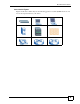
Document Conventions Icons Used in Figures Figures in this User’s Guide may use the following generic icons. The ZyXEL Device icon is not an exact representation of your device.
Safety Warnings Safety Warnings 1 For your safety, be sure to read and follow all warning notices and instructions. • Do NOT use this product near water, for example, in a wet basement or near a swimming pool. • Do NOT expose your device to dampness, dust or corrosive liquids. • Do NOT store things on the device. • Do NOT install, use, or service this device during a thunderstorm. There is a remote risk of electric shock from lightning. • Connect ONLY suitable accessories to the device.
Safety Warnings P-663H-51 User’s Guide 7
Safety Warnings 8 P-663H-51 User’s Guide
Contents Overview Contents Overview Introduction ............................................................................................................................ 23 Introducing the ZyXEL Device ................................................................................................... 25 Introducing the Web Configurator .............................................................................................. 31 Initial Configuration .................................................
Contents Overview 10 P-663H-51 User’s Guide
Table of Contents Table of Contents About This User's Guide .......................................................................................................... 3 Document Conventions............................................................................................................ 4 Safety Warnings........................................................................................................................ 6 Contents Overview .......................................................
Table of Contents 3.2 QoS Configuration ............................................................................................................... 38 3.3 Changing the Login Password ............................................................................................ 38 Chapter 4 Device Information.................................................................................................................. 39 4.1 Device Information Summary ..................................................
Table of Contents 5.13 IPoA WAN Connection Setup ........................................................................................... 63 5.14 IGMP Multicast .................................................................................................................. 63 5.15 NAT, IGMP Multicast, and WAN Service ........................................................................... 64 5.16 WAN Setup Summary .....................................................................................
Table of Contents 9.1 QoS Overview .................................................................................................................... 89 9.1.1 IEEE 802.1Q Tag ....................................................................................................... 89 9.1.2 IP Precedence ............................................................................................................ 90 9.1.3 DiffServ ................................................................................
Table of Contents Part III: Diagnostics and Management ................................................115 Chapter 16 Diagnostics ........................................................................................................................... 117 16.1 Diagnostics ......................................................................................................................117 Chapter 17 Settings..............................................................................................
Table of Contents 23.1 Save/Reboot .................................................................................................................... 139 23.2 Logout .............................................................................................................................. 139 Part IV: Troubleshooting and Specifications..................................... 141 Chapter 24 Troubleshooting....................................................................................................
List of Figures List of Figures Figure 1 Protected Internet Access Applications .................................................................................... 25 Figure 2 LAN-to-LAN Application Example ............................................................................................ 26 Figure 3 Hardware Connections ............................................................................................................ 27 Figure 4 Connecting a Microfilter ...............................
List of Figures Figure 39 Advanced Setup > NAT > DMZ Host ...................................................................................... 80 Figure 40 Advanced Setup > Security > IP Filtering > Outgoing ............................................................ 81 Figure 41 Advanced Setup > Security > IP Filtering > Outgoing > Add ................................................. 82 Figure 42 Advanced Setup > Security > IP Filtering > Incoming ......................................................
List of Figures Figure 82 DSL Connector Pin Assignments ......................................................................................... 150 Figure 83 WIndows 95/98/Me: Network: Configuration ........................................................................ 156 Figure 84 Windows 95/98/Me: TCP/IP Properties: IP Address ............................................................ 157 Figure 85 Windows 95/98/Me: TCP/IP Properties: DNS Configuration .............................................
List of Figures 20 P-663H-51 User’s Guide
List of Tables List of Tables Table 1 Front Panel LEDs ...................................................................................................................... 29 Table 2 Web Configurator Screens Summary ....................................................................................... 34 Table 3 Device Info > Summary ............................................................................................................. 39 Table 4 Device Info > WAN .................................
List of Tables Table 39 Advanced Setup > Routing > Default Gateway ...................................................................... 97 Table 40 Advanced > Routing > Static Route ........................................................................................ 99 Table 41 Advanced > Routing > Static Route > Add .............................................................................. 99 Table 42 Advanced Setup > Routing > RIP ................................................................
P ART I Introduction Introducing the ZyXEL Device (25) Introducing the Web Configurator (31) 23
CHAPTER 1 Introducing the ZyXEL Device This chapter introduces the main applications and features of the ZyXEL Device. It also introduces the ways you can manage the ZyXEL Device. 1.1 Overview The ZyXEL Device is an ADSL2+ pair bonding gateway that allows super-fast Internet access over analog (POTS) telephone lines. It bonds two ADSL2+ lines into a single logical connection to provide increased throughput at longer distances.
Chapter 1 Introducing the ZyXEL Device You can also use the ZyXEL Device to connect two geographically dispersed networks over the ADSL line. A typical LAN-to-LAN application example is shown as follows. Figure 2 LAN-to-LAN Application Example The ZyXEL Device is compatible with the ADSL/ADSL2/ADSL2+ standards. Using ADSL2+, the ZyXEL Device can attain a maximum downstream rate of about 44 Mbps.1 " The standard your ISP supports determines the maximum upstream and downstream speeds attainable.
Chapter 1 Introducing the ZyXEL Device 1.4 Hardware Connections Connect the ZyXEL Device as shown next. Figure 3 Hardware Connections 1 2 DSL1 DSL2 DSL DSL Phone Phone Line 1 Line 2 1 Connect the included DSL Y-cable. Connect the part where the two cables come together connects to the ZyXEL Device’s DSL port. 2 Connect the DSL1 end of the Y-cable to the wall jack for your first DSL line. Connect the DSL2 end of the Y-cable to the wall jack for your second DSL line.
Chapter 1 Introducing the ZyXEL Device 2 Connect the side labeled “Modem” or “DSL” to your ZyXEL Device. 3 Connect the side labeled “Line” to the telephone wall jack. 1.4.2 Telephone Microfilters Telephone voice transmissions take place in the lower frequency range, 0 - 4KHz, while ADSL transmissions take place in the higher bandwidth range, above 4KHz. A microfilter acts as a low-pass filter, for your telephone, to ensure that ADSL transmissions do not interfere with your telephone voice transmissions.
Chapter 1 Introducing the ZyXEL Device Figure 5 Front Panel The following table describes the LEDs. Table 1 Front Panel LEDs LED COLOR STATUS DESCRIPTION SYS Green On The ZyXEL Device is receiving power. ALM Red On The ZyXEL Device has malfunctioned LAN 1,2,3,4 Green On The ZyXEL Device has a successful Ethernet connection. Blinking The ZyXEL Device is sending/receiving data. Off The ZyXEL Device is not connected to the LAN. On The respective DSL line is up.
Chapter 1 Introducing the ZyXEL Device 30 P-663H-51 User’s Guide
CHAPTER 2 Introducing the Web Configurator This chapter describes how to access and navigate the web configurator. 2.1 Web Configurator Overview The web configurator is an HTML-based management interface that allows easy ZyXEL Device setup and management via Internet browser. Use Internet Explorer 6.0 and later versions. The recommended screen resolution is 1024 by 768 pixels. In order to use the web configurator you need to allow web browser pop-up windows from your device.
Chapter 2 Introducing the Web Configurator Figure 6 Password Screen 2.2.1 User Access The user account can only access the ZyXEL Device from the LAN. For user access, enter the user account’s user name (user) and password (1234 is the default) and click OK to view the status only. The following screen appears. Figure 7 User Status Screen 2.2.2 Administrator Access The admin account can only access the ZyXEL Device from the LAN.
Chapter 2 Introducing the Web Configurator " The management session automatically times out if it is left idle for five minutes. Simply log back into the ZyXEL Device if this happens. 2.3 Resetting the ZyXEL Device If you forget your password or cannot access the web configurator, you will need to use the RESET button at the back of the ZyXEL Device to reload the factory-default configuration file.
Chapter 2 Introducing the Web Configurator Table 2 Web Configurator Screens Summary LINK/ICON SUB-LINK FUNCTION Device Info Summary This screen shows general device information such as the firmware version, line rates, LAN IP address, default gateway, and DNS servers. WAN This screen displays information about the ZyXEL Device’s WAN connections. Statistics LAN This screen displays statistics about the ZyXEL Device’s LAN connections.
Chapter 2 Introducing the Web Configurator Table 2 Web Configurator Screens Summary (continued) LINK/ICON SUB-LINK FUNCTION Routing Default Gateway Set the default gateway that helps the ZyXEL Device forward traffic to its destination. Static Route Configure static routes to have the ZyXEL Device send data to devices not reachable through the default gateway. RIP Configure RIP settings to have the ZyXEL Device exchange routing information with other routers.
Chapter 2 Introducing the Web Configurator 36 P-663H-51 User’s Guide
CHAPTER 3 Initial Configuration This chapter introduces the initial configuration that you may need to perform on the ZyXEL Device. 3.1 WAN Configuration If you connect your ZyXEL Device and are able to access the Internet without configuring the ZyXEL Device, it may be that your ISP pre-configured the ZyXEL Device for you or the Internet connection works with the ZyXEL Device’s default settings.
Chapter 3 Initial Configuration 3.2 QoS Configuration If the ISP gave you QoS settings to use, click Advanced Setup > QoS and configure the ZyXEL Device to use them. See Chapter 9 on page 89 for details. If the WAN connection uses VLAN multiplexing, you can apply different QoS settings to different VLANs within the same WAN connection. If you are not using VLAN multiplexing, you may need to configure separate WAN connections (using different PVCs) in order to give different traffic different priorities.
CHAPTER 4 Device Information Use the Device Info screens to see information about your ZyXEL Device and its connections. 4.1 Device Information Summary The Device Info > Summary screen displays when you log in. To get to it from another screen, just click Device Info > Summary. This screen displays general information about the ZyXEL Device. Figure 11 Device Info > Summary The following table describes the labels shown in the Status screen.
Chapter 4 Device Information Table 3 Device Info > Summary LABEL DESCRIPTION Primary DNS Server This is the IP address of the server that the ZyXEL Device tries to use first when it needs to resolve a domain name (find the numeric IP address associated with the domain name). Secondary DNS Server If the primary server does not respond when the ZyXEL Device tries to resolve a domain name, the ZyXEL Device tries the server displayed in this field. 4.
Chapter 4 Device Information 4.3 LAN Statistics Click Device Info > Statistics > LAN to open the following screen. This screen displays statistics about the ZyXEL Device’s LAN connections. Figure 13 Device Info > Statistics > LAN The following table describes the labels in this screen. Table 5 Device Info > Statistics > LAN LABEL DESCRIPTION Interface This field displays the name of the port. Received These statistics are for traffic the ZyXEL Device has received on the LAN Ethernet interface.
Chapter 4 Device Information The following table describes the labels in this screen. Table 6 Device Info > Statistics > WAN LABEL DESCRIPTION Service If the WAN connection is using bridging, the name of the bridge displays here. VPI/VCI This field displays the WAN connection’s Virtual Path Identifier, and Virtual Channel Identifier. Protocol This is the type of network protocol the WAN interface is using for IP over Ethernet. Interface This field displays the name of the WAN connection.
Chapter 4 Device Information Table 7 Device Info > Statistics > ATM (continued) LABEL DESCRIPTION In Errors How many cells the ZyXEL Device dropped because of uncorrectable HEC errors. In Unknown How many received cells the ZyXEL Device discarded during cell header validation. This includes cells with invalid cell header patterns or unrecognized VPI/VCI values. If the ZyXEL Device is set to discard cells with undefined PTI values, they are also included in this count.
Chapter 4 Device Information Table 7 Device Info > Statistics > ATM (continued) LABEL DESCRIPTION Short Packet Errors How many PDUs that had a length shorter than the size of the AAL5 trailer (so the ZyXEL Device discarded them). Length Errors How many PDUs the ZyXEL Device discarded because the length in the AAL5 trailer did not match the PDU length. Reset Statisitcs Click this button to have the ZyXEL Device clear the current ATM statistics and start collecting them again. 4.
Chapter 4 Device Information The following table describes the labels in this screen. Table 8 Device Info > Statistics > ADSL LABEL DESCRIPTION Mode This is the ADSL mode that the ADSL link is using. Type Line Coding This shows whether the ADSL link is using Trellis coding or Reed-Solomon error correction. Trellis coding helps to reduce the noise in ADSL transmissions. Trellis may reduce throughput but it makes the connection more stable. “RS” coding stands for Reed-Solomon error correction.
Chapter 4 Device Information Table 8 Device Info > Statistics > ADSL (continued) LABEL DESCRIPTION Total ES The number of Errored SecondS that have occurred within the period. Total SES The number of Severely Errored Seconds that have occurred within the period. Total UAS The number of UnAvailable Seconds that have occurred within the period. ADSL BER Test Click this button to perform an ADSL Bit Error Rate Test to measure the quality of the ADSL connection.
Chapter 4 Device Information Click Close when you are done. 4.8 Route Info Click Device Info > Route to open the following screen. This screen displays information about the ZyXEL Device’s routes for sending traffic. Figure 19 Device Info > Route The following table describes the labels in this screen. Table 9 Device Info > Route LABEL DESCRIPTION Destination The route applies to traffic going to this network address.
Chapter 4 Device Information Click Device Info > DHCP to display the following screen. This is only available when the ZyXEL Device’s DHCP server function is enabled. The DHCP table shows current DHCP client information (including IP Address, Host Name and MAC Address) of all network clients using the ZyXEL Device’s DHCP server. Figure 20 Device Info > DHCP The following table describes the labels in this screen.
P ART II Advanced WAN Setup (51) LAN Setup (67) Network Address Translation (NAT) Screens (73) Security (81) Quality of Service (QoS) (89) Routing (97) RIP (101) DNS Setup (103) Dynamic DNS Setup (105) DSL Setup (109) Port Mapping (111) 49
CHAPTER 5 WAN Setup This chapter describes how to configure WAN settings. 5.1 WAN Overview A WAN (Wide Area Network) is an outside connection to another network or the Internet. 5.1.1 VPI and VCI Be sure to use the correct Virtual Path Identifier (VPI) and Virtual Channel Identifier (VCI) numbers assigned to you. The valid range for the VPI is 0 to 255 and for the VCI is 32 to 65535 (0 to 31 is reserved for local management of ATM traffic). Please see the appendix for more information. 5.1.
Chapter 5 WAN Setup Note: Traffic shaping controls outgoing (upstream) traffic, not incoming (downstream). Peak Cell Rate (PCR) is the maximum rate at which the sender can send cells. This parameter may be lower (but not higher) than the maximum line speed. 1 ATM cell is 53 bytes (424 bits), so a maximum speed of 832Kbps gives a maximum PCR of 1962 cells/sec. This rate is not guaranteed because it is dependent on the line speed. Sustained Cell Rate (SCR) is the mean cell rate of each bursty traffic source.
Chapter 5 WAN Setup The realtime VBR type is used with bursty connections that require closely controlled delay and delay variation. It also provides a fixed amount of bandwidth (a PCR is specified) but is only available when data is being sent. An example of an realtime VBR connection would be video conferencing. Video conferencing requires real-time data transfers and the bandwidth requirement varies in proportion to the video image's changing dynamics.
Chapter 5 WAN Setup Table 11 Advanced Setup > WAN (continued) LABEL DESCRIPTION Interface This field displays the name of the WAN connection, followed by the DSL port, Virtual Path Identifier, and Virtual Channel Identifier. Protocol This is the type of network protocol the WAN interface is using for IP over Ethernet. IGMP This is whether or not the WAN connection is using IGMP multicast (if available). QoS This is whether or not packet level QoS is enabled for the WAN connection.
Chapter 5 WAN Setup The following table describes the labels in this screen. Table 12 Advanced Setup > WAN > Add LABEL DESCRIPTION ATM PVC Configuration The PORT (interface), VPI (Virtual Path Identifier) and VCI (Virtual Channel Identifier) define an ATM PVC (Permanent Virtual Circuit). Refer to the appendix for more information. VPI Enter the VPI assigned to you for this WAN connection. VCI Enter the VCI assigned to you for this WAN connection. VLAN Mux.
Chapter 5 WAN Setup 5.5.1 PPPoA PPPoA stands for Point to Point Protocol over ATM Adaptation Layer 5 (AAL5). A PPPoA connection functions like a dial-up Internet connection. The ZyXEL Device encapsulates the PPP session based on RFC1483 and sends it through an ATM PVC (Permanent Virtual Circuit) to the Internet Service Provider’s (ISP) DSLAM (digital access multiplexer). Please refer to RFC 2364 for more information on PPPoA. Refer to RFC 1661 for more information on PPP. 5.5.
Chapter 5 WAN Setup 5.6.1 LLC-based Encapsulation In this case one VC carries multiple protocols with protocol identifying information being contained in each packet header. Despite the extra bandwidth and processing overhead, this method may be advantageous if it is not practical to have a separate VC for each carried protocol, for example, if charging heavily depends on the number of simultaneous VCs. 5.6.
Chapter 5 WAN Setup 5.8 NAT NAT (Network Address Translation - NAT, RFC 1631) is the translation of the IP address of a host in a packet, for example, the source address of an outgoing packet, used within one network to a different IP address known within another network. 5.9 Nailed-Up Connection (PPP) A nailed-up connection is a dial-up line where the connection is always up regardless of traffic demand. The ZyXEL Device does two things when you specify a nailed-up connection.
Chapter 5 WAN Setup The following table describes the labels in this screen. Table 14 Advanced Setup > WAN > Add (3: PPPoA) LABEL DESCRIPTION PPP User Name Enter the login name that your ISP gives you. PPP Password Enter the password associated with the user name above. Authentication Method The ZyXEL Device supports PAP (Password Authentication Protocol) and CHAP (Challenge Handshake Authentication Protocol). CHAP is more secure than PAP; however, PAP is readily available on more platforms.
Chapter 5 WAN Setup 5.11 PPPoE WAN Connection Setup When you select PPPoE in the second WAN setup add (or edit) screen, this screen displays next. Use this screen to configure PPPoE connection settings. Figure 26 Advanced Setup > WAN > Add (3: PPPoE) The following table describes the labels in this screen. Table 15 Advanced Setup > WAN > Add (3: PPPoE) 60 LABEL DESCRIPTION PPP User Name Enter the login name that your ISP gives you.
Chapter 5 WAN Setup Table 15 Advanced Setup > WAN > Add (3: PPPoE) (continued) LABEL DESCRIPTION Enable Full Cone NAT In full cone NAT, all requests from the same private IP address and port are mapped to the same public source IP address and port. Someone on the Internet only needs to know the mapping scheme in order to send packets to a device behind the ZyXEL Device.
Chapter 5 WAN Setup Figure 27 Advanced Setup > WAN > Add (3: MER) The following table describes the labels in this screen. Table 16 Advanced Setup > WAN > Add (3: MER) 62 LABEL DESCRIPTION Obtain an IP address automatically The WAN connection’s IP address identifies the ZyXEL Device on the Internet. If the ISP did not give you a static IP address, select Obtain an IP address automatically. The ISP automatically assigns the WAN connection an IP address when it connects.
Chapter 5 WAN Setup 5.13 IPoA WAN Connection Setup When you select IPoA in the second WAN setup add (or edit) screen, this screen displays next. Use this screen to configure IPoA connection settings. Figure 28 Advanced Setup > WAN > Add (3: IPoA) The following table describes the labels in this screen. Table 17 Advanced Setup > WAN > Add (3: IPoA) LABEL DESCRIPTION WAN IP Address Enter the IP address from the ISP. Use dotted decimal notation (like 192.168.1.1 for example).
Chapter 5 WAN Setup IGMP (Internet Group Management Protocol) is a network-layer protocol used to establish membership in a Multicast group - it is not used to carry user data. IGMP version 2 (RFC 2236) is an improvement over version 1 (RFC 1112) but IGMP version 1 is still in wide use. If you would like to read more detailed information about interoperability between IGMP version 2 and version 1, please see sections 4 and 5 of RFC 2236.
Chapter 5 WAN Setup The following table describes the labels in this screen. Table 18 Advanced Setup > WAN > Add (4: MER) LABEL DESCRIPTION Enable NAT Turn on NAT to translate IP addresses between two different networks (so you can have a private LAN with IP addresses that are different from the public IP addresses on the WAN. See Chapter 7 on page 73 for more details. Enable Fullcone NAT This field displays when you enable NAT.
Chapter 5 WAN Setup Figure 30 Advanced Setup > WAN > Add (Summary: MER) 66 P-663H-51 User’s Guide
CHAPTER 6 LAN Setup This chapter describes how to configure LAN settings. 6.1 LAN Overview A Local Area Network (LAN) is a shared communication system to which many computers are attached. A LAN is a computer network limited to the immediate area, usually the same building or floor of a building. The LAN screens can help you configure a LAN DHCP server and manage IP addresses. See Section 6.5 on page 70 to configure the LAN screens. 6.1.
Chapter 6 LAN Setup 6.1.2 DHCP Setup DHCP (Dynamic Host Configuration Protocol, RFC 2131 and RFC 2132) allows individual clients to obtain TCP/IP configuration at start-up from a server. You can configure the ZyXEL Device as a DHCP server or disable it. When configured as a server, the ZyXEL Device provides the TCP/IP configuration for the clients. If you turn DHCP service off, you must have another DHCP server on your LAN, or else the computer must be manually configured.
Chapter 6 LAN Setup • 172.16.0.0 — 172.31.255.255 • 192.168.0.0 — 192.168.255.255 You can obtain your IP address from the IANA, from an ISP or it can be assigned from a private network. If you belong to a small organization and your Internet access is through an ISP, the ISP can provide you with the Internet addresses for your local networks. On the other hand, if you are part of a much larger organization, you should consult your network administrator for the appropriate IP addresses.
Chapter 6 LAN Setup 6.4.1 How do I know if I'm using UPnP? UPnP hardware is identified as an icon in the Network Connections folder (Windows XP). Each UPnP compatible device installed on your network will appear as a separate icon. Selecting the icon of a UPnP device will allow you to access the information and properties of that device. 6.4.2 NAT Traversal UPnP NAT traversal automates the process of allowing an application to operate through NAT.
Chapter 6 LAN Setup Figure 32 Advanced Setup > LAN The following table describes the fields in this screen. Table 19 Advanced Setup > LAN LABEL DESCRIPTION IP Address Enter the LAN IP address of your ZyXEL Device in dotted decimal notation, for example, 192.168.1.1 (factory default). Subnet Mask Type the subnet mask. Enable UPnP Select this check box to activate UPnP.
Chapter 6 LAN Setup Table 19 Advanced Setup > LAN (continued) 72 LABEL DESCRIPTION Disable/Enable DHCP Server Turn on the DHCP server to have the ZyXEL Device assign IP addresses, an IP default gateway and DNS servers to DHCP clients on the LAN. Enter IP addresses in the Start and End IP Address fields to set a range of IP addresses for the ZyXEL Device to give to the DHCP clients.
CHAPTER 7 Network Address Translation (NAT) Screens This chapter discusses how to configure NAT on the ZyXEL Device. 7.1 NAT Overview NAT (Network Address Translation - NAT, RFC 1631) is the translation of the IP address of a host in a packet, for example, the source address of an outgoing packet, used within one network to a different IP address known within another network. 7.
Chapter 7 Network Address Translation (NAT) Screens 7.2.2 Virtual Servers Example Let's say you want to assign ports 21-25 to one FTP, Telnet and SMTP server (A in the example), port 80 to another (B in the example) and assign a default server IP address of 192.168.1.35 to a third (C in the example). You assign the LAN IP addresses and the ISP assigns the WAN IP address. The NAT network appears as a single host on the Internet. Figure 33 Multiple Servers Behind NAT Example 7.
Chapter 7 Network Address Translation (NAT) Screens See Appendix D on page 185 for port numbers commonly used for particular services. The following table describes the fields in this screen. Table 20 NAT Port Forwarding LABEL DESCRIPTION Add Click this button to go to a screen where you can configure a new entry. Remove To remove an entry(ies), select its Remove check box and click the Remove button. Server Name This name identifies the virtual server entry.
Chapter 7 Network Address Translation (NAT) Screens Figure 35 Advanced Setup > NAT > Virtual Servers > Add The following table describes the fields in this screen. Table 21 Advanced Setup > NAT > Virtual Servers > Add 76 LABEL DESCRIPTION Server Name Either select a pre-defined service or select Custom Server and enter a name manually. Server IP Address Enter the LAN IP address to which the ZyXEL Device should forward the traffic.
Chapter 7 Network Address Translation (NAT) Screens Table 21 Advanced Setup > NAT > Virtual Servers > Add (continued) LABEL DESCRIPTION Internal Port Start Specify the starting port the ZyXEL Device uses for the traffic that it forwards based on this virtual server entry (or leave it the same as the External Internal Port End The ZyXEL Device automatically determines this port number. Save/Apply Click this button to save the changes and have the ZyXEL Device start using them. 7.
Chapter 7 Network Address Translation (NAT) Screens 5 Only Jane can connect to the Real Audio server until the connection is closed or times out. The ZyXEL Device times out in three minutes with UDP (User Datagram Protocol) or two hours with TCP/IP (Transfer Control Protocol/Internet Protocol). Click Advanced Setup > NAT > Port Triggering to open the following screen. Use this screen to change your ZyXEL Device’s trigger port settings.
Chapter 7 Network Address Translation (NAT) Screens Figure 38 Advanced Setup > NAT > Port Triggering > Add The following table describes the labels in this screen. Table 23 Advanced Setup > NAT > Port Triggering > Add LABEL DESCRIPTION Application Name Either select a pre-defined application or select Custom Application and enter a name manually.
Chapter 7 Network Address Translation (NAT) Screens 7.6 DMZ Host In addition to the virtual servers for specified services, NAT supports a DMZ host IP address. The DMZ host receives packets from ports that are not specified in the applications in the virtual server configuration. " If you do not assign a DMZ host IP address, the ZyXEL Device discards all packets received for ports that are not specified here or in the remote management setup.
CHAPTER 8 Security This chapter describes how to configure security settings. 8.1 Outgoing IP Filtering By default, the ZyXEL Device allows traffic from the LAN to go to the Internet. Click Advanced Setup > Security > IP Filtering > Outgoing to open the following screen. This screen lists the currently configured filtering entries. Figure 40 Advanced Setup > Security > IP Filtering > Outgoing The following table describes the labels in this menu.
Chapter 8 Security 8.2 Adding Outgoing IP Filtering Rules To add an outgoing IP filtering rule, click Advanced Setup > Security > IP Filtering > Outgoing > Add. The screen appears as shown. Figure 41 Advanced Setup > Security > IP Filtering > Outgoing > Add The following table describes the labels in this menu. Table 26 Advanced Setup > Security > IP Filtering > Outgoing > Add LABEL DESCRIPTION Filter Name Type the name configured to identify the filter entry.
Chapter 8 Security Figure 42 Advanced Setup > Security > IP Filtering > Incoming The following table describes the labels in this menu. Table 27 Advanced Setup > Security > IP Filtering > Incoming LABEL DESCRIPTION Filter Name This is the name configured to identify the filter entry. VPI/VCI This is the WAN connection’s Virtual Path Identifier, and Virtual Channel Identifier. Protocol This is the type of packets to which this entry applies.
Chapter 8 Security Figure 43 Advanced Setup > Security > IP Filtering > Incoming > Add The following table describes the labels in this menu. Table 28 Advanced Setup > Security > IP Filtering > Incoming > Add LABEL DESCRIPTION Filter Name Type the name configured to identify the filter entry. Protocol Select the type of packets to which this entry applies (TCP, UDP, or both). Source IP Address Type the IP address of a computer on the Internet to which this entry applies.
Chapter 8 Security To change your ZyXEL Device’s MAC filter settings, click Advanced Setup > Security > MAC Filtering. The screen appears as shown. You need to know the MAC addresses of the devices to configure this screen. Figure 44 Advanced Setup > Security > MAC Filtering The following table describes the labels in this menu.
Chapter 8 Security 8.6 MAC Filtering Rules To add a MAC filtering rule, click Advanced Setup > Security > MAC Filtering > Add. The screen appears as shown. Figure 45 Advanced Setup > Security > MAC Filtering > Add The following table describes the labels in this menu. Table 30 Advanced Setup > Security > MAC Filtering > Add LABEL DESCRIPTION Protocol Select the type of packets to which this rule applies. Leave it blank to apply the rule to all types of packets.
Chapter 8 Security Figure 46 Advanced Setup > Security > Parental Control The following table describes the labels in this screen. Table 31 Advanced Setup > Security > Parental Control LABEL DESCRIPTION Username This name identifies to whom the blocking schedule applies. MAC This is the MAC address of the computer to which this blocking schedule applies. Mon ~ Sun These fields show to which days of the week the blocking schedule applies.
Chapter 8 Security Figure 47 Advanced Setup > Security > Parental Control > Add The following table describes the labels in this screen. Table 32 Advanced Setup > Security > Parental Control > Add 88 LABEL DESCRIPTION Username Enter a name to identify to whom the blocking schedule applies. Browser’s MAC Select this to use the MAC address of the computer you are currently using to manage the ZyXEL Device. Other MAC Address Select this to manually enter the MAC address of a computer.
CHAPTER 9 Quality of Service (QoS) This chapter contains information about configuring QoS, editing classifiers and viewing the ZyXEL Device’s QoS packet statistics. 9.1 QoS Overview Quality of Service (QoS) refers to both a network’s ability to deliver data with minimum delay, and the networking methods used to control the use of bandwidth. Without QoS, all traffic data is equally likely to be dropped when the network is congested.
Chapter 9 Quality of Service (QoS) IEEE 802.1p specifies the user priority field and defines up to eight separate traffic types. The following table describes the traffic types defined in the IEEE 802.1d standard (which incorporates the 802.1p). Table 33 IEEE 802.1p Priority Level and Traffic Type PRIORITY LEVEL TRAFFIC TYPE Level 7 Typically used for network control traffic such as router configuration messages.
Chapter 9 Quality of Service (QoS) DSCP is backward compatible with the three precedence bits in the ToS octet so that nonDiffServ compliant, ToS-enabled network device will not conflict with the DSCP mapping. DSCP (6 bits) Unused (2 bits) The DSCP value determines the forwarding behavior, the PHB (Per-Hop Behavior), that each packet gets across the DiffServ network. Based on the marking rule, different kinds of traffic can be marked for different kinds of forwarding.
Chapter 9 Quality of Service (QoS) 9.3 Queue Configuration Click Advanced > Quality of Service > Queue Configuration to open the following screen. This screen lists the QoS queues. A QoS queue sets the priority used for incoming packets that the QoS classifier has grouped into a flow. Figure 49 Advanced > Quality of Service > Queue Configuration The following table describes the labels in this screen.
Chapter 9 Quality of Service (QoS) Figure 50 Advanced > Quality of Service > Queue Configuration > Add The following table describes the labels in this screen. Table 36 Advanced > Quality of Service > Queue Configuration > Add LABEL DESCRIPTION Queue Select Enable to turn on this queue. Configuration Status Queue Select the WAN connection’s DSL port, Virtual Path Identifier, and Virtual Channel Identifier. Description This field displays any extra configured identification information.
Chapter 9 Quality of Service (QoS) Figure 51 Advanced > Quality of Service > QoS Classification The following table describes the labels in this screen. Table 37 Advanced > Quality of Service > QoS Classification 94 LABEL DESCRIPTION Class Name This is the name of the classifier. MARK These columns are the QoS setting the ZyXEL Device uses for or assigns to the packets of upstream traffic that match this QoS classifier.
Chapter 9 Quality of Service (QoS) 9.5.1 Configuring a QoS Class Click Advanced > Quality of Service > QoS Classification and then the Add or Edit button to configure a classifier. There are two sets of classification rules. Set-1 is based on different fields within the TCP/UDP/IP layer plus the physical LAN port. Set-2 is based on the MAC layer IEEE 802.1p priority field. Use one set or the other for a class (not both sets).
Chapter 9 Quality of Service (QoS) Table 38 QoS Class Configuration (continued) 96 LABEL DESCRIPTION Rule Status Select whether or not the classifier is to be active. Assign Classification Queue Select the QoS queue the ZyXEL Device uses for the packets of upstream traffic that match this QoS classifier. Assign Differentiated Services Code Point (DSCP) Mark Select the DSCP mark the ZyXEL Device assigns to the packets of upstream traffic that match this QoS classifier. Mark 802.1p if 802.
CHAPTER 10 Routing This chapter shows you how to configure the default gateway and static routes for your ZyXEL Device. 10.1 Default Gateway Setup The default gateway is a neighboring router that helps the ZyXEL Device forward traffic to its destination. Click Advanced > Routing > Default Gateway to open the following screen. Use this screen to change the ZyXEL Device’s default gateway settings. Figure 53 Advanced Setup > Routing > Default Gateway The following table describes the labels in this screen.
Chapter 10 Routing 10.2 Static Route The ZyXEL Device usually uses the default gateway to route outbound traffic from local computers to the Internet. To have the ZyXEL Device send data to devices not reachable through the default gateway, use static routes. For example, the next figure shows a computer (A) connected to the ZyXEL Device’s LAN interface. The ZyXEL Device routes most traffic from A to the Internet through the default gateway (R1).
Chapter 10 Routing The following table describes the labels in this screen. Table 40 Advanced > Routing > Static Route LABEL DESCRIPTION Destination This parameter specifies the IP network address of the final destination. Routing is always based on network number. Subnet Mask This is the IP subnet mask. Gateway This is the IP address of the gateway. The gateway is a router or switch on the same network segment as the device's LAN or WAN port. The gateway helps forward packets to their destinations.
Chapter 10 Routing Table 41 Advanced > Routing > Static Route > Add 100 LABEL DESCRIPTION Interface If the static route should send traffic through a specific ZyXEL Device interface, select this option and choose the interface. Save/Apply Click this button to save the changes and have the ZyXEL Device start using them.
CHAPTER 11 RIP This chapter covers configuring the RIP settings for your ZyXEL Device. 11.1 RIP Setup RIP (Routing Information Protocol, RFC 1058 and RFC 1389) allows a router to exchange routing information with other routers. RIP Direction controls the sending and receiving of RIP packets. When set to Both or Out Only, the ZyXEL Device will broadcast its routing table periodically.
Chapter 11 RIP The following table describes the labels in this screen. Table 42 Advanced Setup > Routing > RIP 102 LABEL DESCRIPTION Global RIP Mode Use these fields to turn RIP on or off for the whole ZyXEL Device. When you disable RIP, the ZyXEL Device will not send any RIP packets and will ignore any RIP packets received. Interface This field displays the name of the WAN connection.
CHAPTER 12 DNS Setup This chapter describes how to configure DNS settings. 12.1 DNS Server Address DNS (Domain Name System) maps a domain name to its corresponding IP address and vice versa. The DNS server is extremely important because without it, you must know the IP address of a computer before you can access it. The DNS server addresses you enter when you set up DHCP are passed to the client machines along with the assigned IP address and subnet mask.
Chapter 12 DNS Setup Figure 58 Advanced Setup > DNS > DNS Server The following table describes the fields in this screen. Table 43 Advanced Setup > DNS > DNS Server 104 LABEL DESCRIPTION Enable Automatic Assigned DNS Select this option to have the ZyXEL Device accept and use the first DNS server IP address it gets from a WAN connection. Primary DNS server Secondary DNS server These fields are available when you clear Enable Automatic Assigned DNS.
CHAPTER 13 Dynamic DNS Setup This chapter discusses how to configure your ZyXEL Device to use Dynamic DNS. 13.1 Dynamic DNS Overview Dynamic DNS allows you to update your current dynamic IP address with one or many dynamic DNS services so that anyone can contact you (in NetMeeting, CU-SeeMe, etc.). You can also access your FTP server or Web site on your own computer using a domain name (for instance myhost.dhs.
Chapter 13 Dynamic DNS Setup The following table describes the fields in this screen. Table 44 Advanced Setup > DNS > Dynamic DNS LABEL DESCRIPTION Host Name This is the domain name assigned to your ZyXEL Device by your Dynamic DNS provider. User Name This is the user name for the host name’s DDNS account. Service This is the name of your Dynamic DNS service provider. Interface This is the ZyXEL Device’s WAN connection that uses this DDNS host name.
Chapter 13 Dynamic DNS Setup Table 45 Advanced Setup > DNS > Dynamic DNS > Add (continued) LABEL DESCRIPTION Password Type the password assigned for this DDNS host name. Save/Apply Click this button to save the changes and have the ZyXEL Device start using them.
Chapter 13 Dynamic DNS Setup 108 P-663H-51 User’s Guide
CHAPTER 14 DSL Setup This chapter explains how to configure ADSL port settings. 14.1 DSL Setup Click Advanced > DSL to open the following screen where you can configure the ZyXEL Device’s DSL settings. Figure 61 Advanced > DSL The following table describes the labels in this screen. Table 46 Advanced > DSL LABEL DESCRIPTION Select the modulation below Select the port’s ADSL operational mode. Select multiple modes to let the ZyXEL Device and the DSLAM automatically determine the mode to use.
Chapter 14 DSL Setup Table 46 Advanced > DSL (continued) 110 LABEL DESCRIPTION SRA Enable Enable Seamless Rate Adaptation (SRA) to have the ZyXEL Device automatically adjust the connection’s data rate according to line conditions without interrupting service. Save/Apply Click this button to save the changes and have the ZyXEL Device start using them.
CHAPTER 15 Port Mapping This chapter explains how to map ports to PVCs and create bridging groups. 15.1 Port Mapping Setup Click Advanced Setup > Port Mapping to open the following screen. Use this screen to map ports to PVCs and create bridging groups. Figure 62 Advanced Setup > Port Mapping The following table describes the labels in this screen.
Chapter 15 Port Mapping Table 47 Advanced Setup > Port Mapping (continued) LABEL DESCRIPTION Edit Click Edit to configure the group’s settings. Interfaces These are the interfaces that belong to the group. Enable/Disable Use this column to turn an individual interface on or off. Add Click Add to open a screen where you can add a new entry. Save/Apply Click this button to save the changes and have the ZyXEL Device start using them. 15.
Chapter 15 Port Mapping The following table describes the labels in this screen. Table 48 Advanced Setup > Port Mapping > Add LABEL DESCRIPTION Group Name Configure a name to identify the group. Grouped Interfaces Available Interfaces Select interfaces to add to the group. Automatically Add Clients With the following DHCP Vendor IDs If you want LAN clients to get public IP addresses, you can list their DHCP vendor IDs here.
Chapter 15 Port Mapping 114 P-663H-51 User’s Guide
P ART III Diagnostics and Management Diagnostics (117) Settings (119) Logs (123) SNMP (127) Time (131) Access Control (133) Update Software (137) Save/Reboot and Logout (139) 115
CHAPTER 16 Diagnostics These read-only screens display information to help you identify problems with the ZyXEL Device. 16.1 Diagnostics Click Diagnostics to open the screen shown next. Use this screen to test the ZyXEL Devices connections. The ENET connections appear as four separate connections when you enable virtual ports (see Chapter 15 on page 111), otherwise they appear as a single connection. Both ADSL lines must be connected and working to pass the ADSL synchronization test.
Chapter 16 Diagnostics 118 P-663H-51 User’s Guide
CHAPTER 17 Settings This chapter describes how to manage your ZyXEL Device’s configuration. 17.1 Backup Configuration Using the Web Configurator Click Management > Settings > Backup to open the following screen. Use this screen to back up (save) the ZyXEL Device’s current configuration to a file on your computer. Once your ZyXEL Device is configured and functioning properly, it is highly recommended that you back up your configuration file before making configuration changes.
Chapter 17 Settings Table 49 Management > Settings > Update 1 LABEL DESCRIPTION Settings File Name Type in the location of the file you want to upload in this field or click Browse... to find it. Browse... Click Browse... to find the file you want to upload. Remember that you must decompress compressed (.ZIP) files before you can upload them. Update Settings Click this to begin the upload process.
Chapter 17 Settings You may need to change the IP address of your computer to be in the same subnet as that of the default ZyXEL Device IP address (192.168.1.1). See the appendix for details on how to set up your computer’s IP address.
Chapter 17 Settings 122 P-663H-51 User’s Guide
CHAPTER 18 Logs This chapter contains information about configuring general log settings and viewing the ZyXEL Device’s logs. Refer to the appendix for example log message explanations. 18.1 Logs Overview The web configurator allows you to choose which levels of events to have the ZyXEL Device log and then display the logs or have the ZyXEL Device send them to an administrator (as email) or to a syslog server. 18.2 System Log Click Management > System Log to open the following screen.
Chapter 18 Logs Figure 70 Management > System Log > View System Log The following table describes the fields in this screen. Table 50 Management > System Log > View System Log LABEL DESCRIPTION Date/Time This field displays when the log was recorded. Facility This is the log’s category. Severity This is the event’s degree of seriousness. Message This field states the reason for the log. Refresh Click Refresh to renew the log screen. Close Click this to close the window. 18.
Chapter 18 Logs The following table describes the fields in this screen. Table 51 Management > System Log > Configure System Log LABEL DESCRIPTION Log This controls whether or not the ZyXEL Device logs events. Log Level Select the lowest level of events that you want the ZyXEL Device to log. The ZyXEL Device logs all events with that severity level or higher. Display Level Select the lowest level of events that you want the ZyXEL Device to display.
Chapter 18 Logs 126 P-663H-51 User’s Guide
CHAPTER 19 SNMP This chapter provides information on the SNMP screen. 19.1 SNMP Simple Network Management Protocol is a protocol used for exchanging management information between network devices. SNMP is a member of TCP/IP protocol suite. A manager station can monitor the ZyXEL Device through the network via SNMP version one (SNMPv1) and/or SNMP version 2c. The next figure illustrates an SNMP management operation. SNMP is only available if TCP/IP is configured.
Chapter 19 SNMP An agent is a management software module that resides in a managed device (the ZyXEL Device). An agent translates the local management information from the managed device into a form compatible with SNMP. The manager is the console through which network administrators perform network management functions. It executes applications that control and monitor managed devices.
Chapter 19 SNMP 19.2 SNMP Screen To open this screen, click Advanced Application, Access Control, SNMP. Figure 73 SNMP The following table describes the labels in this screen. Table 53 SNMP LABEL DESCRIPTION SNMP Agent Enable the SNMP agent to turn on SNMP on the ZyXEL Device. Read Community Enter the get community, which is the password for the incoming Get- and GetNext- requests from the management station.
Chapter 19 SNMP 130 P-663H-51 User’s Guide
CHAPTER 20 Time This chapter covers how to set the time in the ZyXEL Device. 20.1 Time Setup Click Management > Internet Time to open the following screen. Use this screen to configure how the ZyXEL Device synchronizes its internal clock with a time server on the Internet. Figure 74 Management > Internet Time The following table describes the labels in this screen.
Chapter 20 Time 132 P-663H-51 User’s Guide
CHAPTER 21 Access Control This chapter describes how to configure access control. 21.1 Access Control Screen Use the access control screens to enable or disable service access to the ZyXEL Device. 21.2 Service Access Control Screen To open this screen, click Management > Access Control > Services. Figure 75 Management > Access Control > Services The following table describes the labels in this screen.
Chapter 21 Access Control Table 55 Management > Access Control > Services LABEL DESCRIPTION LAN Select the Enable check boxes for the corresponding services that you want to allow to access the ZyXEL Device from the LAN. Save/Apply Click this button to save the changes and have the ZyXEL Device start using them. 21.3 IP Addresses This screen lists the IP addresses of trusted computers that may manage the ZyXEL Device. To open this screen, click Management > Access Control > IP Addresses.
Chapter 21 Access Control 21.4 Adding IP Addresses Use this screen to add IP addresses of trusted computers that may manage the ZyXEL Device. To open this screen, click Management > Access Control > IP Addresses > Add. Figure 77 Management > Access Control > IP Addresses > Add The following table describes the labels in this screen.
Chapter 21 Access Control Figure 78 Management > Access Control > Passwords The following table describes the labels in this screen. Table 58 Management > Access Control > Passwords 136 LABEL DESCRIPTION Username Select the user name for which you want to configure the password. The admin or user account can only access the ZyXEL Device from the LAN. The support account can only access the ZyXEL Device from the WAN. Only the admin or support account can use Telnet to log into the ZyXEL Device.
CHAPTER 22 Update Software This chapter covers upgrading the ZyXEL Device’s firmware. 22.1 Uploading Firmware The software embedded in the ZyXEL Device is called “firmware”. Find firmware at www.zyxel.com in a file that (usually) uses the system model name with a .bin extension, for example, "ZyXEL Device.bin". The upload process described here may take up to two minutes. After a successful upload, the system will reboot. 1 Only use firmware for your device’s specific model.
Chapter 22 Update Software Table 59 Management > Update Software (continued) 1 LABEL DESCRIPTION Browse... Click Browse... to find the .bin file you want to upload. Remember that you must decompress compressed (.zip) files before you can upload them. Update Software Click Upload to begin the upload process. This process may take up to two minutes. Do NOT turn off the ZyXEL Device while firmware upload is in progress! After you upload firmware, wait before logging into the ZyXEL Device again.
CHAPTER 23 Save/Reboot and Logout This chapter covers the save and reboot screen. 23.1 Save/Reboot Click Management > Save/Reboot to open the following screen. Click Save/Reboot to save all of your ZyXEL Device’s settings and reboot the ZyXEL Device without turning the power off. Figure 81 Management > Save/Reboot 23.2 Logout Click Management > Logout to exit the web configurator.
Chapter 23 Save/Reboot and Logout 140 P-663H-51 User’s Guide
P ART IV Troubleshooting and Specifications Troubleshooting (143) Product Specifications (147) 141
CHAPTER 24 Troubleshooting This chapter offers some suggestions to solve problems you might encounter. The potential problems are divided into the following categories. • Power, Hardware Connections, and LEDs • ZyXEL Device Access and Login • Internet Access 24.1 Power, Hardware Connections, and LEDs V The ZyXEL Device does not turn on. None of the LEDs turn on. 1 Make sure the ZyXEL Device is turned on. 2 Make sure you are using the power adaptor or cord included with the ZyXEL Device.
Chapter 24 Troubleshooting 24.2 ZyXEL Device Access and Login V I forgot the IP address for the ZyXEL Device. 1 The default IP address is 192.168.1.1. 2 If you changed the IP address and have forgotten it, you might get the IP address of the ZyXEL Device by looking up the IP address of the default gateway for your computer. To do this in most Windows computers, click Start > Run, enter cmd, and then enter ipconfig.
Chapter 24 Troubleshooting 6 If the problem continues, contact the network administrator or vendor, or try one of the advanced suggestions. V I can see the Login screen, but I cannot log in to the ZyXEL Device. 1 Make sure you have entered the user name and password correctly. The default password is 1234. This field is case-sensitive, so make sure [Caps Lock] is not on. 2 Turn the ZyXEL Device off and on. 3 If this does not work, you have to reset the device to its factory defaults. See Section 2.
Chapter 24 Troubleshooting 1 There might be a lot of traffic on the network. Look at the LEDs, and check Section 1.5 on page 28. If the ZyXEL Device is sending or receiving a lot of information, try closing some programs that use the Internet, especially peer-to-peer applications. 2 Reboot the ZyXEL Device. 3 Turn the ZyXEL Device off and on. 4 If the problem continues, contact the network administrator or vendor, or try one of the advanced suggestions.
CHAPTER 25 Product Specifications The following tables summarize the ZyXEL Device’s hardware and firmware features. Table 60 Device Specifications Dimensions (W x D x H) 50.4 x 207 x 160.8 mm Power Specification 12 VDC 1.
Chapter 25 Product Specifications Table 61 Firmware Specifications FEATURE DESCRIPTION Other Protocol Support PPP (Point-to-Point Protocol) link layer protocol. Transparent bridging for unsupported network layer protocols. DHCP Server/Client/Relay RIP I / RIP II ICMP ATM QoS SNMP v1 and v2c with MIB II support (RFC 1213) IP Multicasting IGMP v1 and v2 IGMP Proxy UPnP Management Use the embedded web configurator to easily configure the rich range of features on the ZyXEL Device.
Chapter 25 Product Specifications Table 61 Firmware Specifications FEATURE DESCRIPTION Universal Plug and Play (UPnP) A UPnP-enabled device can dynamically join a network, obtain an IP address and convey its capabilities to other devices on the network. Firewall You can configure firewall on the ZyXEL Device for secure Internet access. When the firewall is on, by default, all incoming traffic from the Internet to your network is blocked unless it is initiated from your network.
Chapter 25 Product Specifications 25.1 DSL Connector Pin Assignments The ZyXEL Device’s RJ-11 DSL connector handles both the DSL 1 and DSL 2 connections. • Pins 3 and 4 are for DSL 1. • Pins 2 and 5 are for DSL 2. Figure 82 DSL Connector Pin Assignments DSL 2 DSL 1 1 2 3 4 5 6 25.2 Power Adaptor Specifications Table 63 North American Plug Standards AC POWER ADAPTOR MODEL PSA18R-120P (ZA)-R INPUT POWER 100-240VAC, 50/60HZ, 0.5A OUTPUT POWER 12VDC, 1.5A POWER CONSUMPTION 18 W MAX.
Chapter 25 Product Specifications Table 65 United Kingdom Plug Standards POWER CONSUMPTION 18 W MAX.
Chapter 25 Product Specifications 152 P-663H-51 User’s Guide
P ART V Appendices and Index Setting up Your Computer’s IP Address (155) IP Addresses and Subnetting (171) Pop-up Windows (181) Common Services (185) Legal Information (189) Customer Support (193) Index (199) 153
APPENDIX A Setting up Your Computer’s IP Address All computers must have a 10M or 100M Ethernet adapter card and TCP/IP installed. Windows 95/98/Me/NT/2000/XP, Macintosh OS 7 and later operating systems and all versions of UNIX/LINUX include the software components you need to install and use TCP/ IP on your computer. Windows 3.1 requires the purchase of a third-party TCP/IP application package.
Appendix A Setting up Your Computer’s IP Address Figure 83 WIndows 95/98/Me: Network: Configuration Installing Components The Network window Configuration tab displays a list of installed components. You need a network adapter, the TCP/IP protocol and Client for Microsoft Networks. If you need the adapter: 1 In the Network window, click Add. 2 Select Adapter and then click Add. 3 Select the manufacturer and model of your network adapter and then click OK.
Appendix A Setting up Your Computer’s IP Address Configuring 1 In the Network window Configuration tab, select your network adapter's TCP/IP entry and click Properties 2 Click the IP Address tab. • If your IP address is dynamic, select Obtain an IP address automatically. • If you have a static IP address, select Specify an IP address and type your information into the IP Address and Subnet Mask fields. Figure 84 Windows 95/98/Me: TCP/IP Properties: IP Address 3 Click the DNS Configuration tab.
Appendix A Setting up Your Computer’s IP Address Figure 85 Windows 95/98/Me: TCP/IP Properties: DNS Configuration 4 Click the Gateway tab. • If you do not know your gateway’s IP address, remove previously installed gateways. • If you have a gateway IP address, type it in the New gateway field and click Add. 5 Click OK to save and close the TCP/IP Properties window. 6 Click OK to close the Network window. Insert the Windows CD if prompted.
Appendix A Setting up Your Computer’s IP Address Figure 86 Windows XP: Start Menu 2 In the Control Panel, double-click Network Connections (Network and Dial-up Connections in Windows 2000/NT). Figure 87 Windows XP: Control Panel 3 Right-click Local Area Connection and then click Properties.
Appendix A Setting up Your Computer’s IP Address Figure 88 Windows XP: Control Panel: Network Connections: Properties 4 Select Internet Protocol (TCP/IP) (under the General tab in Win XP) and then click Properties. Figure 89 Windows XP: Local Area Connection Properties 5 The Internet Protocol TCP/IP Properties window opens (the General tab in Windows XP). • If you have a dynamic IP address click Obtain an IP address automatically.
Appendix A Setting up Your Computer’s IP Address Figure 90 Windows XP: Internet Protocol (TCP/IP) Properties 6 If you do not know your gateway's IP address, remove any previously installed gateways in the IP Settings tab and click OK. Do one or more of the following if you want to configure additional IP addresses: • In the IP Settings tab, in IP addresses, click Add. • In TCP/IP Address, type an IP address in IP address and a subnet mask in Subnet mask, and then click Add.
Appendix A Setting up Your Computer’s IP Address Figure 91 Windows XP: Advanced TCP/IP Properties 7 In the Internet Protocol TCP/IP Properties window (the General tab in Windows XP): • Click Obtain DNS server address automatically if you do not know your DNS server IP address(es). • If you know your DNS server IP address(es), click Use the following DNS server addresses, and type them in the Preferred DNS server and Alternate DNS server fields.
Appendix A Setting up Your Computer’s IP Address Figure 92 Windows XP: Internet Protocol (TCP/IP) Properties 8 Click OK to close the Internet Protocol (TCP/IP) Properties window. 9 Click Close (OK in Windows 2000/NT) to close the Local Area Connection Properties window. 10 Close the Network Connections window (Network and Dial-up Connections in Windows 2000/NT). 11 Turn on your ZyXEL Device and restart your computer (if prompted).
Appendix A Setting up Your Computer’s IP Address Figure 93 Macintosh OS 8/9: Apple Menu 2 Select Ethernet built-in from the Connect via list. Figure 94 Macintosh OS 8/9: TCP/IP 3 For dynamically assigned settings, select Using DHCP Server from the Configure: list. 4 For statically assigned settings, do the following: • From the Configure box, select Manually.
Appendix A Setting up Your Computer’s IP Address • Type your IP address in the IP Address box. • Type your subnet mask in the Subnet mask box. • Type the IP address of your ZyXEL Device in the Router address box. 5 Close the TCP/IP Control Panel. 6 Click Save if prompted, to save changes to your configuration. 7 Turn on your ZyXEL Device and restart your computer (if prompted). Verifying Settings Check your TCP/IP properties in the TCP/IP Control Panel window.
Appendix A Setting up Your Computer’s IP Address Figure 96 Macintosh OS X: Network 4 For statically assigned settings, do the following: • From the Configure box, select Manually. • Type your IP address in the IP Address box. • Type your subnet mask in the Subnet mask box. • Type the IP address of your ZyXEL Device in the Router address box. 5 Click Apply Now and close the window. 6 Turn on your ZyXEL Device and restart your computer (if prompted).
Appendix A Setting up Your Computer’s IP Address " Make sure you are logged in as the root administrator. Using the K Desktop Environment (KDE) Follow the steps below to configure your computer IP address using the KDE. 1 Click the Red Hat button (located on the bottom left corner), select System Setting and click Network. Figure 97 Red Hat 9.0: KDE: Network Configuration: Devices 2 Double-click on the profile of the network card you wish to configure.
Appendix A Setting up Your Computer’s IP Address • If you have a dynamic IP address click Automatically obtain IP address settings with and select dhcp from the drop down list. • If you have a static IP address click Statically set IP Addresses and fill in the Address, Subnet mask, and Default Gateway Address fields. 3 Click OK to save the changes and close the Ethernet Device General screen. 4 If you know your DNS server IP address(es), click the DNS tab in the Network Configuration screen.
Appendix A Setting up Your Computer’s IP Address Figure 101 Red Hat 9.0: Dynamic IP Address Setting in ifconfig-eth0 DEVICE=eth0 ONBOOT=yes BOOTPROTO=dhcp USERCTL=no PEERDNS=yes TYPE=Ethernet • If you have a static IP address, enter static in the BOOTPROTO= field. Type IPADDR= followed by the IP address (in dotted decimal notation) and type NETMASK= followed by the subnet mask. The following example shows an example where the static IP address is 192.168.1.10 and the subnet mask is 255.255.255.0.
Appendix A Setting up Your Computer’s IP Address Verifying Settings Enter ifconfig in a terminal screen to check your TCP/IP properties. Figure 105 Red Hat 9.0: Checking TCP/IP Properties [root@localhost]# ifconfig eth0 Link encap:Ethernet HWaddr 00:50:BA:72:5B:44 inet addr:172.23.19.129 Bcast:172.23.19.255 Mask:255.255.255.
APPENDIX B IP Addresses and Subnetting This appendix introduces IP addresses and subnet masks. IP addresses identify individual devices on a network. Every networking device (including computers, servers, routers, printers, etc.) needs an IP address to communicate across the network. These networking devices are also known as hosts. Subnet masks determine the maximum number of possible hosts on a network. You can also use subnet masks to divide one network into multiple sub-networks.
Appendix B IP Addresses and Subnetting Figure 106 Network Number and Host ID How much of the IP address is the network number and how much is the host ID varies according to the subnet mask. Subnet Masks A subnet mask is used to determine which bits are part of the network number, and which bits are part of the host ID (using a logical AND operation). The term “subnet” is short for “subnetwork”. A subnet mask has 32 bits.
Appendix B IP Addresses and Subnetting Subnet masks are expressed in dotted decimal notation just like IP addresses. The following examples show the binary and decimal notation for 8-bit, 16-bit, 24-bit and 29-bit subnet masks. Table 67 Subnet Masks BINARY DECIMAL 1ST OCTET 2ND OCTET 3RD OCTET 4TH OCTET 8-bit mask 11111111 00000000 00000000 00000000 255.0.0.0 16-bit mask 11111111 11111111 00000000 00000000 255.255.0.0 24-bit mask 11111111 11111111 11111111 00000000 255.255.255.
Appendix B IP Addresses and Subnetting Table 69 Alternative Subnet Mask Notation (continued) SUBNET MASK ALTERNATIVE NOTATION LAST OCTET (BINARY) LAST OCTET (DECIMAL) 255.255.255.192 /26 1100 0000 192 255.255.255.224 /27 1110 0000 224 255.255.255.240 /28 1111 0000 240 255.255.255.248 /29 1111 1000 248 255.255.255.252 /30 1111 1100 252 Subnetting You can use subnetting to divide one network into multiple sub-networks.
Appendix B IP Addresses and Subnetting Figure 108 Subnetting Example: After Subnetting In a 25-bit subnet the host ID has 7 bits, so each sub-network has a maximum of 27 – 2 or 126 possible hosts (a host ID of all zeroes is the subnet’s address itself, all ones is the subnet’s broadcast address). 192.168.1.0 with mask 255.255.255.128 is subnet A itself, and 192.168.1.127 with mask 255.255.255.128 is its broadcast address.
Appendix B IP Addresses and Subnetting Table 71 Subnet 2 IP/SUBNET MASK NETWORK NUMBER LAST OCTET BIT VALUE IP Address 192.168.1. 64 IP Address (Binary) 11000000.10101000.00000001. 01000000 Subnet Mask (Binary) 11111111.11111111.11111111. 11000000 Subnet Address: 192.168.1.64 Lowest Host ID: 192.168.1.65 Broadcast Address: 192.168.1.127 Highest Host ID: 192.168.1.126 Table 72 Subnet 3 IP/SUBNET MASK NETWORK NUMBER LAST OCTET BIT VALUE IP Address 192.168.1.
Appendix B IP Addresses and Subnetting Table 74 Eight Subnets (continued) SUBNET SUBNET ADDRESS FIRST ADDRESS LAST ADDRESS BROADCAST ADDRESS 5 128 129 158 159 6 160 161 190 191 7 192 193 222 223 8 224 225 254 255 Subnet Planning The following table is a summary for subnet planning on a network with a 24-bit network number. Table 75 24-bit Network Number Subnet Planning NO. “BORROWED” HOST BITS SUBNET MASK NO. SUBNETS NO. HOSTS PER SUBNET 1 255.255.255.
Appendix B IP Addresses and Subnetting Table 76 16-bit Network Number Subnet Planning (continued) NO. “BORROWED” HOST BITS SUBNET MASK NO. SUBNETS NO. HOSTS PER SUBNET 14 255.255.255.252 (/30) 16384 2 15 255.255.255.254 (/31) 32768 1 Configuring IP Addresses Where you obtain your network number depends on your particular situation. If the ISP or your network administrator assigns you a block of registered IP addresses, follow their instructions in selecting the IP addresses and the subnet mask.
Appendix B IP Addresses and Subnetting IP Address Conflicts Each device on a network must have a unique IP address. Devices with duplicate IP addresses on the same network will not be able to access the Internet or other resources. The devices may also be unreachable through the network. Conflicting Computer IP Addresses Example More than one device can not use the same IP address.
Appendix B IP Addresses and Subnetting Conflicting Computer and Router IP Addresses Example More than one device can not use the same IP address. In the following example, the computer and the router’s LAN port both use 192.168.1.1 as the IP address. The computer cannot access the Internet. This problem can be solved by assigning a different IP address to the computer or the router’s LAN port.
APPENDIX C Pop-up Windows In order to use the web configurator you need to allow web browser pop-up windows from your device. " Internet Explorer 6 screens are used here. Screens for other Internet Explorer versions may vary. Internet Explorer Pop-up Blockers You may have to disable pop-up blocking to log into your device. Either disable pop-up blocking (enabled by default in Windows XP SP (Service Pack) 2) or allow pop-up blocking and create an exception for your device’s IP address.
Appendix C Pop-up Windows Figure 113 Internet Options: Privacy 3 Click Apply to save this setting. Enable pop-up Blockers with Exceptions Alternatively, if you only want to allow pop-up windows from your device, see the following steps. 1 In Internet Explorer, select Tools, Internet Options and then the Privacy tab. 2 Select Settings…to open the Pop-up Blocker Settings screen.
Appendix C Pop-up Windows Figure 114 Internet Options: Privacy 3 Type the IP address of your device (the web page that you do not want to have blocked) with the prefix “http://”. For example, http://192.168.167.1. 4 Click Add to move the IP address to the list of Allowed sites.
Appendix C Pop-up Windows 5 Click Close to return to the Privacy screen. 6 Click Apply to save this setting.
APPENDIX D Common Services The following table lists some commonly-used services and their associated protocols and port numbers. For a comprehensive list of port numbers, ICMP type/code numbers and services, visit the IANA (Internet Assigned Number Authority) web site. • Name: This is a short, descriptive name for the service. You can use this one or create a different one, if you like. • Protocol: This is the type of IP protocol used by the service.
Appendix D Common Services Table 77 Commonly Used Services (continued) 186 NAME PROTOCOL PORT(S) DESCRIPTION FTP TCP TCP 20 21 File Transfer Program, a program to enable fast transfer of files, including large files that may not be possible by e-mail. H.323 TCP 1720 NetMeeting uses this protocol. HTTP TCP 80 Hyper Text Transfer Protocol - a client/ server protocol for the world wide web. HTTPS TCP 443 HTTPS is a secured http session often used in e-commerce.
Appendix D Common Services Table 77 Commonly Used Services (continued) NAME PROTOCOL PORT(S) DESCRIPTION RTSP TCP/UDP 554 The Real Time Streaming (media control) Protocol (RTSP) is a remote control for multimedia on the Internet. SFTP TCP 115 Simple File Transfer Protocol. SMTP TCP 25 Simple Mail Transfer Protocol is the message-exchange standard for the Internet. SMTP enables you to move messages from one e-mail server to another. SNMP TCP/UDP 161 Simple Network Management Program.
Appendix D Common Services 188 P-663H-51 User’s Guide
APPENDIX E Legal Information Copyright Copyright © 2007 by ZyXEL Communications Corporation. The contents of this publication may not be reproduced in any part or as a whole, transcribed, stored in a retrieval system, translated into any language, or transmitted in any form or by any means, electronic, mechanical, magnetic, optical, chemical, photocopying, manual, or otherwise, without the prior written permission of ZyXEL Communications Corporation. Published by ZyXEL Communications Corporation.
Appendix E Legal Information If this device does cause harmful interference to radio/television reception, which can be determined by turning the device off and on, the user is encouraged to try to correct the interference by one or more of the following measures: 1 Reorient or relocate the receiving antenna. 2 Increase the separation between the equipment and the receiver. 3 Connect the equipment into an outlet on a circuit different from that to which the receiver is connected.
Appendix E Legal Information ZyXEL) and the customer will be billed for parts and labor. All repaired or replaced products will be shipped by ZyXEL to the corresponding return address, Postage Paid. This warranty gives you specific legal rights, and you may also have other rights that vary from country to country. Registration Register your product online to receive e-mail notices of firmware upgrades and information at www.zyxel.com for global products, or at www.us.zyxel.com for North American products.
Appendix E Legal Information 192 P-663H-51 User’s Guide
APPENDIX F Customer Support Please have the following information ready when you contact customer support. Required Information • • • • Product model and serial number. Warranty Information. Date that you received your device. Brief description of the problem and the steps you took to solve it. “+” is the (prefix) number you dial to make an international telephone call. Corporate Headquarters (Worldwide) • • • • • • • Support E-mail: support@zyxel.com.tw Sales E-mail: sales@zyxel.com.
Appendix F Customer Support • Regular Mail: ZyXEL Communications, Czech s.r.o., Modranská 621, 143 01 Praha 4 Modrany, Ceská Republika Denmark • • • • • • Support E-mail: support@zyxel.dk Sales E-mail: sales@zyxel.dk Telephone: +45-39-55-07-00 Fax: +45-39-55-07-07 Web: www.zyxel.dk Regular Mail: ZyXEL Communications A/S, Columbusvej, 2860 Soeborg, Denmark Finland • • • • • • Support E-mail: support@zyxel.fi Sales E-mail: sales@zyxel.fi Telephone: +358-9-4780-8411 Fax: +358-9-4780-8448 Web: www.zyxel.
Appendix F Customer Support India • • • • • • Support E-mail: support@zyxel.in Sales E-mail: sales@zyxel.in Telephone: +91-11-30888144 to +91-11-30888153 Fax: +91-11-30888149, +91-11-26810715 Web: http://www.zyxel.in Regular Mail: India - ZyXEL Technology India Pvt Ltd., II-Floor, F2/9 Okhla Phase -1, New Delhi 110020, India Japan • • • • • • Support E-mail: support@zyxel.co.jp Sales E-mail: zyp@zyxel.co.jp Telephone: +81-3-6847-3700 Fax: +81-3-6847-3705 Web: www.zyxel.co.
Appendix F Customer Support • Regular Mail: ZyXEL Communications Inc., 1130 N. Miller St., Anaheim, CA 928062001, U.S.A. Norway • • • • • • Support E-mail: support@zyxel.no Sales E-mail: sales@zyxel.no Telephone: +47-22-80-61-80 Fax: +47-22-80-61-81 Web: www.zyxel.no Regular Mail: ZyXEL Communications A/S, Nils Hansens vei 13, 0667 Oslo, Norway Poland • • • • • E-mail: info@pl.zyxel.com Telephone: +48-22-333 8250 Fax: +48-22-333 8251 Web: www.pl.zyxel.com Regular Mail: ZyXEL Communications, ul.
Appendix F Customer Support Sweden • • • • • • Support E-mail: support@zyxel.se Sales E-mail: sales@zyxel.se Telephone: +46-31-744-7700 Fax: +46-31-744-7701 Web: www.zyxel.se Regular Mail: ZyXEL Communications A/S, Sjöporten 4, 41764 Göteborg, Sweden Thailand • • • • • • Support E-mail: support@zyxel.co.th Sales E-mail: sales@zyxel.co.th Telephone: +662-831-5315 Fax: +662-831-5395 Web: http://www.zyxel.co.th Regular Mail: ZyXEL Thailand Co., Ltd.
Appendix F Customer Support 198 P-663H-51 User’s Guide
Index Index Numerics 10/100 Mbps 147 contact information 193 copyright 189 CoS 90 CoS (class of service) 90 customer support 193 A access control 133 adding IP addresses 135 IP addresses 134 passwords 135 services 133 ADSL setup 109 ADSL standards 147 ADSL synchronization test 117 alternative subnet mask notation 173 ATM Adaptation Layer 5 (AAL5) 56 auto MDI/MDI-X 147 auto-crossover 147 auto-negotiating 147 B backing up configuration 119 backup settings 119 blocking schedule 86 bridging groups 111 broad
Index RFC 1483 56 Ethernet adapter card 155 Ethernet connection test 117 Ethernet ports 147 IP filtering 81, 82 IP precedence 90 L F FCC interference statement 189 filename extension 137 filtering 81, 82, 84 firewall 148 firmware 25, 137 upgrade 137 upload 137 G GMT 131 Greenwich Mean Time. See GMT.
Index O outgoing IP filtering 81 P parental control 86 password 147 passwords 135 PCR 52 Peak Cell Rate see PCR PHB (Per-Hop Behavior) 91 pin assignments 150 Point to Point Protocol over ATM Adaptation Layer 5 (AAL5) 56 Point-to Point Protocol see PPP port forwarding 73 port mapping 111 ports Ethernet 147 POTS 25 power specifications 147 PPP 148 PPP session over Ethernet (PPP over Ethernet, RFC 2516) 56 product registration 191 PVC (Permanent Virtual Circuit) 56 Q QoS 90 classifier 92 classifiers 93 queu
Index time zone 131 ToS (Type of Service) 90 trademarks 189 traffic shaping 51 trigger port forwarding 77 see WAN U unicast 63 upgrading firmware 137 uploading firmware 137 UPnP 69 application 70 security issues 70 user names 147 V VC 51 permanent virtual circuit see PVC VCC 43 VCI 51 viewing system logs 123 Virtual Channel Connection (VCC) 43 Virtual Channel Identifier see VCI virtual circuit see VC virtual circuit (VC) 56 Virtual Path Identifier see VPI virtual ports 111 virtual servers 73 VPI 51 W W