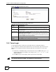
Chapter 14 Dynamic DNS Setup Table 81 Dynamic DNS (continued) LABEL DESCRIPTION Dynamic DNS server auto detect IP Address Select this option only when there are one or more NAT routers between the ZyXEL Device and the DDNS server. This feature has the DDNS server automatically detect and use the IP address of the NAT router that has a public IP address. Note: The DDNS server may not be able to detect the proper IP address if there is an HTTP proxy server between the ZyXEL Device and the DDNS server.
Chapter 14 Dynamic DNS Setup 202 P-660HW-Dx v2 User’s Guide
CHAPTER 15 Remote Management Configuration This chapter provides information on configuring remote management. 15.1 Remote Management Overview Remote management allows you to determine which services/protocols can access which ZyXEL Device interface (if any) from which computers. " When you configure remote management to allow management from the WAN, you still need to configure a firewall rule to allow access.
Chapter 15 Remote Management Configuration 15.1.1 Remote Management Limitations Remote management over LAN or WAN will not work when: • You have disabled that service in one of the remote management screens. • The IP address in the Secured Client IP field does not match the client IP address. If it does not match, the ZyXEL Device will disconnect the session immediately. • There is already another remote management session with an equal or higher priority running.
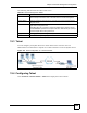
Chapter 15 Remote Management Configuration The following table describes the labels in this screen. Table 82 Remote Management: WWW LABEL DESCRIPTION Port You may change the server port number for a service if needed, however you must use the same port number in order to use that service for remote management. Access Status Select the interface(s) through which a computer may access the ZyXEL Device using this service.
Chapter 15 Remote Management Configuration Figure 117 Remote Management: Telnet The following table describes the labels in this screen. Table 83 Remote Management: Telnet LABEL DESCRIPTION Port You may change the server port number for a service if needed, however you must use the same port number in order to use that service for remote management. Access Status Select the interface(s) through which a computer may access the ZyXEL Device using this service.
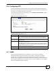
Chapter 15 Remote Management Configuration 15.6 Configuring FTP You can upload and download the ZyXEL Device’s firmware and configuration files using FTP, please see the chapter on firmware and configuration file maintenance for details. To use this feature, your computer must have an FTP client. To change your ZyXEL Device’s FTP settings, click Advanced > Remote MGMT > FTP tab. The screen appears as shown. Figure 118 Remote Management: FTP The following table describes the labels in this screen.
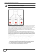
Chapter 15 Remote Management Configuration " SNMP is only available if TCP/IP is configured. Figure 119 SNMP Management Model An SNMP managed network consists of two main types of component: agents and a manager. An agent is a management software module that resides in a managed device (the ZyXEL Device). An agent translates the local management information from the managed device into a form compatible with SNMP.
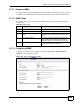
Chapter 15 Remote Management Configuration 15.7.1 Supported MIBs The ZyXEL Device supports MIB II that is defined in RFC-1213 and RFC-1215. The focus of the MIBs is to let administrators collect statistical data and monitor status and performance. 15.7.2 SNMP Traps The ZyXEL Device will send traps to the SNMP manager when any one of the following events occurs: Table 85 SNMP Traps TRAP # TRAP NAME DESCRIPTION 0 coldStart (defined in RFC-1215) A trap is sent after booting (power on).
Chapter 15 Remote Management Configuration The following table describes the labels in this screen. Table 86 Remote Management: SNMP LABEL DESCRIPTION SNMP Port You may change the server port number for a service if needed, however you must use the same port number in order to use that service for remote management. Access Status Select the interface(s) through which a computer may access the ZyXEL Device using this service.
Chapter 15 Remote Management Configuration Figure 121 Remote Management: DNS The following table describes the labels in this screen. Table 87 Remote Management: DNS LABEL DESCRIPTION Port The DNS service port number is 53. Access Status Select the interface(s) through which a computer may send DNS queries to the ZyXEL Device. Secured Client IP A secured client is a “trusted” computer that is allowed to send DNS queries to the ZyXEL Device.
Chapter 15 Remote Management Configuration Figure 122 Remote Management: ICMP The following table describes the labels in this screen. Table 88 Remote Management: ICMP 212 LABEL DESCRIPTION ICMP Internet Control Message Protocol is a message control and error-reporting protocol between a host server and a gateway to the Internet. ICMP uses Internet Protocol (IP) datagrams, but the messages are processed by the TCP/IP software and directly apparent to the application user.
CHAPTER 16 Universal Plug-and-Play (UPnP) This chapter introduces the UPnP feature in the web configurator. 16.1 Introducing Universal Plug and Play Universal Plug and Play (UPnP) is a distributed, open networking standard that uses TCP/IP for simple peer-to-peer network connectivity between devices. A UPnP device can dynamically join a network, obtain an IP address, convey its capabilities and learn about other devices on the network.
Chapter 16 Universal Plug-and-Play (UPnP) When a UPnP device joins a network, it announces its presence with a multicast message. For security reasons, the ZyXEL Device allows multicast messages only on the LAN. All UPnP-enabled devices may communicate freely with each other without additional configuration. Disable UPnP if this is not your intention. You must have IIS (Internet Information Services) enabled on the Windows web server for UPnP to work. 16.
Chapter 16 Universal Plug-and-Play (UPnP) Table 89 Configuring UPnP LABEL DESCRIPTION Allow UPnP to pass through Firewall Select this check box to allow traffic from UPnP-enabled applications to bypass the firewall. Clear this check box to have the firewall block all UPnP application packets (for example, MSN packets). Apply Click Apply to save the setting to the ZyXEL Device. Cancel Click Cancel to return to the previously saved settings. 16.
Chapter 16 Universal Plug-and-Play (UPnP) Figure 125 Add/Remove Programs: Windows Setup: Communication: Components 4 Click OK to go back to the Add/Remove Programs Properties window and click Next. 5 Restart the computer when prompted. 16.3.2 Installing UPnP in Windows XP Follow the steps below to install the UPnP in Windows XP. 1 Click start and Control Panel. 2 Double-click Network Connections.
Chapter 16 Universal Plug-and-Play (UPnP) Figure 127 Windows Optional Networking Components Wizard 5 In the Networking Services window, select the Universal Plug and Play check box. Figure 128 Networking Services 6 Click OK to go back to the Windows Optional Networking Component Wizard window and click Next. 16.4 Using UPnP in Windows XP Example This section shows you how to use the UPnP feature in Windows XP. You must already have UPnP installed in Windows XP and UPnP activated on the ZyXEL Device.
Chapter 16 Universal Plug-and-Play (UPnP) Make sure the computer is connected to a LAN port of the ZyXEL Device. Turn on your computer and the ZyXEL Device. 16.4.1 Auto-discover Your UPnP-enabled Network Device 1 Click start and Control Panel. Double-click Network Connections. An icon displays under Internet Gateway. 2 Right-click the icon and select Properties.
Chapter 16 Universal Plug-and-Play (UPnP) Figure 130 Internet Connection Properties 4 You may edit or delete the port mappings or click Add to manually add port mappings.
Chapter 16 Universal Plug-and-Play (UPnP) Figure 132 Internet Connection Properties: Advanced Settings: Add " When the UPnP-enabled device is disconnected from your computer, all port mappings will be deleted automatically. 5 Select Show icon in notification area when connected option and click OK. An icon displays in the system tray. Figure 133 System Tray Icon 6 Double-click on the icon to display your current Internet connection status.
Chapter 16 Universal Plug-and-Play (UPnP) Figure 134 Internet Connection Status 16.4.2 Web Configurator Easy Access With UPnP, you can access the web-based configurator on the ZyXEL Device without finding out the IP address of the ZyXEL Device first. This comes helpful if you do not know the IP address of the ZyXEL Device. Follow the steps below to access the web configurator. 1 Click Start and then Control Panel. 2 Double-click Network Connections. 3 Select My Network Places under Other Places.
Chapter 16 Universal Plug-and-Play (UPnP) Figure 135 Network Connections 4 An icon with the description for each UPnP-enabled device displays under Local Network. 5 Right-click on the icon for your ZyXEL Device and select Invoke. The web configurator login screen displays.
Chapter 16 Universal Plug-and-Play (UPnP) Figure 136 Network Connections: My Network Places 6 Right-click on the icon for your ZyXEL Device and select Properties. A properties window displays with basic information about the ZyXEL Device.
Chapter 16 Universal Plug-and-Play (UPnP) 224 P-660HW-Dx v2 User’s Guide
P ART VI Maintenance and Troubleshooting System (227) Logs (233) Tools (251) Diagnostic (257) Troubleshooting (259) 225
226
CHAPTER 17 System Use this screen to configure the ZyXEL Device’s time and date settings. 17.1 General Setup 17.1.1 General Setup and System Name General Setup contains administrative and system-related information. System Name is for identification purposes. However, because some ISPs check this name you should enter your computer's "Computer Name". • In Windows 95/98 click Start, Settings, Control Panel, Network.
Chapter 17 System Figure 138 System General Setup The following table describes the labels in this screen. Table 90 System General Setup LABEL DESCRIPTION General Setup System Name Choose a descriptive name for identification purposes. It is recommended you enter your computer’s “Computer name” in this field. This name can be up to 30 alphanumeric characters long. Spaces are not allowed, but dashes “-” and underscores "_" are accepted. Domain Name Enter the domain name (if you know it) here.
Chapter 17 System Table 90 System General Setup LABEL DESCRIPTION Old Password Type the default admin password (1234) or the existing password you use to access the system for configuring advanced features. New Password Type your new system password (up to 30 characters). Note that as you type a password, the screen displays a (*) for each character you type. After you change the password, use the new password to access the ZyXEL Device. Retype to Confirm Type the new password again for confirmation.
Chapter 17 System The following table describes the fields in this screen. Table 91 System Time Setting LABEL DESCRIPTION Current Time and Date Current Time This field displays the time of your ZyXEL Device. Each time you reload this page, the ZyXEL Device synchronizes the time with the time server. Current Date This field displays the date of your ZyXEL Device. Each time you reload this page, the ZyXEL Device synchronizes the date with the time server.
Chapter 17 System Table 91 System Time Setting (continued) LABEL DESCRIPTION Start Date Configure the day and time when Daylight Saving Time starts if you selected Enable Daylight Saving. The o'clock field uses the 24 hour format. Here are a couple of examples: Daylight Saving Time starts in most parts of the United States on the first Sunday of April. Each time zone in the United States starts using Daylight Saving Time at 2 A.M. local time.
Chapter 17 System 232 P-660HW-Dx v2 User’s Guide
CHAPTER 18 Logs This chapter contains information about configuring general log settings and viewing the ZyXEL Device’s logs. Refer to the appendix for example log message explanations. 18.1 Logs Overview The web configurator allows you to choose which categories of events and/or alerts to have the ZyXEL Device log and then display the logs or have the ZyXEL Device send them to an administrator (as e-mail) or to a syslog server. 18.1.
Chapter 18 Logs Figure 140 View Log The following table describes the fields in this screen. Table 92 View Log LABEL DESCRIPTION Display The categories that you select in the Log Settings screen display in the drop-down list box. Select a category of logs to view; select All Logs to view logs from all of the log categories that you selected in the Log Settings page.
Chapter 18 Logs Figure 141 Log Settings The following table describes the fields in this screen. Table 93 Log Settings LABEL DESCRIPTION E-mail Log Settings Mail Server Enter the server name or the IP address of the mail server for the e-mail addresses specified below. If this field is left blank, logs and alert messages will not be sent via E-mail. Mail Subject Type a title that you want to be in the subject line of the log e-mail message that the ZyXEL Device sends.
Chapter 18 Logs Table 93 Log Settings LABEL DESCRIPTION Enable SMTP Authentication Select this option if your mail service requires a user name and password to use email. User Name This is the user name required to access your mail server. Password This is the password name required to access your mail server. Log Schedule This drop-down menu is used to configure the frequency of log messages being sent as E-mail: • Daily • Weekly • Hourly • When Log is Full • None.
Chapter 18 Logs Figure 142 E-mail Log Example Subject: Firewall Alert From xxxxx Date: Fri, 07 Apr 2000 10:05:42 From: user@zyxel.com To: user@zyxel.com 1|Apr 7 00 |From:192.168.1.1 To:192.168.1.255 |default policy |forward | 09:54:03 |UDP src port:00520 dest port:00520 |<1,00> | 2|Apr 7 00 |From:192.168.1.131 To:192.168.1.255 |default policy |forward | 09:54:17 |UDP src port:00520 dest port:00520 |<1,00> | 3|Apr 7 00 |From:192.168.1.6 To:10.10.10.
Chapter 18 Logs Table 94 System Maintenance Logs (continued) LOG MESSAGE DESCRIPTION Starting Connectivity Monitor Starting Connectivity Monitor. Time initialized by Daytime Server The router got the time and date from the Daytime server. Time initialized by Time server The router got the time and date from the time server. Time initialized by NTP server The router got the time and date from the NTP server. Connect to Daytime server fail The router was not able to connect to the Daytime server.
Chapter 18 Logs Table 96 Access Control Logs (continued) LOG MESSAGE DESCRIPTION Triangle route packet forwarded: [TCP | UDP | IGMP | ESP | GRE | OSPF] The firewall allowed a triangle route session to pass through. Packet without a NAT table entry blocked: [TCP | UDP | IGMP | ESP | GRE | OSPF] The router blocked a packet that didn't have a corresponding NAT table entry.
Chapter 18 Logs Table 99 ICMP Logs LOG MESSAGE DESCRIPTION Firewall default policy: ICMP , , ICMP access matched the default policy and was blocked or forwarded according to the user's setting. For type and code details, see Table 110 on page 248. Firewall rule [NOT] match: ICMP , , , ICMP access matched (or didn’t match) a firewall rule (denoted by its number) and was blocked or forwarded according to the rule.
Chapter 18 Logs Table 102 UPnP Logs LOG MESSAGE DESCRIPTION UPnP pass through Firewall UPnP packets can pass through the firewall. Table 103 Content Filtering Logs LOG MESSAGE DESCRIPTION %s: Keyword blocking The content of a requested web page matched a user defined keyword. %s: Not in trusted web list The web site is not in a trusted domain, and the router blocks all traffic except trusted domain sites. %s: Forbidden Web site The web site is in the forbidden web site list.
Chapter 18 Logs Table 104 Attack Logs LOG MESSAGE DESCRIPTION attack [TCP | UDP | IGMP | ESP | GRE | OSPF] The firewall detected a TCP/UDP/IGMP/ESP/GRE/OSPF attack. attack ICMP (type:%d, code:%d) The firewall detected an ICMP attack. For type and code details, see Table 110 on page 248. land [TCP | UDP | IGMP | ESP | GRE | OSPF] The firewall detected a TCP/UDP/IGMP/ESP/GRE/OSPF land attack. land ICMP (type:%d, code:%d) The firewall detected an ICMP land attack.
Chapter 18 Logs Table 105 IPSec Logs (continued) LOG MESSAGE DESCRIPTION Rule <%d> idle time out, disconnect The router dropped a connection that had outbound traffic and no inbound traffic for a certain time period. You can use the "ipsec timer chk_conn" CI command to set the time period. The default value is 2 minutes. WAN IP changed to The router dropped all connections with the “MyIP” configured as “0.0.0.0” when the WAN IP address changed.
Chapter 18 Logs Table 106 IKE Logs (continued) 244 LOG MESSAGE DESCRIPTION Recv IKE uses ISAKMP to transmit data. Each ISAKMP packet contains many different types of payloads. All of them show in the LOG. Refer to RFC2408 – ISAKMP for a list of all ISAKMP payload types. Recv Mode request from The router received an IKE negotiation request from the peer address specified. Send Mode request to The router started negotiation with the peer.
Chapter 18 Logs Table 106 IKE Logs (continued) LOG MESSAGE DESCRIPTION Rule [%d] Phase 1 authentication method mismatch The listed rule’s IKE phase 1 authentication method did not match between the router and the peer. Rule [%d] Phase 1 key group mismatch The listed rule’s IKE phase 1 key group did not match between the router and the peer. Rule [%d] Phase 2 protocol mismatch The listed rule’s IKE phase 2 protocol did not match between the router and the peer.
Chapter 18 Logs Table 107 PKI Logs 246 LOG MESSAGE DESCRIPTION Enrollment successful The SCEP online certificate enrollment was successful. The Destination field records the certification authority server IP address and port. Enrollment failed The SCEP online certificate enrollment failed. The Destination field records the certification authority server’s IP address and port.
Chapter 18 Logs Table 108 Certificate Path Verification Failure Reason Codes CODE DESCRIPTION 1 Algorithm mismatch between the certificate and the search constraints. 2 Key usage mismatch between the certificate and the search constraints. 3 Certificate was not valid in the time interval. 4 (Not used) 5 Certificate is not valid. 6 Certificate signature was not verified correctly. 7 Certificate was revoked by a CRL. 8 Certificate was not added to the cache. 9 Certificate decoding failed.
Chapter 18 Logs Table 110 ICMP Notes TYPE CODE Echo Reply 0 0 Echo reply message Destination Unreachable 3 0 Net unreachable 1 Host unreachable 2 Protocol unreachable 3 Port unreachable 4 A packet that needed fragmentation was dropped because it was set to Don't Fragment (DF) 5 Source route failed Source Quench 4 0 A gateway may discard internet datagrams if it does not have the buffer space needed to queue the datagrams for output to the next network on the route to the destination netwo
Chapter 18 Logs Table 111 Syslog Logs LOG MESSAGE DESCRIPTION Mon dd hr:mm:ss hostname src="" dst="" msg="" note="" devID="" cat=" "This message is sent by the system ("RAS" displays as the system name if you haven’t configured one) when the router generates a syslog. The facility is defined in the web MAIN MENU->LOGS->Log Settings page. The severity is the log’s syslog class.
Chapter 18 Logs 250 P-660HW-Dx v2 User’s Guide
CHAPTER 19 Tools This chapter describes how to upload new firmware, manage configuration and restart your ZyXEL Device. 19.1 Firmware Upgrade Find firmware at www.zyxel.com in a file that (usually) uses the system model name with a .bin extension, for example, "ZyXEL Device.bin". The upload process uses HTTP (Hypertext Transfer Protocol) and may take up to two minutes. After a successful upload, the system will reboot. Only use firmware for your device’s specific model.
Chapter 19 Tools The following table describes the labels in this screen. Table 113 Firmware Upgrade 1 LABEL DESCRIPTION Current Firmware Version This is the present Firmware version and the date created. File Path Type in the location of the file you want to upload in this field or click Browse ... to find it. Browse... Click Browse... to find the .bin file you want to upload. Remember that you must decompress compressed (.zip) files before you can upload them.
Chapter 19 Tools Figure 146 Error Message 19.2 Configuration Screen Click Maintenance > Tools > Configuration. Information related to factory defaults, backup configuration, and restoring configuration appears as shown next. Figure 147 Configuration 19.2.1 Backup Configuration Backup configuration allows you to back up (save) the ZyXEL Device’s current configuration to a file on your computer.
Chapter 19 Tools 19.2.2 Restore Configuration Restore configuration allows you to upload a new or previously saved configuration file from your computer to your ZyXEL Device. Table 114 Maintenance Restore Configuration 1 LABEL DESCRIPTION File Path Type in the location of the file you want to upload in this field or click Browse... to find it. Browse... Click Browse... to find the file you want to upload. Remember that you must decompress compressed (.ZIP) files before you can upload them.
Chapter 19 Tools Figure 150 Configuration Restore Error 19.2.3 Back to Factory Defaults Pressing the RESET button in this section clears all user-entered configuration information and returns the ZyXEL Device to its factory defaults. You can also press the RESET button on the rear panel to reset the factory defaults of your ZyXEL Device. Refer to the chapter about introducing the web configurator for more information on the RESET button. 19.
Chapter 19 Tools 256 P-660HW-Dx v2 User’s Guide
CHAPTER 20 Diagnostic These read-only screens display information to help you identify problems with the ZyXEL Device. 20.1 General Diagnostic Click Maintenance > Diagnostic to open the screen shown next. Figure 152 Diagnostic: General The following table describes the fields in this screen. Table 115 Diagnostic: General LABEL DESCRIPTION TCP/IP Address Type the IP address of a computer that you want to ping in order to test a connection.
Chapter 20 Diagnostic Figure 153 Diagnostic: DSL Line The following table describes the fields in this screen. Table 116 Diagnostic: DSL Line LABEL DESCRIPTION ATM Status Click this button to view ATM status. ATM Loopback Test Click this button to start the ATM loopback test. Make sure you have configured at least one PVC with proper VPIs/VCIs before you begin this test. The ZyXEL Device sends an OAM F5 packet to the DSLAM/ATM switch and then returns it (loops it back) to the ZyXEL Device.
CHAPTER 21 Troubleshooting This chapter offers some suggestions to solve problems you might encounter. The potential problems are divided into the following categories. • Power, Hardware Connections, and LEDs • ZyXEL Device Access and Login • Internet Access 21.1 Power, Hardware Connections, and LEDs V The ZyXEL Device does not turn on. None of the LEDs turn on. 1 Make sure the ZyXEL Device is turned on. 2 Make sure you are using the power adaptor or cord included with the ZyXEL Device.
Chapter 21 Troubleshooting 21.2 ZyXEL Device Access and Login V I forgot the IP address for the ZyXEL Device. • The default IP address is 192.168.1.1. 6 If you changed the IP address and have forgotten it, you might get the IP address of the ZyXEL Device by looking up the IP address of the default gateway for your computer. To do this in most Windows computers, click Start > Run, enter cmd, and then enter ipconfig.
Chapter 21 Troubleshooting 5 Reset the device to its factory defaults, and try to access the ZyXEL Device with the default IP address. See Section 2.3 on page 42. 6 If the problem continues, contact the network administrator or vendor, or try one of the advanced suggestions. Advanced Suggestions • Try to access the ZyXEL Device using another service, such as Telnet.
Chapter 21 Troubleshooting 1 Check the hardware connections, and make sure the LEDs are behaving as expected. See the Quick Start Guide and Section 1.4 on page 35. 2 If your ISP gave you Internet connection information, make sure you entered it correctly in the Network > WAN > Internet Connection screen. These fields are case-sensitive, so make sure [Caps Lock] is not on.
P ART VII Appendices and Index Product Specifications and Wall Mounting (265) Wireless LANs (271) Setting up Your Computer’s IP Address (285) IP Addresses and Subnetting (301) Firewall Commands (311) Internal SPTGEN (317) Command Interpreter (331) Pop-up Windows, JavaScripts and Java Permissions (333) NetBIOS Filter Commands (339) Splitters and Microfilters (341) Triangle Route (341) Legal Information (343) Customer Support (347) Index (351) 263
264
APPENDIX A Product Specifications and Wall Mounting Product Specifications The following tables summarize the ZyXEL Device’s hardware and firmware features.
Appendix A Product Specifications and Wall Mounting Table 118 Firmware Specifications 266 FEATURE DESCRIPTION Configuration Backup & Restoration Make a copy of the ZyXEL Device’s configuration. You can put it back on the ZyXEL Device later if you decide to revert back to an earlier configuration. Network Address Translation (NAT) Each computer on your network must have its own unique IP address.
Appendix A Product Specifications and Wall Mounting Table 118 Firmware Specifications FEATURE DESCRIPTION Any IP The Any IP feature allows one computer to connect to the ZyXEL Device (and then to other computers) when their IP addresses are in different subnets. This is done without changing the network settings (such as IP address and subnet mask) of the computer.
Appendix A Product Specifications and Wall Mounting Table 120 Standards Supported (continued) 268 STANDARD DESCRIPTION RFC 1305 Network Time Protocol (NTP version 3) RFC 1441 SNMPv2 Simple Network Management Protocol version 2 RFC 1483 Multiprotocol Encapsulation over ATM Adaptation Layer 5 RFC 1631 IP Network Address Translator (NAT) RFC 1661 The Point-to-Point Protocol (PPP) RFC 1723 RIP-2 (Routing Information Protocol) RFC 1901 SNMPv2c Simple Network Management Protocol version 2c RFC 2
Appendix A Product Specifications and Wall Mounting Wall-mounting Instructions Complete the following steps to hang your ZyXEL Device on a wall. " See the Hardware Specifications table for the size of screws to use and how far apart to place them. 1 Select a high position on a sturdy wall that is free of obstructions. 2 Drill two holes for the screws. 3 Be careful to avoid damaging pipes or cables located inside the wall when drilling holes for the screws.
Appendix A Product Specifications and Wall Mounting Figure 155 Masonry Plug and M4 Tap Screw 270 P-660HW-Dx v2 User’s Guide
APPENDIX B Wireless LANs Wireless LAN Topologies This section discusses ad-hoc and infrastructure wireless LAN topologies. Ad-hoc Wireless LAN Configuration The simplest WLAN configuration is an independent (Ad-hoc) WLAN that connects a set of computers with wireless adapters (A, B, C). Any time two or more wireless adapters are within range of each other, they can set up an independent network, which is commonly referred to as an ad-hoc network or Independent Basic Service Set (IBSS).
Appendix B Wireless LANs Figure 157 Basic Service Set ESS An Extended Service Set (ESS) consists of a series of overlapping BSSs, each containing an access point, with each access point connected together by a wired network. This wired connection between APs is called a Distribution System (DS). This type of wireless LAN topology is called an Infrastructure WLAN. The Access Points not only provide communication with the wired network but also mediate wireless network traffic in the immediate neighborhood.
Appendix B Wireless LANs Figure 158 Infrastructure WLAN Channel A channel is the radio frequency(ies) used by wireless devices to transmit and receive data. Channels available depend on your geographical area. You may have a choice of channels (for your region) so you should use a channel different from an adjacent AP (access point) to reduce interference. Interference occurs when radio signals from different access points overlap causing interference and degrading performance.
Appendix B Wireless LANs Figure 159 RTS/CTS When station A sends data to the AP, it might not know that the station B is already using the channel. If these two stations send data at the same time, collisions may occur when both sets of data arrive at the AP at the same time, resulting in a loss of messages for both stations. RTS/CTS is designed to prevent collisions due to hidden nodes.
Appendix B Wireless LANs If the Fragmentation Threshold value is smaller than the RTS/CTS value (see previously) you set then the RTS (Request To Send)/CTS (Clear to Send) handshake will never occur as data frames will be fragmented before they reach RTS/CTS size. Preamble Type Preamble is used to signal that data is coming to the receiver. Short and long refer to the length of the synchronization field in a packet.
Appendix B Wireless LANs Wireless security methods available on the ZyXEL Device are data encryption, wireless client authentication, restricting access by device MAC address and hiding the ZyXEL Device identity. The following figure shows the relative effectiveness of these wireless security methods available on your ZyXEL Device.
Appendix B Wireless LANs Determines the network services available to authenticated users once they are connected to the network. • Accounting Keeps track of the client’s network activity. RADIUS is a simple package exchange in which your AP acts as a message relay between the wireless client and the network RADIUS server.
Appendix B Wireless LANs For EAP-TLS authentication type, you must first have a wired connection to the network and obtain the certificate(s) from a certificate authority (CA). A certificate (also called digital IDs) can be used to authenticate users and a CA issues certificates and guarantees the identity of each certificate owner. EAP-MD5 (Message-Digest Algorithm 5) MD5 authentication is the simplest one-way authentication method. The authentication server sends a challenge to the wireless client.
Appendix B Wireless LANs Dynamic WEP Key Exchange The AP maps a unique key that is generated with the RADIUS server. This key expires when the wireless connection times out, disconnects or reauthentication times out. A new WEP key is generated each time reauthentication is performed. If this feature is enabled, it is not necessary to configure a default encryption key in the wireless security configuration screen.
Appendix B Wireless LANs Encryption Both WPA and WPA2 improve data encryption by using Temporal Key Integrity Protocol (TKIP), Message Integrity Check (MIC) and IEEE 802.1x. WPA and WPA2 use Advanced Encryption Standard (AES) in the Counter mode with Cipher block chaining Message authentication code Protocol (CCMP) to offer stronger encryption than TKIP. TKIP uses 128-bit keys that are dynamically generated and distributed by the authentication server.
Appendix B Wireless LANs Wireless Client WPA Supplicants A wireless client supplicant is the software that runs on an operating system instructing the wireless client how to use WPA. At the time of writing, the most widely available supplicant is the WPA patch for Windows XP, Funk Software's Odyssey client. The Windows XP patch is a free download that adds WPA capability to Windows XP's builtin "Zero Configuration" wireless client. However, you must run Windows XP to use it.
Appendix B Wireless LANs 3 The AP and wireless clients generate a common PMK (Pairwise Master Key). The key itself is not sent over the network, but is derived from the PSK and the SSID. 4 The AP and wireless clients use the TKIP or AES encryption process, the PMK and information exchanged in a handshake to create temporal encryption keys. They use these keys to encrypt data exchanged between them.
Appendix B Wireless LANs Antenna Overview An antenna couples RF signals onto air. A transmitter within a wireless device sends an RF signal to the antenna, which propagates the signal through the air. The antenna also operates in reverse by capturing RF signals from the air. Positioning the antennas properly increases the range and coverage area of a wireless LAN. Antenna Characteristics Frequency An antenna in the frequency of 2.4GHz (IEEE 802.11b and IEEE 802.11g) or 5GHz (IEEE 802.
Appendix B Wireless LANs Positioning Antennas In general, antennas should be mounted as high as practically possible and free of obstructions. In point-to–point application, position both antennas at the same height and in a direct line of sight to each other to attain the best performance. For omni-directional antennas mounted on a table, desk, and so on, point the antenna up. For omni-directional antennas mounted on a wall or ceiling, point the antenna down.
APPENDIX C Setting up Your Computer’s IP Address All computers must have a 10M or 100M Ethernet adapter card and TCP/IP installed. Windows 95/98/Me/NT/2000/XP, Macintosh OS 7 and later operating systems and all versions of UNIX/LINUX include the software components you need to install and use TCP/ IP on your computer. Windows 3.1 requires the purchase of a third-party TCP/IP application package.
Appendix C Setting up Your Computer’s IP Address Figure 162 WIndows 95/98/Me: Network: Configuration Installing Components The Network window Configuration tab displays a list of installed components. You need a network adapter, the TCP/IP protocol and Client for Microsoft Networks. If you need the adapter: 1 In the Network window, click Add. 2 Select Adapter and then click Add. 3 Select the manufacturer and model of your network adapter and then click OK.
Appendix C Setting up Your Computer’s IP Address Configuring 1 In the Network window Configuration tab, select your network adapter's TCP/IP entry and click Properties 2 Click the IP Address tab. • If your IP address is dynamic, select Obtain an IP address automatically. • If you have a static IP address, select Specify an IP address and type your information into the IP Address and Subnet Mask fields. Figure 163 Windows 95/98/Me: TCP/IP Properties: IP Address 3 Click the DNS Configuration tab.
Appendix C Setting up Your Computer’s IP Address Figure 164 Windows 95/98/Me: TCP/IP Properties: DNS Configuration 4 Click the Gateway tab. • If you do not know your gateway’s IP address, remove previously installed gateways. • If you have a gateway IP address, type it in the New gateway field and click Add. 5 Click OK to save and close the TCP/IP Properties window. 6 Click OK to close the Network window. Insert the Windows CD if prompted.
Appendix C Setting up Your Computer’s IP Address Figure 165 Windows XP: Start Menu 2 In the Control Panel, double-click Network Connections (Network and Dial-up Connections in Windows 2000/NT). Figure 166 Windows XP: Control Panel 3 Right-click Local Area Connection and then click Properties.
Appendix C Setting up Your Computer’s IP Address Figure 167 Windows XP: Control Panel: Network Connections: Properties 4 Select Internet Protocol (TCP/IP) (under the General tab in Win XP) and then click Properties. Figure 168 Windows XP: Local Area Connection Properties 5 The Internet Protocol TCP/IP Properties window opens (the General tab in Windows XP). • If you have a dynamic IP address click Obtain an IP address automatically.
Appendix C Setting up Your Computer’s IP Address Figure 169 Windows XP: Internet Protocol (TCP/IP) Properties 6 If you do not know your gateway's IP address, remove any previously installed gateways in the IP Settings tab and click OK. Do one or more of the following if you want to configure additional IP addresses: • In the IP Settings tab, in IP addresses, click Add. • In TCP/IP Address, type an IP address in IP address and a subnet mask in Subnet mask, and then click Add.
Appendix C Setting up Your Computer’s IP Address Figure 170 Windows XP: Advanced TCP/IP Properties 7 In the Internet Protocol TCP/IP Properties window (the General tab in Windows XP): • Click Obtain DNS server address automatically if you do not know your DNS server IP address(es). • If you know your DNS server IP address(es), click Use the following DNS server addresses, and type them in the Preferred DNS server and Alternate DNS server fields.
Appendix C Setting up Your Computer’s IP Address Figure 171 Windows XP: Internet Protocol (TCP/IP) Properties 8 Click OK to close the Internet Protocol (TCP/IP) Properties window. 9 Click Close (OK in Windows 2000/NT) to close the Local Area Connection Properties window. 10 Close the Network Connections window (Network and Dial-up Connections in Windows 2000/NT). 11 Turn on your ZyXEL Device and restart your computer (if prompted).
Appendix C Setting up Your Computer’s IP Address Figure 172 Macintosh OS 8/9: Apple Menu 2 Select Ethernet built-in from the Connect via list. Figure 173 Macintosh OS 8/9: TCP/IP 3 For dynamically assigned settings, select Using DHCP Server from the Configure: list. 4 For statically assigned settings, do the following: • From the Configure box, select Manually.
Appendix C Setting up Your Computer’s IP Address • Type your IP address in the IP Address box. • Type your subnet mask in the Subnet mask box. • Type the IP address of your ZyXEL Device in the Router address box. 5 Close the TCP/IP Control Panel. 6 Click Save if prompted, to save changes to your configuration. 7 Turn on your ZyXEL Device and restart your computer (if prompted). Verifying Settings Check your TCP/IP properties in the TCP/IP Control Panel window.
Appendix C Setting up Your Computer’s IP Address Figure 175 Macintosh OS X: Network 4 For statically assigned settings, do the following: • From the Configure box, select Manually. • Type your IP address in the IP Address box. • Type your subnet mask in the Subnet mask box. • Type the IP address of your ZyXEL Device in the Router address box. 5 Click Apply Now and close the window. 6 Turn on your ZyXEL Device and restart your computer (if prompted).
Appendix C Setting up Your Computer’s IP Address " Make sure you are logged in as the root administrator. Using the K Desktop Environment (KDE) Follow the steps below to configure your computer IP address using the KDE. 1 Click the Red Hat button (located on the bottom left corner), select System Setting and click Network. Figure 176 Red Hat 9.0: KDE: Network Configuration: Devices 2 Double-click on the profile of the network card you wish to configure.
Appendix C Setting up Your Computer’s IP Address • If you have a dynamic IP address click Automatically obtain IP address settings with and select dhcp from the drop down list. • If you have a static IP address click Statically set IP Addresses and fill in the Address, Subnet mask, and Default Gateway Address fields. 3 Click OK to save the changes and close the Ethernet Device General screen. 4 If you know your DNS server IP address(es), click the DNS tab in the Network Configuration screen.
Appendix C Setting up Your Computer’s IP Address Figure 180 Red Hat 9.0: Dynamic IP Address Setting in ifconfig-eth0 DEVICE=eth0 ONBOOT=yes BOOTPROTO=dhcp USERCTL=no PEERDNS=yes TYPE=Ethernet • If you have a static IP address, enter static in the BOOTPROTO= field. Type IPADDR= followed by the IP address (in dotted decimal notation) and type NETMASK= followed by the subnet mask. The following example shows an example where the static IP address is 192.168.1.10 and the subnet mask is 255.255.255.0.
Appendix C Setting up Your Computer’s IP Address Verifying Settings Enter ifconfig in a terminal screen to check your TCP/IP properties. Figure 184 Red Hat 9.0: Checking TCP/IP Properties [root@localhost]# ifconfig eth0 Link encap:Ethernet HWaddr 00:50:BA:72:5B:44 inet addr:172.23.19.129 Bcast:172.23.19.255 Mask:255.255.255.