APPENDIX D IP Addresses and Subnetting This appendix introduces IP addresses and subnet masks. IP addresses identify individual devices on a network. Every networking device (including computers, servers, routers, printers, etc.) needs an IP address to communicate across the network. These networking devices are also known as hosts. Subnet masks determine the maximum number of possible hosts on a network. You can also use subnet masks to divide one network into multiple sub-networks.
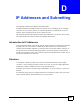
Appendix D IP Addresses and Subnetting Figure 185 Network Number and Host ID How much of the IP address is the network number and how much is the host ID varies according to the subnet mask. Subnet Masks A subnet mask is used to determine which bits are part of the network number, and which bits are part of the host ID (using a logical AND operation). The term “subnet” is short for “subnetwork”. A subnet mask has 32 bits.
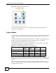
Appendix D IP Addresses and Subnetting Subnet masks are expressed in dotted decimal notation just like IP addresses. The following examples show the binary and decimal notation for 8-bit, 16-bit, 24-bit and 29-bit subnet masks. Table 126 Subnet Masks BINARY DECIMAL 1ST OCTET 2ND OCTET 3RD OCTET 4TH OCTET 8-bit mask 11111111 00000000 00000000 00000000 255.0.0.0 16-bit mask 11111111 11111111 00000000 00000000 255.255.0.0 24-bit mask 11111111 11111111 11111111 00000000 255.255.255.
Appendix D IP Addresses and Subnetting Table 128 Alternative Subnet Mask Notation (continued) SUBNET MASK ALTERNATIVE NOTATION LAST OCTET (BINARY) LAST OCTET (DECIMAL) 255.255.255.192 /26 1100 0000 192 255.255.255.224 /27 1110 0000 224 255.255.255.240 /28 1111 0000 240 255.255.255.248 /29 1111 1000 248 255.255.255.252 /30 1111 1100 252 Subnetting You can use subnetting to divide one network into multiple sub-networks.
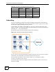
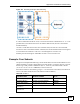
Appendix D IP Addresses and Subnetting Figure 187 Subnetting Example: After Subnetting In a 25-bit subnet the host ID has 7 bits, so each sub-network has a maximum of 27 – 2 or 126 possible hosts (a host ID of all zeroes is the subnet’s address itself, all ones is the subnet’s broadcast address). 192.168.1.0 with mask 255.255.255.128 is subnet A itself, and 192.168.1.127 with mask 255.255.255.128 is its broadcast address.
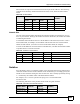
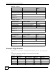
Appendix D IP Addresses and Subnetting Table 130 Subnet 2 IP/SUBNET MASK NETWORK NUMBER LAST OCTET BIT VALUE IP Address 192.168.1. 64 IP Address (Binary) 11000000.10101000.00000001. 01000000 Subnet Mask (Binary) 11111111.11111111.11111111. 11000000 Subnet Address: 192.168.1.64 Lowest Host ID: 192.168.1.65 Broadcast Address: 192.168.1.127 Highest Host ID: 192.168.1.126 Table 131 Subnet 3 IP/SUBNET MASK NETWORK NUMBER LAST OCTET BIT VALUE IP Address 192.168.1.
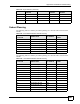
Appendix D IP Addresses and Subnetting Table 133 Eight Subnets (continued) SUBNET SUBNET ADDRESS FIRST ADDRESS LAST ADDRESS BROADCAST ADDRESS 5 128 129 158 159 6 160 161 190 191 7 192 193 222 223 8 224 225 254 255 Subnet Planning The following table is a summary for subnet planning on a network with a 24-bit network number. Table 134 24-bit Network Number Subnet Planning NO. “BORROWED” HOST BITS SUBNET MASK NO. SUBNETS NO. HOSTS PER SUBNET 1 255.255.255.
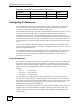
Appendix D IP Addresses and Subnetting Table 135 16-bit Network Number Subnet Planning (continued) NO. “BORROWED” HOST BITS SUBNET MASK NO. SUBNETS NO. HOSTS PER SUBNET 14 255.255.255.252 (/30) 16384 2 15 255.255.255.254 (/31) 32768 1 Configuring IP Addresses Where you obtain your network number depends on your particular situation. If the ISP or your network administrator assigns you a block of registered IP addresses, follow their instructions in selecting the IP addresses and the subnet mask.
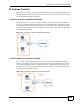
Appendix D IP Addresses and Subnetting IP Address Conflicts Each device on a network must have a unique IP address. Devices with duplicate IP addresses on the same network will not be able to access the Internet or other resources. The devices may also be unreachable through the network. Conflicting Computer IP Addresses Example More than one device can not use the same IP address.
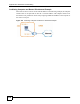
Appendix D IP Addresses and Subnetting Conflicting Computer and Router IP Addresses Example More than one device can not use the same IP address. In the following example, the computer and the router’s LAN port both use 192.168.1.1 as the IP address. The computer cannot access the Internet. This problem can be solved by assigning a different IP address to the computer or the router’s LAN port.
APPENDIX E Firewall Commands The following describes the firewall commands. Table 136 Firewall Commands FUNCTION COMMAND DESCRIPTION config edit firewall active This command turns the firewall on or off. config retrieve firewall This command returns the previously saved firewall settings. config save firewall This command saves the current firewall settings. config display firewall This command shows the of all the firewall settings including e-mail, attack, and the sets/ rules.
Appendix E Firewall Commands Table 136 Firewall Commands (continued) FUNCTION COMMAND DESCRIPTION config edit firewall e-mail mail-server This command sets the IP address to which the e-mail messages are sent. config edit firewall e-mail return-addr This command sets the source e-mail address of the firewall e-mails. config edit firewall e-mail email-to This command sets the e-mail address to which the firewall e-mails are sent.
Appendix E Firewall Commands Table 136 Firewall Commands (continued) FUNCTION Sets COMMAND DESCRIPTION config edit firewall attack minute-high <0-255> This command sets the threshold rate of new half-open sessions per minute where the ZyXEL Device starts deleting old half-opened sessions until it gets them down to the minute-low threshold. config edit firewall attack minute-low <0-255> This command sets the threshold of half-open sessions where the ZyXEL Device stops deleting half-opened sessions.
Appendix E Firewall Commands Table 136 Firewall Commands (continued) FUNCTION Rules 314 COMMAND DESCRIPTION Config edit firewall set tcp-idle-timeout This command sets how long ZyXEL Device lets an inactive TCP connection remain open before considering it closed. Config edit firewall set log This command sets whether or not the ZyXEL Device creates logs for packets that match the firewall’s default rule set.
Appendix E Firewall Commands Table 136 Firewall Commands (continued) FUNCTION COMMAND DESCRIPTION config edit firewall set rule destaddrsingle This command sets the rule to have the ZyXEL Device check for traffic with this individual destination address.
Appendix E Firewall Commands Table 136 Firewall Commands (continued) FUNCTION 316 COMMAND DESCRIPTION config delete firewall set rule This command removes the specified rule in a firewall configuration set.
APPENDIX F Internal SPTGEN This appendix introduces Internal SPTGEN. All menus shown in this appendix are example menus meant to show SPTGEN usage. Actual menus for your product may differ. Internal SPTGEN Overview Internal SPTGEN (System Parameter Table Generator) is a configuration text file useful for efficient configuration of multiple ZyXEL Devices.
Appendix F Internal SPTGEN " DO NOT alter or delete any field except parameters in the Input column. This appendix introduces Internal SPTGEN. All menus shown in this appendix are example menus meant to show SPTGEN usage. Actual menus for your product may differ. Internal SPTGEN File Modification - Important Points to Remember Each parameter you enter must be preceded by one “=”sign and one space. Some parameters are dependent on others.
Appendix F Internal SPTGEN Figure 194 Internal SPTGEN FTP Download Example c:\ftp 192.168.1.1 220 PPP FTP version 1.0 ready at Sat Jan 1 03:22:12 2000 User (192.168.1.1:(none)): 331 Enter PASS command Password: 230 Logged in ftp>bin 200 Type I OK ftp> get rom-t ftp>bye c:\edit rom-t (edit the rom-t text file by a text editor and save it) " You can rename your “rom-t” file when you save it to your computer but it must be named “rom-t” when you upload it to your ZyXEL Device.
Appendix F Internal SPTGEN Example Internal SPTGEN Menus This section provides example Internal SPTGEN menus. Table 137 Abbreviations Used in the Example Internal SPTGEN Screens Table ABBREVIATION MEANING FIN Field Identification Number FN Field Name PVA Parameter Values Allowed INPUT An example of what you may enter * Applies to the ZyXEL Device.
Appendix F Internal SPTGEN Table 139 Menu 3 / Menu 3.2 TCP/IP and DHCP Ethernet Setup FIN FN PVA INPUT 30200001 = DHCP <0(None) | 1(Server) | 2(Relay)> = 0 30200002 = Client IP Pool Starting Address = 192.168.1.33 30200003 = Size of Client IP Pool = 32 30200004 = Primary DNS Server = 0.0.0.0 30200005 = Secondary DNS Server = 0.0.0.0 30200006 = Remote DHCP Server = 0.0.0.0 30200008 = IP Address = 172.21.2.
Appendix F Internal SPTGEN Table 139 Menu 3 30201008 = IP Alias #1 Incoming protocol filters Set 3 = 256 30201009 = IP Alias #1 Incoming protocol filters Set 4 = 256 30201010 = IP Alias #1 Outgoing protocol filters Set 1 = 256 30201011 = IP Alias #1 Outgoing protocol filters Set 2 = 256 30201012 = IP Alias #1 Outgoing protocol filters Set 3 = 256 30201013 = IP Alias #1 Outgoing protocol filters Set 4 = 256 30201014 = IP Alias 2 <0(No) | 1(Yes)> = 0 30201015 = IP Address = 0.0.0.
Appendix F Internal SPTGEN Table 140 Menu 4 Internet Access Setup (continued) 40000001 = ISP <0(No) | 1(Yes)> = 1 40000002 = Active <0(No) | 1(Yes)> = 1 40000003 = ISP's Name 40000004 = Encapsulation <2(PPPOE) | 3(RFC 1483)| 4(PPPoA )| 5(ENET ENCAP)> = 2 40000005 = Multiplexing <1(LLC-based) | 2(VC-based) = 1 40000006 = VPI # = 0 40000007 = VCI # = 35 40000008 = Service Name = any 40000009 = My Login = test@pqa 40000010 = My Password = 1234 40000011 = S
Appendix F Internal SPTGEN Table 140 Menu 4 Internet Access Setup (continued) 40000031= RIP Direction <0(None) | 1(Both) | 2(In Only) | 3(Out Only)> = 0 40000032= RIP Version <0(Rip-1) | 1(Rip-2B) |2(Rip-2M)> = 0 40000033= Nailed-up Connection <0(No) |1(Yes)> = 0 Table 141 Menu 12 / Menu 12.1.
Appendix F Internal SPTGEN Table 142 Menu 15 SUA Server Setup (continued) 150000004 = SUA Server #2 Port Start 150000005 = SUA Server #2 Port End = 0 150000006 = SUA Server #2 Local IP address = 0.0.0.0 150000007 = SUA Server #3 Active <0(No) | 1(Yes)> = 0 150000008 = SUA Server #3 Protocol <0(All)|6(TCP)|17(U DP)> = 0 150000009 = SUA Server #3 Port Start = 0 150000010 = SUA Server #3 Port End = 0 150000011 = SUA Server #3 Local IP address = 0.0.0.
Appendix F Internal SPTGEN Table 142 Menu 15 SUA Server Setup (continued) 150000038 = SUA Server #9 Protocol <0(All)|6(TCP)|17(U DP)> = 0 150000039 = SUA Server #9 Port Start = 0 150000040 = SUA Server #9 Port End = 0 150000041 = SUA Server #9 Local IP address = 0.0.0.
Appendix F Internal SPTGEN Table 143 Menu 21.1 Filter Set #1 (continued) 210101009 = IP Filter Set 1,Rule 1 Src Subnet Mask = 0 210101010 = IP Filter Set 1,Rule 1 Src Port 210101011 = IP Filter Set 1,Rule 1 Src Port Comp <0(none)|1(equal) |2(not equal)|3(less)|4( greater)> = 0 210101013 = IP Filter Set 1,Rule 1 Act Match <1(check next)|2(forward)| 3(drop)> = 3 210101014 = IP Filter Set 1,Rule 1 Act Not Match <1(check next)|2(forward)| 3(drop)> = 1 = 0 / Menu 21.1.1.
Appendix F Internal SPTGEN Table 144 Menu 21.1 Filer Set #2, (continued) FIN FN PVA INPUT 210201001 = IP Filter Set 2, Rule 1 Type <0(none)|2(TCP/ IP)> = 2 210201002 = IP Filter Set 2, Rule 1 Active <0(No)|1(Yes)> = 1 210201003 = IP Filter Set 2, Rule 1 Protocol = 6 210201004 = IP Filter Set 2, Rule 1 Dest IP address = 0.0.0.
Appendix F Internal SPTGEN Table 144 Menu 21.
Appendix F Internal SPTGEN Table 145 Menu 23 System Menus (continued) 230400002 = ReAuthentication Timer (in second) = 555 230400003 = Idle Timeout (in second) = 999 230400004 = Authentication Databases <0(Local User Database Only) |1(RADIUS Only) |2(Local,RADIUS) |3(RADIUS,Local)> = 1 230400005 = Key Management Protocol <0(8021x) |1(WPA) |2(WPAPSK)> = 0 230400006 = Dynamic WEP Key Exchange <0(Disable) |1(64bit WEP) |2(128-bit WEP)> = 0 230400007 = PSK 230400008 = WPA Mixed Mode 230400
Appendix F Internal SPTGEN Command Examples The following are example Internal SPTGEN screens associated with the ZyXEL Device’s command interpreter commands. Table 147 Command Examples FIN FN PVA INPUT /ci command (for annex a): wan adsl opencmd FIN FN PVA INPUT 990000001 = ADSL OPMD <0(glite)|1(t1.
Appendix F Internal SPTGEN 332 P-660HW-Dx v2 User’s Guide
APPENDIX G Pop-up Windows, JavaScripts and Java Permissions In order to use the web configurator you need to allow: • Web browser pop-up windows from your device. • JavaScripts (enabled by default). • Java permissions (enabled by default). " Internet Explorer 6 screens are used here. Screens for other Internet Explorer versions may vary. Internet Explorer Pop-up Blockers You may have to disable pop-up blocking to log into your device.
Appendix G Pop-up Windows, JavaScripts and Java Permissions 2 Clear the Block pop-ups check box in the Pop-up Blocker section of the screen. This disables any web pop-up blockers you may have enabled. Figure 197 Internet Options: Privacy 3 Click Apply to save this setting. Enable pop-up Blockers with Exceptions Alternatively, if you only want to allow pop-up windows from your device, see the following steps. 1 In Internet Explorer, select Tools, Internet Options and then the Privacy tab.
Appendix G Pop-up Windows, JavaScripts and Java Permissions Figure 198 Internet Options: Privacy 3 Type the IP address of your device (the web page that you do not want to have blocked) with the prefix “http://”. For example, http://192.168.167.1. 4 Click Add to move the IP address to the list of Allowed sites.
Appendix G Pop-up Windows, JavaScripts and Java Permissions 5 Click Close to return to the Privacy screen. 6 Click Apply to save this setting. JavaScripts If pages of the web configurator do not display properly in Internet Explorer, check that JavaScripts are allowed. 1 In Internet Explorer, click Tools, Internet Options and then the Security tab. Figure 200 Internet Options: Security 2 3 4 5 6 336 Click the Custom Level... button. Scroll down to Scripting.
Appendix G Pop-up Windows, JavaScripts and Java Permissions Figure 201 Security Settings - Java Scripting Java Permissions 1 2 3 4 5 From Internet Explorer, click Tools, Internet Options and then the Security tab. Click the Custom Level... button. Scroll down to Microsoft VM. Under Java permissions make sure that a safety level is selected. Click OK to close the window.
Appendix G Pop-up Windows, JavaScripts and Java Permissions JAVA (Sun) 1 From Internet Explorer, click Tools, Internet Options and then the Advanced tab. 2 Make sure that Use Java 2 for
APPENDIX H NetBIOS Filter Commands The following describes the NetBIOS packet filter commands. Introduction NetBIOS (Network Basic Input/Output System) are TCP or UDP broadcast packets that enable a computer to connect to and communicate with a LAN. For some dial-up services such as PPPoE or PPTP, NetBIOS packets cause unwanted calls. You can configure NetBIOS filters to do the following: • Allow or disallow the sending of NetBIOS packets from the LAN to the WAN and from the WAN to the LAN.
Appendix H NetBIOS Filter Commands The filter types and their default settings are as follows. Table 148 NetBIOS Filter Default Settings NAME DESCRIPTION EXAMPLE Between LAN and WAN This field displays whether NetBIOS packets are blocked or forwarded between the LAN and the WAN. Block IPSec Packets This field displays whether NetBIOS packets sent through a VPN connection are blocked or forwarded.
APPENDIX I Triangle Route The Ideal Setup When the firewall is on, your ZyXEL Device acts as a secure gateway between your LAN and the Internet. In an ideal network topology, all incoming and outgoing network traffic passes through the ZyXEL Device to protect your LAN against attacks. Figure 204 Ideal Setup The “Triangle Route” Problem A traffic route is a path for sending or receiving data packets between two Ethernet devices. Some companies have more than one route to one or more ISPs.
Appendix I Triangle Route Figure 205 “Triangle Route” Problem The “Triangle Route” Solutions This section presents you two solutions to the “triangle route” problem. IP Aliasing IP alias allows you to partition your network into logical sections over the same Ethernet interface. Your ZyXEL Device supports up to three logical LAN interfaces with the ZyXEL Device being the gateway for each logical network.
APPENDIX J Legal Information Copyright Copyright © 2007 by ZyXEL Communications Corporation. The contents of this publication may not be reproduced in any part or as a whole, transcribed, stored in a retrieval system, translated into any language, or transmitted in any form or by any means, electronic, mechanical, magnetic, optical, chemical, photocopying, manual, or otherwise, without the prior written permission of ZyXEL Communications Corporation. Published by ZyXEL Communications Corporation.
Appendix J Legal Information If this device does cause harmful interference to radio/television reception, which can be determined by turning the device off and on, the user is encouraged to try to correct the interference by one or more of the following measures: 1 Reorient or relocate the receiving antenna. 2 Increase the separation between the equipment and the receiver. 3 Connect the equipment into an outlet on a circuit different from that to which the receiver is connected.
Appendix J Legal Information 3 Select the certification you wish to view from this page. ZyXEL Limited Warranty ZyXEL warrants to the original end user (purchaser) that this product is free from any defects in materials or workmanship for a period of up to two years from the date of purchase.
Appendix J Legal Information 346 P-660HW-Dx v2 User’s Guide
APPENDIX K Customer Support Please have the following information ready when you contact customer support. Required Information • • • • Product model and serial number. Warranty Information. Date that you received your device. Brief description of the problem and the steps you took to solve it. Corporate Headquarters (Worldwide) • • • • • • • Support E-mail: support@zyxel.com.tw Sales E-mail: sales@zyxel.com.tw Telephone: +886-3-578-3942 Fax: +886-3-578-2439 Web Site: www.zyxel.com, www.europe.zyxel.
Appendix K Customer Support Denmark • • • • • • Support E-mail: support@zyxel.dk Sales E-mail: sales@zyxel.dk Telephone: +45-39-55-07-00 Fax: +45-39-55-07-07 Web Site: www.zyxel.dk Regular Mail: ZyXEL Communications A/S, Columbusvej, 2860 Soeborg, Denmark Finland • • • • • • Support E-mail: support@zyxel.fi Sales E-mail: sales@zyxel.fi Telephone: +358-9-4780-8411 Fax: +358-9-4780 8448 Web Site: www.zyxel.
Appendix K Customer Support • • • • Telephone: +7-3272-590-698 Fax: +7-3272-590-689 Web Site: www.zyxel.kz Regular Mail: ZyXEL Kazakhstan, 43, Dostyk ave.,Office 414, Dostyk Business Centre, 050010, Almaty, Republic of Kazakhstan North America • • • • • • • Support E-mail: support@zyxel.com Sales E-mail: sales@zyxel.com Telephone: +1-800-255-4101, +1-714-632-0882 Fax: +1-714-632-0858 Web Site: www.us.zyxel.com FTP Site: ftp.us.zyxel.com Regular Mail: ZyXEL Communications Inc., 1130 N. Miller St.
Appendix K Customer Support • Web Site: www.zyxel.es • Regular Mail: ZyXEL Communications, Arte, 21 5ª planta, 28033 Madrid, Spain Sweden • • • • • • Support E-mail: support@zyxel.se Sales E-mail: sales@zyxel.se Telephone: +46-31-744-7700 Fax: +46-31-744-7701 Web Site: www.zyxel.se Regular Mail: ZyXEL Communications A/S, Sjöporten 4, 41764 Göteborg, Sweden Ukraine • • • • • • Support E-mail: support@ua.zyxel.com Sales E-mail: sales@ua.zyxel.
Index Index A B AAL5 76 access point see AP address assignment 94 Address Resolution Protocol see ARP ADSL standards 34 ADSL line reinitialize 258 ADSL standards 34 Advanced Encryption Standard See AES. AES 280 alerts 233 ALG 132 alternative subnet mask notation 303 antenna directional 283 gain 283 omni-directional 283 antenna gain 116 Any IP 97, 267 how it works 98 note 98 Any IP Setup 100 AP 105 AP (access point) 273 application layer gateway 132 Application Layer Gateway. See ALG.
Index schedule 178 trusted computers 179 URL keyword blocking 177 Continuous Bit Rate see CBR copyright 343 CoS 194 CTS (Clear to Send) 274 custom ports creating / editing 164 customer support 347 customized services 164 D date and time settings 229 default 255 default LAN IP address 39 default settings 253, 254 Denial of Service see DoS destination address 157 detection 54 device model number 251 DHCP 94, 95, 199, 227 diagnostic DSL line 257 general 257 Differentiated Services 194 DiffServ Code Point (DS
Index guidelines for enhancing security 152 introduction 144 LAN to WAN rules 158 policies 155 rule checklist 156 rule configuration key fields 157 rule logic 156 rule security ramifications 156 services 169 types 143 when to use 153 firmware 33, 251 upgrade 251 upload 251 upload error 252 fragmentation threshold 274 FTP 67, 134, 204, 207 restrictions 204 full rate 36 H half-open sessions 173 help 42 hidden node 273 hide SSID 106 host 228, 229 host name 227 HTTP 134, 144, 145, 251 hub 33 humidity 265 Hype
Index managing the device good habits 35 using FTP. See FTP. using Telnet. See command interface. using the command interface. See command interface.
Index registration product 345 related documentation 3 remote management and NAT 204 remote management limitations 204 reset 255 reset button 42 resetting the ZyXEL device 42 restart 251, 255 restore configuration 254 restore settings 254 RFC 1483 76 RFC 1631 129 RFC-1483 77 RFC-2364 76 RIP 96 Direction 96 Version 96 Routing Information Protocol see RIP RTS (Request To Send) 274 threshold 273, 274 rules 158 checklist 156 key fields 157 LAN to WAN 158 logic 156 predefined services 169 S safety warnings 6 s
Index TCP/IP address 257 teardrop 146 Telnet 67, 205 temperature 265 Temporal Key Integrity Protocol (TKIP) 280 TFTP restrictions 204 three-way handshake 146 threshold values 172 time and date settings 229 timeout 204 tools 251 traceroute 148 trademarks 343 traffic redirect 89, 91, 267 traffic shaping 78 transmission rates 33 triangle route 341 solutions 342 U UBR 83, 88 UDP/ICMP security 151 Unspecified Bit Rate see UBR UPnP 213 application 213 Forum 214 security issues 213 UPnP installation 215 Windows
Index with RADIUS application example 281 WPA compatibility 108 WPA2 279 user authentication 280 vs WPA2-PSK 280 wireless client supplicant 281 with RADIUS application example 281 WPA2-Pre-Shared Key 279 WPA2-PSK 279, 280 application example 281 WPA-PSK 279, 280 application example 281 WWW 127 Z zero configuration Internet access 80 ZyXEL’s firewall introduction 144 P-660HW-Dx v2 User’s Guide 357
Index 358 P-660HW-Dx v2 User’s Guide