P-334WT 802.11g Wireless Broadband Router with Firewall User’s Guide Version 3.
P-334WT User’s Guide Copyright Copyright © 2004 by ZyXEL Communications Corporation. The contents of this publication may not be reproduced in any part or as a whole, transcribed, stored in a retrieval system, translated into any language, or transmitted in any form or by any means, electronic, mechanical, magnetic, optical, chemical, photocopying, manual, or otherwise, without the prior written permission of ZyXEL Communications Corporation. Published by ZyXEL Communications Corporation.
P-334WT User’s Guide Federal Communications Commission (FCC) Interference Statement This device complies with Part 15 of FCC rules. Operation is subject to the following two conditions: • This device may not cause harmful interference. • This device must accept any interference received, including interference that may cause undesired operations. This equipment has been tested and found to comply with the limits for a Class B digital device pursuant to Part 15 of the FCC Rules.
P-334WT User’s Guide Federal Communications Commission (FCC) Interference Statement 4
P-334WT User’s Guide ZyXEL Limited Warranty ZyXEL warrants to the original end user (purchaser) that this product is free from any defects in materials or workmanship for a period of up to two years from the date of purchase.
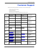
P-334WT User’s Guide Customer Support Please have the following information ready when you contact customer support. • • • • Product model and serial number. Warranty Information. Date that you received your device. Brief description of the problem and the steps you took to solve it. METHOD SUPPORT E-MAIL TELEPHONEA WEB SITE LOCATION SALES E-MAIL FAX FTP SITE support@zyxel.com.tw +886-3-578-3942 WORLDWIDE NORTH AMERICA GERMANY DENMARK NORWAY SWEDEN FINLAND www.zyxel.
P-334WT User’s Guide a. “+” is the (prefix) number you enter to make an international telephone call.
P-334WT User’s Guide Table of Contents Copyright .................................................................................................................. 2 Federal Communications Commission (FCC) Interference Statement ............... 3 ZyXEL Limited Warranty.......................................................................................... 5 Customer Support.................................................................................................... 6 Preface .....................
P-334WT User’s Guide 1.2.2.17 IP Multicast ....................................................................................40 1.2.2.18 IP Alias ..........................................................................................40 1.2.2.19 SNMP ............................................................................................40 1.2.2.20 Network Address Translation (NAT) ..............................................40 1.2.2.21 Traffic Redirect ............................................
P-334WT User’s Guide 3.6.3 DNS Server Address Assignment .............................................................62 3.6.4 WAN MAC Address ..................................................................................62 3.7 Basic Setup Complete ........................................................................................64 Chapter 4 Media Bandwidth Management Setup.................................................................. 66 4.1 Media Bandwidth Management Setup Overview .........
P-334WT User’s Guide 7.1.2 BSS ...........................................................................................................88 7.1.3 ESS ...........................................................................................................89 7.2 Wireless LAN Basics ..........................................................................................90 7.2.1 RTS/CTS .................................................................................................90 7.2.
P-334WT User’s Guide 8.18.1 Manual ..................................................................................................128 8.18.2 Automatic ..............................................................................................129 Chapter 9 WAN Screens........................................................................................................ 130 9.1 WAN Overview .................................................................................................130 9.
P-334WT User’s Guide 11.2.1 Configuring Route Entry ........................................................................161 Chapter 12 UPnP...................................................................................................................... 164 12.1 Universal Plug and Play Overview ................................................................164 12.1.1 How Do I Know If I'm Using UPnP? ......................................................164 12.1.2 NAT Traversal ....................
P-334WT User’s Guide Chapter 15 Content Filtering ................................................................................................. 192 15.1 Introduction to Content Filtering .....................................................................192 15.2 Restrict Web Features ...................................................................................192 15.3 Days and Times .............................................................................................192 15.
P-334WT User’s Guide Chapter 18 VPN Screens....................................................................................................... 214 18.1 VPN/IPSec Overview .....................................................................................214 18.2 IPSec Algorithms ............................................................................................214 18.2.1 AH (Authentication Header) Protocol ....................................................214 18.2.
P-334WT User’s Guide 20.1.3 Application and Subnet-based Bandwidth Management Example .......249 20.1.4 Bandwidth Usage Example ...................................................................250 20.1.5 Bandwidth Management Priorities ........................................................252 20.1.6 Bandwidth Management Services ........................................................252 20.1.6.1 Xbox Live ....................................................................................252 20.1.6.
P-334WT User’s Guide Chapter 23 Menu 1 General Setup ......................................................................................... 282 23.1 General Setup ................................................................................................282 23.2 Procedure To Configure Menu 1 ....................................................................282 23.2.1 Procedure to Configure Dynamic DNS .................................................284 Chapter 24 Menu 2 WAN Setup ..............
P-334WT User’s Guide Chapter 28 Static Route Setup ............................................................................................... 312 28.1 IP Static Route Setup .....................................................................................312 Chapter 29 Network Address Translation (NAT) ................................................................... 314 29.1 Using NAT ......................................................................................................314 29.1.
P-334WT User’s Guide Chapter 32 SNMP Configuration ............................................................................................ 346 32.1 About SNMP ..................................................................................................346 32.2 Supported MIBs ............................................................................................347 32.3 SNMP Configuration ......................................................................................347 32.
P-334WT User’s Guide 35.3 Restore Configuration ....................................................................................373 35.3.1 Restore Using FTP ...............................................................................373 35.3.2 Restore Using FTP Session Example ..................................................375 35.4 Uploading Firmware and Configuration Files .................................................375 35.4.1 Firmware File Upload ............................................
P-334WT User’s Guide 40.2 Using SA Monitor ...........................................................................................406 Appendix A PPPoE ................................................................................................................... 410 Appendix B PPTP...................................................................................................................... 412 Appendix C NetBIOS Filter Commands ...............................................................
P-334WT User’s Guide List of Figures Figure 1 Secure Internet Access via Cable, DSL or Wireless Modem ................................ 42 Figure 2 VPN Application .................................................................................................... 43 Figure 3 Internet Access Application Example .................................................................... 44 Figure 4 Change Password Screen ....................................................................................
P-334WT User’s Guide Figure 37 Wireless: Static WEP Encryption ........................................................................ 103 Figure 38 WPA - PSK Authentication .................................................................................. 106 Figure 39 Wireless: WPA-PSK ............................................................................................ 107 Figure 40 EAP Authentication .............................................................................................
P-334WT User’s Guide Figure 80 Remote Management: WWW ............................................................................. 198 Figure 81 Telnet Configuration on a TCP/IP Network ......................................................... 199 Figure 82 Remote Management: Telnet .............................................................................. 199 Figure 83 Remote Management: FTP .................................................................................
P-334WT User’s Guide Figure 123 Maintenance Configuration ............................................................................... 271 Figure 124 Configuration Restore Successful ..................................................................... 272 Figure 125 Temporarily Disconnected ................................................................................. 273 Figure 126 Configuration Restore Error ..............................................................................
P-334WT User’s Guide Figure 166 Multiple Servers Behind NAT Example ............................................................. 322 Figure 167 NAT Example 1 ................................................................................................. 322 Figure 168 Menu 4 Internet Access & NAT Example ......................................................... 323 Figure 169 NAT Example 2 .................................................................................................
P-334WT User’s Guide Figure 209 Menu 24.4 System Maintenance : Diagnostic ................................................... 366 Figure 210 LAN & WAN DHCP ........................................................................................... 366 Figure 211 Telnet in Menu 24.5 ........................................................................................... 370 Figure 212 FTP Session Example ......................................................................................
P-334WT User’s Guide Figure 252 Macintosh OS X: Apple Menu ........................................................................... 429 Figure 253 Macintosh OS X: Network ................................................................................. 430 Figure 254 Peer-to-Peer Communication in an Ad-hoc Network ........................................ 433 Figure 255 ESS Provides Campus-Wide Coverage ...........................................................
P-334WT User’s Guide 29 List of Figures
P-334WT User’s Guide List of Tables Table 1 IEEE 802.11b ......................................................................................................... 38 Table 2 IEEE 802.11g ......................................................................................................... 39 Table 3 Screens Summary ................................................................................................. 49 Table 4 Wizard 2: Wireless LAN Setup ....................................................
P-334WT User’s Guide Table 37 PPPoE Encapsulation ......................................................................................... 134 Table 38 PPTP Encapsulation ............................................................................................ 136 Table 39 WAN: IP ............................................................................................................... 138 Table 40 Traffic Redirect ....................................................................................
P-334WT User’s Guide Table 80 Media Mandwidth Management Priorities ........................................................... 252 Table 81 Commonly Used Services ................................................................................... 254 Table 82 Bandwidth Management Configuration ............................................................... 257 Table 83 Bandwidth Management Edit ............................................................................... 258 Table 84 Maintenance Status .
P-334WT User’s Guide Table 123 Menu 23.2 System Security : RADIUS Server .................................................. 351 Table 124 Menu 23.4 System Security : IEEE802.1x ......................................................... 353 Table 125 System Maintenance: Status Menu Fields ........................................................ 357 Table 126 Menu 24.2.1 System Maintenance : Information ............................................... 358 Table 127 Menu 24.3.
P-334WT User’s Guide Preface Congratulations on your purchase of the P-334WT, 802.11g Wireless Broadband Router with Firewall. This manual is designed to guide you through the configuration of your Prestige for its various applications. Note: Use the web configurator, System Management Terminal (SMT) or command interpreter interface to configure your Prestige. Not all features can be configured through all interfaces. This manual may refer to the P-334WT or 802.
P-334WT User’s Guide User Guide Feedback Help us help you! E-mail all User Guide-related comments, questions or suggestions for improvement to techwriters@zyxel.com.tw or send regular mail to The Technical Writing Team, ZyXEL Communications Corp., 6 Innovation Road II, Science-Based Industrial Park, Hsinchu, 300, Taiwan. Thank you! Syntax Conventions • “Enter” means for you to type one or more characters. “Select” or “Choose” means for you to use one predefined choices.
P-334WT User’s Guide CHAPTER 1 Getting to Know Your Prestige This chapter introduces the main features and applications of the Prestige. 1.1 Prestige Internet Security Gateway Overview The Prestige is the ideal secure gateway for all data passing between the Internet and LAN’s. By integrating NAT, firewall, media bandwidth management and VPN capability, ZyXEL’s Prestige is a complete security solution that protects your Intranet and efficiently manages data traffic on your network.
P-334WT User’s Guide 1.2.1.5 Reset Button The Prestige reset button is built into the rear panel. Use this button to restore the factory default password to 1234; IP address to 192.168.1.1, subnet mask to 255.255.255.0 and DHCP server enabled with a pool of 32 IP addresses starting at 192.168.1.33. 1.2.2 Non-Physical Features 1.2.2.1 OTIST One-Touch Intelligent Security Technology (OTIST) allows your Prestige to give wireless clients the Prestige’s security settings.
P-334WT User’s Guide 1.2.2.6 IEEE 802.1x Network Security The Prestige supports the IEEE 802.1x standard to enhance user authentication. Use the builtin user profile database to authenticate up to 32 users using MD5 encryption. Use an EAPcompatible RADIUS (RFC2138, 2139 - Remote Authentication Dial In User Service) server to authenticate a limitless number of users using EAP (Extensible Authentication Protocol). EAP is an authentication protocol that supports multiple types of authentication. 1.2.2.
P-334WT User’s Guide 1.2.2.10 802.11g Wireless LAN Standard The Prestige, complies with the 802.11g wireless standard and is also fully compatible with the 802.11b standard. This means an 802.11b radio card can interface directly with an 802.11g device (and vice versa) at 11 Mbps or lower depending on range. 802.11g has several intermediate rate steps between the maximum and minimum data rates. The 802.11g data rate and modulation are as follows: Table 2 IEEE 802.
P-334WT User’s Guide 1.2.2.17 IP Multicast Deliver IP packets to a specific group of hosts using IP multicast. IGMP (Internet Group Management Protocol) is the protocol used to support multicast groups. The latest version is version 2 (see RFC 2236); the Prestige supports both versions 1 and 2. 1.2.2.18 IP Alias IP Alias allows you to partition a physical network into logical networks over the same Ethernet interface.
P-334WT User’s Guide 1.2.2.24 Any IP The Any IP feature allows a computer to access the Internet without changing the network settings (such as IP address and subnet mask) of the computer, when the IP addresses of the computer and the Prestige are not in the same subnet. 1.2.2.25 Full Network Management The embedded web configurator is an all-platform web-based utility that allows you to easily access the Prestige’s management settings and configure the firewall.
P-334WT User’s Guide 1.3 Applications for the Prestige Here are some examples of what you can do with your Prestige. 1.3.1 Secure Broadband Internet Access via Cable or DSL Modem You can connect a cable modem, DSL or wireless modem to the Prestige for broadband Internet access via an Ethernet or a wireless port on the modem. The Prestige guarantees not only high speed Internet access, but secure internal network protection and traffic management as well.
P-334WT User’s Guide Figure 2 VPN Application 1.3.3 Internet Access Application Add a wireless LAN to your existing network without expensive network cables. Wireless stations can move freely anywhere in the coverage area and use resources on the wired network.
P-334WT User’s Guide Figure 3 Internet Access Application Example Chapter 1 Getting to Know Your Prestige 44
P-334WT User’s Guide 45 Chapter 1 Getting to Know Your Prestige
P-334WT User’s Guide CHAPTER 2 Introducing the Web Configurator This chapter describes how to access the Prestige web configurator and provides an overview of its screens. 2.1 Web Configurator Overview The embedded web configurator allows you to manage the Prestige from anywhere through a browser such as Microsoft Internet Explorer or Netscape Navigator. Use Internet Explorer 6.0 and later or Netscape Navigator 7.0 and later versions with JavaScript enabled.
P-334WT User’s Guide Figure 4 Change Password Screen You should now see the MAIN MENU screen) Note: The management session automatically times out when the time period set in the Administrator Inactivity Timer field expires (default five minutes). Simply log back into the Prestige if this happens to you 2.
P-334WT User’s Guide • Click to view the web configurator in the language of your choice. • Click LOGOUT at any time to exit the web configurator. • Click MAINTENANCE to view information about your Prestige or upgrade configuration/firmware files. Maintenance includes Status (Statistics), DHCP Table, F/ W (firmware) Upload, Configuration (Backup, Restore, Defaults) and Restart. Figure 5 The MAIN MENU Screen of the Web Configurator 2.3.
P-334WT User’s Guide The following table describes the sub-menus. Table 3 Screens Summary LINK FUNCTION WIZARD SETUP Use these screens for initial configuration including general setup, Wireless LAN setup, ISP parameters for Internet Access and WAN IP/DNS Server/MAC address assignment. BW SETUP Use these screens for initial configuration of media bandwidth management. SYSTEM General This screen contains administrative and system-related information. DDNS Use this screen to set up dynamic DNS.
P-334WT User’s Guide Table 3 Screens Summary LINK TAB FUNCTION REMOTE MGMT TELNET Use this screen to configure through which interface(s) and from which IP address(es) users can use Telnet to manage the Prestige. FTP Use this screen to configure through which interface(s) and from which IP address(es) users can use FTP to access the Prestige. WWW Use this screen to configure through which interface(s) and from which IP address(es) users can use HTTP to manage the Prestige.
P-334WT User’s Guide Table 3 Screens Summary LINK TAB FUNCTION MAINTENANCE Status This screen contains administrative and system-related information. DHCP Table This screen displays DHCP (Dynamic Host Configuration Protocol) related information and is READ-ONLY. Any IP Use this screen to allow a computer to access the Internet without changing the network settings of the computer, when the IP addresses of the computer and the Prestige are not in the same subnet.
P-334WT User’s Guide CHAPTER 3 Wizard Setup This chapter provides information on the Wizard Setup screens in the web configurator. 3.1 Wizard Setup Overview The web configurator’s setup wizard helps you configure your device to access the Internet. The second screen has three variations depending on what encapsulation type you use. Refer to your ISP checklist in the Quick Start Guide to know what to enter in each field. Leave a field blank if you don’t have that information. 3.
P-334WT User’s Guide Figure 6 Wizard 1: General Setup 3.3 Wizard Setup: Screen 2 Set up your wireless LAN using the second wizard screen. Figure 7 Wizard 2: Wireless LAN Setup The following table describes the labels in this screen. Table 4 Wizard 2: Wireless LAN Setup 53 LABEL DESCRIPTION Name(SSID) Enter a descriptive name (up to 32 printable 7-bit ASCII characters) for the wireless LAN.
P-334WT User’s Guide Table 4 Wizard 2: Wireless LAN Setup LABEL DESCRIPTION Security The level of Security can be selected as none, basic or extended. Choose None to have no wireless LAN security configured and proceed to the ISP Parameters for Internet Access screen. Choose Basic(WEP) security if you want to configure WEP Encryption parameters. Choose Extend(WPA-PSK) security to configure a Pre-Shared Key. The third screen varies depending on which security level you select.
P-334WT User’s Guide Figure 8 Wizard 3: Wireless LAN Setup: Basic Security The following table describes the labels in this screen. Table 5 Wizard 3: Wireless LAN Setup: Basic Security LABEL DESCRIPTION Passphrase Enter a Passphrase (up to 32 printable characters) and clicking Generate. The Prestige automatically generates a WEP key. WEP Encryption Select 64-bit WEP, 128-bit WEP or 256-bit WEP to allow data encryption. ASCII Select this option in order to enter ASCII characters as the WEP keys.
P-334WT User’s Guide Choose Extend(WPA-PSK) security in the Wireless LAN Setup screen to set up a PreShared Key. Figure 9 Wizard 3: Wireless LAN Setup: Extend Security The following table describes the labels in this screen. Table 6 Wizard 3: Wireless LAN Setup: Extend Security LABEL DESCRIPTION Pre-Shared Key Type from 8 to 31 case-sensitive ASCII characters. You can set up the most secure wireless connection by configuring WPA in the advanced wireless screen.
P-334WT User’s Guide Figure 10 Wizard 4: Ethernet Encapsulation The following table describes the labels in this screen. Table 7 Wizard 4: Ethernet Encapsulation LABEL DESCRIPTION ISP Parameters for Internet Access Encapsulation You must choose the Ethernet option when the WAN port is used as a regular Ethernet. Otherwise, choose PPP over Ethernet or PPTP for a dial-up connection.
P-334WT User’s Guide For the service provider, PPPoE offers an access and authentication method that works with existing access control systems (for instance, Radius). For the user, PPPoE provides a login and authentication method that the existing Microsoft Dial-Up Networking software can activate, and therefore requires no new learning or procedures for Windows users.
P-334WT User’s Guide Table 8 Wizard 4: PPPoE Encapsulation LABEL DESCRIPTION Idle Timeout Type the time in seconds that elapses before the router automatically disconnects from the PPPoE server. The default time is 100 seconds. Next Click Next to continue. Back Click Back to return to the previous screen. 3.5.
P-334WT User’s Guide Figure 12 Wizard 4: PPTP Encapsulation The following table describes the fields in this screen Table 9 Wizard 4: PPTP Encapsulation LABEL DESCRIPTION ISP Parameters for Internet Access Encapsulation Select PPTP from the drop-down list box. User Name Type the user name given to you by your ISP. Password Type the password associated with the User Name above. Nailed-Up Connection Select Nailed-Up Connection if you do not want the connection to time out.
P-334WT User’s Guide 3.6 Wizard Setup: Screen 5 The fifth wizard screen allows you to configure WAN IP address assignment, DNS server address assignment and the WAN MAC address. 3.6.1 WAN IP Address Assignment Every computer on the Internet must have a unique IP address. If your networks are isolated from the Internet, for instance, only between your two branch offices, you can assign any IP addresses to the hosts without problems.
P-334WT User’s Guide Let's say you select 192.168.1.0 as the network number; which covers 254 individual addresses, from 192.168.1.1 to 192.168.1.254 (zero and 255 are reserved). In other words, the first three numbers specify the network number while the last number identifies an individual computer on that network. Once you have decided on the network number, pick an IP address that is easy to remember, for instance, 192.168.1.
P-334WT User’s Guide The fifth wizard screen varies according to the type of encapsulation that you select in the third wizard screen. Figure 13 Wizard 5: WAN Setup The following table describes the labels in this screen Table 12 Wizard 5: WAN Setup LABEL DESCRIPTION WAN IP Address Assignment Get automatically from ISP Select this option If your ISP did not assign you a fixed IP address. This is the default selection. Use fixed IP address Select this option If the ISP assigned a fixed IP address.
P-334WT User’s Guide Table 12 Wizard 5: WAN Setup LABEL DESCRIPTION First DNS Server Select From ISP if your ISP dynamically assigns DNS server information (and the Prestige's WAN IP address). The field to the right displays the (read-only) DNS server IP address that the ISP assigns. Select User-Defined if you have the IP address of a DNS server. Enter the DNS server's IP address in the field to the right. Select None if you do not want to configure DNS servers.
P-334WT User’s Guide Figure 14 Wizard Finish Well done! You have successfully set up your Prestige to operate on your network and access the Internet 65 Chapter 3 Wizard Setup
P-334WT User’s Guide CHAPTER 4 Media Bandwidth Management Setup This chapter provides information on the bandwidth management setup screens in the web configurator. 4.1 Media Bandwidth Management Setup Overview The web configurator’s BW SETUP allows you to specify bandwidth classes based on an application and/or subnet. You can allocate specific amounts of bandwidth capacity (bandwidth budgets) to different bandwidth classes.
P-334WT User’s Guide Figure 15 Media Bandwidth Management Setup 1 The following fields describe the label in this screen. Table 13 Media Bandwidth Management Setup LABEL DESCRIPTION Active Select the Active check box to have the Prestige apply bandwidth management to traffic going out through the Prestige’s WAN, LAN or WLAN port. Managed Bandwidth (Kbps) Enter the amount of Managed Bandwidth in kbps (2 to 100,000) that you want to allocate for traffic. 20 kbps to 20,000 kbps is recommended.
P-334WT User’s Guide Figure 16 Media Bandwidth Management Setup 2: Services The following table describes the labels in this screen. Table 14 Media Bandwidth Management Setup 2: Services LABEL DESCRIPTION Choose Channel ID Create bandwidth management classes by selecting services from the list provided. • XBox Live • VoIP (SIP) • FTP • E-Mail • eMule/eDonkey • WWW For a detailed description of these services, see the Media Bandwidth Management chapter. Back Click Back to display the previous screen.
P-334WT User’s Guide Figure 17 Media Bandwidth Management Setup 3: Service Priority The following table describes the fields in this screen. Table 15 Media Bandwidth Management Setup 3: Service Priority LABELS DESCRIPTION Service These fields display the services selected in the previous screen. Priority Select High, Mid or Low priority for each service to have your Prestige use a priority for traffic that matches that service.
P-334WT User’s Guide CHAPTER 5 System Screens This chapter provides information on the System screens. 5.1 System Overview See the Wizard Setup chapter for more information on the next few screens. 5.2 Configuring General Setup Click SYSTEM to open the General screen.
P-334WT User’s Guide Figure 19 System General Setup The following table describes the labels in this screen. Table 16 System General Setup LABEL DESCRIPTION System Name Choose a descriptive name for identification purposes. It is recommended you enter your computer’s “Computer name” in this field (see the Wizard Setup chapter for how to find your computer’s name). This name can be up to 30 alphanumeric characters long. Spaces are not allowed, but dashes “-” and underscores "_" are accepted.
P-334WT User’s Guide Table 16 System General Setup LABEL DESCRIPTION First DNS Server Select From ISP if your ISP dynamically assigns DNS server information (and the Prestige's WAN IP address). The field below displays the (read-only) DNS server Second DNS Server IP address that the ISP assigns. Third DNS Server Select User-Defined if you have the IP address of a DNS server. Enter the DNS server's IP address in the field below. If you chose User-Defined, but leave the IP address set to 0.0.0.
P-334WT User’s Guide Figure 20 DDNS The following table describes the labels in this screen. Table 17 DDNS LABEL DESCRIPTION Enable DDNS Select this check box to use dynamic DNS. Service Provider Select the name of your Dynamic DNS service provider. DDNS Type Select the type of service that you are registered for from your Dynamic DNS service provider. Host Names 1~3 Enter the host names in the three fields provided. You can specify up to two host names in each field separated by a comma (",").
P-334WT User’s Guide Table 17 DDNS LABEL DESCRIPTION Use specified IP Address Type the IP address of the host name(s). Use this if you have a static IP address. Apply Click Apply to save your changes back to the Prestige. Reset Click Reset to begin configuring this screen afresh. 5.5 Configuring Password To change your Prestige’s password (recommended), click SYSTEM, then the Password tab. The screen appears as shown. This screen allows you to change the Prestige’s password.
P-334WT User’s Guide Figure 22 Time Setting The following table describes the labels in this screen. Table 19 Time Setting 75 LABEL DESCRIPTION Time Protocol Select the time service protocol that your time server sends when you turn on the Prestige. Not all time servers support all protocols, so you may have to check with your ISP/network administrator or use trial and error to find a protocol that works. The main difference between them is the format.
P-334WT User’s Guide Table 19 Time Setting LABEL DESCRIPTION Current Date This field displays the date of your Prestige. Each time you reload this page, the Prestige synchronizes the time with the time server. New Date This field displays the last updated date from the time server. When you select None in the Time Protocol field, enter the new date in this field and then click Apply. Time Zone Choose the Time Zone of your location.
P-334WT User’s Guide 77 Chapter 5 System Screens
P-334WT User’s Guide CHAPTER 6 LAN Screens This chapter describes how to configure LAN settings. 6.1 LAN Overview Local Area Network (LAN) is a shared communication system to which many computers are attached. The LAN screens can help you configure a LAN DHCP server, manage IP addresses, and partition your physical network into logical networks. 6.
P-334WT User’s Guide • IP address of 192.168.1.1 with subnet mask of 255.255.255.0 (24 bits) • DHCP server enabled with 32 client IP addresses starting from 192.168.1.33. These parameters should work for the majority of installations. If your ISP gives you explicit DNS server address(es), read the embedded web configurator help regarding what fields need to be configured. 6.3.2 IP Address and Subnet Mask Refer to the IP Address and Subnet Mask section in the Wizard Setup chapter for this information. 6.
P-334WT User’s Guide 224.0.0.0 is not assigned to any group and is used by IP multicast computers. The address 224.0.0.1 is used for query messages and is assigned to the permanent group of all IP hosts (including gateways). All hosts must join the 224.0.0.1 group in order to participate in IGMP. The address 224.0.0.2 is assigned to the multicast routers group. The Prestige supports both IGMP version 1 (IGMP-v1) and IGMP version 2 (IGMP-v2).
P-334WT User’s Guide The Any IP feature does not apply to a computer using either a dynamic IP address or a static IP address that is in the same subnet as the Prestige’s IP address. Note: You must enable NAT/SUA to use the Any IP feature on the Prestige 6.4.1 How Any IP Works Address Resolution Protocol (ARP) is a protocol for mapping an Internet Protocol address (IP address) to a physical machine address, also known as a Media Access Control or MAC address, on the local area network.
P-334WT User’s Guide Figure 24 LAN IP The following table describes the labels in this screen. Table 20 LAN IP LABEL DESCRIPTION DHCP Server DHCP (Dynamic Host Configuration Protocol, RFC 2131 and RFC 2132) allows individual clients (computers) to obtain TCP/IP configuration at startup from a server. Leave the DHCP Server check box selected unless your ISP instructs you to do otherwise. Clear it to disable the Prestige acting as a DHCP server.
P-334WT User’s Guide Table 20 LAN IP LABEL DESCRIPTION DNS Servers Assigned by DHCP Server The Prestige passes a DNS (Domain Name System) server IP address (in the order you specify here) to the DHCP clients. The Prestige only passes this information to the LAN DHCP clients when you select the DHCP Server check box.
P-334WT User’s Guide Table 20 LAN IP LABEL DESCRIPTION Any IP Setup Active Select this option to activate the Any-IP feature. This allows a computer to access the Internet without changing the network settings (such as IP address and subnet mask) of the computer, even when the IP addresses of the computer and the Prestige are not in the same subnet.
P-334WT User’s Guide Figure 25 Static DHCP The following table describes the labels in this screen. Table 21 Static DHCP LABEL DESCRIPTION # This is the index number of the Static IP table entry (row). MAC Address Type the MAC address (with colons) of a computer on your LAN. IP Address This field specifies the size, or count of the IP address pool. Apply Click Apply to save your changes back to the Prestige. Reset Click Reset to begin configuring this screen afresh. 6.
P-334WT User’s Guide Figure 26 IP Alias The following table describes the labels in this screen. Table 22 IP Alias LABEL DESCRIPTION IP Alias 1,2 Select the check box to configure another LAN network for the Prestige. IP Address Enter the IP address of your Prestige in dotted decimal notation. IP Subnet Mask Your Prestige will automatically calculate the subnet mask based on the IP address that you assign. Unless you are implementing subnetting, use the subnet mask computed by the Prestige.
P-334WT User’s Guide 87 Chapter 6 LAN Screens
P-334WT User’s Guide CHAPTER 7 Wireless Configuration and Roaming This chapter discusses how to configure the Wireless and Roaming screens on the Prestige. 7.1 Wireless LAN Overview This section introduces the wireless LAN(WLAN) and some basic scenarios. 7.1.1 IBSS An Independent Basic Service Set (IBSS), also called an Ad-hoc network, is the simplest WLAN configuration.
P-334WT User’s Guide Figure 28 Basic Service set 7.1.3 ESS An Extended Service Set (ESS) consists of a series of overlapping BSSs, each containing an access point, with each access point connected together by a wired network. This wired connection between APs is called a Distribution System (DS). An ESSID (ESS IDentification) uniquely identifies each ESS. All access points and their associated wireless stations within the same ESS must have the same ESSID in order to communicate.
P-334WT User’s Guide Figure 29 Extended Service Set 7.2 Wireless LAN Basics Refer also to the Wizard Setup chapter for more background information on Wireless LAN features, such as channels. 7.2.1 RTS/CTS A hidden node occurs when two stations are within range of the same access point, but are not within range of each other. The following figure illustrates a hidden node.
P-334WT User’s Guide Figure 30 RTS/CTS When station A sends data to the Prestige, it might not know that station B is already using the channel. If these two stations send data at the same time, collisions may occur when both sets of data arrive at the AP at the same time, resulting in a loss of messages for both stations. RTS/CTS is designed to prevent collisions due to hidden nodes.
P-334WT User’s Guide A large Fragmentation Threshold is recommended for networks not prone to interference while you should set a smaller threshold for busy networks or networks that are prone to interference. If the Fragmentation Threshold value is smaller than the RTS/CTS value (see previously) you set, then the RTS (Request To Send)/CTS (Clear to Send) handshake will never occur as data frames will be fragmented before they reach RTS/CTS size. 7.
P-334WT User’s Guide Figure 31 Wireless The following table describes the general wireless LAN labels in this screen. Table 23 Wireless LABEL DESCRIPTION Enable Wireless LAN Click the check box to activate wireless LAN. Name(SSID) (Service Set IDentity) The SSID identifies the Service Set with which a wireless station is associated. Wireless stations associating to the access point (AP) must have the same SSID. Enter a descriptive name (up to 32 printable 7-bit ASCII characters) for the wireless LAN.
P-334WT User’s Guide Table 23 Wireless LABEL DESCRIPTION Hide Name(SSID) Select this check box to hide the SSID in the outgoing beacon frame so a station cannot obtain the SSID through passive scanning using a site survey tool. Choose Channel ID Set the operating frequency/channel depending on your particular region. Select a channel from the drop-down list box. Refer to the Wizard Setup chapter for more information on channels. RTS/CTS Threshold Enter a value between 0 and 2432. The default is 4096.
P-334WT User’s Guide Figure 32 Roaming Example The steps below describe the roaming process. 1 As wireless station Y moves from the coverage area of access point P1 to that of access point 2 P2, it scans and uses the signal of access point P2. 3 Access point P2 acknowledges the presence of wireless station Y and relays this information to access point P1 through the wired LAN. 4 Access point P1 updates the new position of wireless station.
P-334WT User’s Guide To enable roaming on your Prestige, click the WIRELESS link under ADVANCED and then the Roaming tab. The screen appears as shown. Figure 33 Roaming The following table describes the labels in this screen. Table 24 Roaming LABEL DESCRIPTION Active Select Yes from the drop-down list box to enable roaming on the Prestige if you have two or more Prestiges on the same subnet. Note: All APs on the same subnet and the wireless stations must have the same SSID to allow roaming.
P-334WT User’s Guide 97 Chapter 7 Wireless Configuration and Roaming
P-334WT User’s Guide CHAPTER 8 Wireless Security This Chapter describes how to use the MAC Filter, Roaming and OTIST to configure wireless security on your Prestige. 8.1 Wireless Security Overview Wireless security is vital to your network to protect wireless communication between wireless stations, access points and the wired network. The figure below shows the possible wireless security levels on your Prestige.
P-334WT User’s Guide Figure 35 Wireless: No Security The following table describes the labels in this screen. Table 25 Wireless No Security 99 LABEL DESCRIPTION Security Choose No Security from the drop-down list box. Preamble Select a preamble type from the drop-down list menu. Choices are Long, Short and Dynamic. The default setting is Long. See the section on preamble for more information.
P-334WT User’s Guide Table 25 Wireless No Security LABEL DESCRIPTION 802.11 Mode Select 802.11b Only to allow only IEEE 802.11b compliant WLAN devices to associate with the Prestige. Select 802.11g Only to allow only IEEE 802.11g compliant WLAN devices to associate with the Prestige. Select Mixed to allow either IEEE802.11b or IEEE802.11g compliant WLAN devices to associate with the Prestige. The transmission rate of your Prestige might be reduced.
P-334WT User’s Guide 8.3 WEP Overview WEP (Wired Equivalent Privacy) as specified in the IEEE 802.11 standard provides methods for both data encryption and wireless station authentication. 8.3.1 Data Encryption WEP provides a mechanism for encrypting data using encryption keys. Both the AP and the wireless stations must use the same WEP key to encrypt and decrypt data. Your Prestige allows you to configure up to four 64-bit, 128-bit or 256-bit WEP keys, but only one key can be enabled at any one time. 8.
P-334WT User’s Guide Shared key authentication involves a four-message procedure. A wireless station sends a shared key authentication request to the AP, which will then reply with a challenge text message. The wireless station must then use the AP’s default WEP key to encrypt the challenge text and return it to the AP, which attempts to decrypt the message using the AP’s default WEP key. If the decrypted message matches the challenge text, the wireless station is authenticated.
P-334WT User’s Guide Figure 37 Wireless: Static WEP Encryption The following table describes the wireless LAN security labels in this screen. Table 27 Wireless: Static WEP Encryption 103 LABEL DESCRIPTION Passphrase Enter a Passphrase (up to 32 printable characters) and clicking Generate. The Prestige automatically generates a WEP key. WEP Encryption Select 64-bit WEP, 128-bit WEP or 256-bit WEP to enable data encryption.
P-334WT User’s Guide Table 27 Wireless: Static WEP Encryption LABEL DESCRIPTION Authentication Method This field is activated when you select 64-bit WEP, 128-bit WEP or 256-bit WEP in the WEP Encryption field. Select Auto, Open System or Shared Key from the drop-down list box. ASCII Select this option in order to enter ASCII characters as WEP key. Hex Select this option in order to enter hexadecimal characters as a WEP key.
P-334WT User’s Guide Therefore, if you don’t have an external RADIUS server you should use WPA-PSK (WPA Pre-Shared Key) that only requires a single (identical) password entered into each access point, wireless gateway and wireless client. As long as the passwords match, a client will be granted access to a WLAN. 8.5.2 Encryption WPA improves data encryption by using Temporal Key Integrity Protocol (TKIP), Message Integrity Check (MIC) and IEEE 802.1x.
P-334WT User’s Guide 4 The AP and wireless clients use the TKIP encryption process to encrypt data exchanged between them. Figure 38 WPA - PSK Authentication 8.6 Configuring WPA-PSK Authentication In order to configure and enable WPA-PSK Authentication; click the WIRELESS link under ADVANCED to display the Wireless screen. Select WPA-PSK from the Security list.
P-334WT User’s Guide Figure 39 Wireless: WPA-PSK The following table describes the labels in this screen. Table 28 Wireless: WPA-PSK LABEL DESCRIPTION Pre-Shared Key The encryption mechanisms used for WPA and WPA-PSK are the same. The only difference between the two is that WPA-PSK uses a simple common password, instead of user-specific credentials. Type a pre-shared key from 8 to 63 case-sensitive ASCII characters (including spaces and symbols).
P-334WT User’s Guide Table 28 Wireless: WPA-PSK LABEL DESCRIPTION Idle Timeout The Prestige automatically disconnects a wireless station from the wired network after a period of inactivity. The wireless station needs to enter the username and password again before access to the wired network is allowed. The default time interval is 3600 seconds (or 1 hour).
P-334WT User’s Guide • Accounting Keeps track of the client’s network activity. RADIUS user is a simple package exchange in which your Prestige acts as a message relay between the wireless station and the network RADIUS server. 8.8.1 Types of RADIUS Messages The following types of RADIUS messages are exchanged between the access point and the RADIUS server for user authentication: • Access-Request Sent by an access point requesting authentication. • Access-Reject Sent by a RADIUS server rejecting access.
P-334WT User’s Guide The type of authentication you use depends on the RADIUS server or the AP. The Prestige supports EAP-TLS, EAP-TTLS and PEAP with RADIUS. Refer to the Types of EAP Authentication appendix for descriptions on the four common types. Your Prestige supports EAP-MD5 (Message-Digest Algorithm 5) with RADIUS. The following figure shows an overview of authentication when you specify a RADIUS server on your access point.
P-334WT User’s Guide Figure 41 WPA with RADIUS Application Example 8.9 Configuring WPA Authentication In order to configure and enable WPA Authentication; click the WIRELESS link under ADVANCED to display the Wireless screen. Select WPA from the Security list.
P-334WT User’s Guide Figure 42 Wireless: WPA Chapter 8 Wireless Security 112
P-334WT User’s Guide The following table describes the labels in this screen. Table 29 Wireless: WPA LABEL DESCRIPTION ReAuthentication Timer (in seconds) Specify how often wireless stations have to reenter usernames and passwords in order to stay connected. Enter a time interval between 10 and 9999 seconds. The default time interval is 1800 seconds (30 minutes). Note: If wireless station authentication is done using a RADIUS server, the reauthentication timer on the RADIUS server has priority.
P-334WT User’s Guide Table 29 Wireless: WPA LABEL DESCRIPTION 802.11 Mode Select 802.11b Only to allow only IEEE 802.11b compliant WLAN devices to associate with the Prestige. Select 802.11g Only to allow only IEEE 802.11g compliant WLAN devices to associate with the Prestige. Select Mixed to allow either IEEE802.11b or IEEE802.11g compliant WLAN devices to associate with the Prestige. The transmission rate of your Prestige might be reduced.
P-334WT User’s Guide 8.12 Configuring 802.1x and Dynamic WEP Key Exchange In order to configure and enable 802.1x and Dynamic WEP Key Exchange; click the WIRELESS link under ADVANCED to display the Wireless screen. Select 802.1x + Dynamic WEP from the Security list.
P-334WT User’s Guide Figure 43 Wireless: 802.
P-334WT User’s Guide The following table describes the labels in this screen. Table 30 Wireless: 802.1x and Dynamic WEP LABEL DESCRIPTION ReAuthentication Timer (in seconds) Specify how often wireless stations have to reenter usernames and passwords in order to stay connected. Enter a time interval between 10 and 9999 seconds. The default time interval is 1800 seconds (30 minutes).
P-334WT User’s Guide Table 30 Wireless: 802.1x and Dynamic WEP LABEL DESCRIPTION 802.11 Mode Select 802.11b Only to allow only IEEE 802.11b compliant WLAN devices to associate with the Prestige. Select 802.11g Only to allow only IEEE 802.11g compliant WLAN devices to associate with the Prestige. Select Mixed to allow either IEEE802.11b or IEEE802.11g compliant WLAN devices to associate with the Prestige. The transmission rate of your Prestige might be reduced.
P-334WT User’s Guide Figure 44 Wireless: 802.
P-334WT User’s Guide The following table describes the labels in this screen. Table 31 Wireless: 802.1x and Static WEP LABEL DESCRIPTION Passphrase Enter a Passphrase (up to 32 printable characters) and clicking Generate. The Prestige automatically generates a WEP key. WEP Encryption Select 64-bit WEP, 128-bit WEP or 256-bit WEP to enable data encryption. Authentication Method This field is activated when you select 64-bit WEP, 128-bit WEP or 256-bit WEP in the WEP Encryption field.
P-334WT User’s Guide Table 31 Wireless: 802.1x and Static WEP LABEL DESCRIPTION IP Address Enter the IP address of the external accounting server in dotted decimal notation. Port Number Enter the port number of the external accounting server. The default port number is 1813. You need not change this value unless your network administrator instructs you to do so with additional information.
P-334WT User’s Guide Figure 45 Wireless: 802.
P-334WT User’s Guide The following table describes the labels in this screen. Table 32 Wireless: 802.1x and No WEP LABEL DESCRIPTION ReAuthentication Timer (in seconds) Specify how often wireless stations have to reenter usernames and passwords in order to stay connected. Enter a time interval between 10 and 9999 seconds. The default time interval is 1800 seconds (30 minutes).
P-334WT User’s Guide Table 32 Wireless: 802.1x and No WEP LABEL DESCRIPTION G+ Enhanced Select G+ Enhanced checkbox to allow any ZyXEL WLAN devices that support this feature to associate with the Prestige. This permits the Prestige to transmit at a higher speed than the 802.11g Only mode. Apply Click Apply to save your changes back to the Prestige. Reset Click Reset to reload the previous configuration for this screen. 8.
P-334WT User’s Guide Figure 46 MAC Address Filter The following table describes the labels in this menu. Table 33 MAC Address Filter 125 LABEL DESCRIPTION Active Select Yes from the drop down list box to enable MAC address filtering. Filter Action Define the filter action for the list of MAC addresses in the MAC Address table.
P-334WT User’s Guide Table 33 MAC Address Filter LABEL DESCRIPTION MAC Address Enter the MAC addresses of the wireless station that are allowed or denied access to the Prestige in these address fields. Enter the MAC addresses in a valid MAC address format, that is, six hexadecimal character pairs, for example, 12:34:56:78:9a:bc. Apply Click Apply to save your changes back to the Prestige. Reset Click Reset to reload the previous configuration for this screen. 8.
P-334WT User’s Guide 8.17.2 Web Configurator Use the web configurator to set up an OTIST Setup Key by using either the default OTIST Setup Key or by typing a new one. If you change the OTIST Setup Key on the Prestige, you must also change the wireless client OTIST Setup Key field. 1 To activate OTIST on the Prestige using the web configurator, click the WIRELESS link under ADVANCED and then the OTIST tab. The screen appears as shown next.
P-334WT User’s Guide Figure 48 OTIST Start 3 The process takes three minutes. During this time the OTIST-enabled wireless clients search for a Prestige to associate. Figure 49 OTIST Process 4 When the previous screen closes, your current Prestige security configuration are automatically saved to the wireless clients. 8.18 Wireless Client OTIST Configuration The following methods show how to configure the wireless client for OTIST.
P-334WT User’s Guide • • Click No to return to the wireless client’s main page. Click Yes to display an access point or wireless router that is within range of the wireless client. Select the access point or router from which you want to have wireless settings assigned. 6 Click the Save button in the Adapter screen to save the settings to the wireless client. 8.18.
P-334WT User’s Guide CHAPTER 9 WAN Screens This chapter describes how to configure WAN settings. 9.1 WAN Overview See the Wizard Setup chapter for more information on the fields in the WAN screens. 9.2 TCP/IP Priority (Metric) The metric represents the "cost of transmission". A router determines the best route for transmission by choosing a path with the lowest "cost". RIP routing uses hop count as the measurement of cost, with a minimum of "1" for directly connected networks.
P-334WT User’s Guide Figure 50 WAN: Route The following table describes the labels in this screen. Table 35 WAN: Route LABEL DESCRIPTION WAN Traffic Redirect The metric represents the "cost of transmission". A router determines the best route for transmission by choosing a path with the lowest "cost". RIP routing uses hop count as the measurement of cost, with a minimum of "1" for directly connected networks. The number must be between "1" and "15"; a number greater than "15" means the link is down.
P-334WT User’s Guide Figure 51 Ethernet Encapsulation The following table describes the labels in this screen. Table 36 Ethernet Encapsulation LABEL DESCRIPTION Encapsulation You must choose the Ethernet option when the WAN port is used as a regular Ethernet. Service Type Choose from Standard, Telstra (RoadRunner Telstra authentication method), RR-Manager (Roadrunner Manager authentication method), RR-Toshiba (Roadrunner Toshiba authentication method) or Telia Login.
P-334WT User’s Guide For the service provider, PPPoE offers an access and authentication method that works with existing access control systems (for example Radius). PPPoE provides a login and authentication method that the existing Microsoft Dial-Up Networking software can activate, and therefore requires no new learning or procedures for Windows users. One of the benefits of PPPoE is the ability to let you access one of multiple network services, a function known as dynamic service selection.
P-334WT User’s Guide Figure 52 PPPoE Encapsulation The following table describes the labels in this screen. Table 37 PPPoE Encapsulation LABEL DESCRIPTION ISP Parameters for Internet Access Encapsulation The PPP over Ethernet choice is for a dial-up connection using PPPoE. The Prestige supports PPPoE (Point-to-Point Protocol over Ethernet). PPPoE is an IETF Draft standard (RFC 2516) specifying how a personal computer (PC) interacts with a broadband modem (i.e. xDSL, cable, wireless, etc.) connection.
P-334WT User’s Guide 9.4.3 PPTP Encapsulation Point-to-Point Tunneling Protocol (PPTP) is a network protocol that enables secure transfer of data from a remote client to a private server, creating a Virtual Private Network (VPN) using TCP/IP-based networks. PPTP supports on-demand, multi-protocol and virtual private networking over public networks, such as the Internet. The screen shown next is for PPTP encapsulation.
P-334WT User’s Guide Figure 53 PPTP Encapsulation The following table describes the labels in this screen. Table 38 PPTP Encapsulation LABEL DESCRIPTION ISP Parameters for Internet Access Encapsulation Point-to-Point Tunneling Protocol (PPTP) is a network protocol that enables secure transfer of data from a remote client to a private server, creating a Virtual Private Network (VPN) using TCP/IP-based networks.
P-334WT User’s Guide Table 38 PPTP Encapsulation LABEL DESCRIPTION My IP Subnet Mask Your Prestige will automatically calculate the subnet mask based on the IP address that you assign. Unless you are implementing subnetting, use the subnet mask computed by the Prestige. Server IP Address Type the IP address of the PPTP server. Connection ID/Name Type your identification name for the PPTP server. Apply Click Apply to save your changes back to the Prestige.
P-334WT User’s Guide Figure 54 WAN: IP The following table describes the labels in this screen. Table 39 WAN: IP LABEL DESCRIPTION WAN IP Address Assignment Get automatically from Select this option If your ISP did not assign you a fixed IP address. This is the ISP default selection. Use fixed IP address Select this option If the ISP assigned a fixed IP address. My WAN IP Address Enter your WAN IP address in this field if you selected Use Fixed IP Address.
P-334WT User’s Guide Table 39 WAN: IP 139 LABEL DESCRIPTION Network Address Translation Network Address Translation (NAT) allows the translation of an Internet protocol address used within one network (for example a private IP address used in a local network) to a different IP address known within another network (for example a public IP address used on the Internet). Choose None to disable NAT. Choose SUA Only if you have a single public IP address.
P-334WT User’s Guide Table 39 WAN: IP LABEL DESCRIPTION Multicast Choose None (default), IGMP-V1 or IGMP-V2. IGMP (Internet Group Multicast Protocol) is a network-layer protocol used to establish membership in a Multicast group - it is not used to carry user data. IGMP version 2 (RFC 2236) is an improvement over version 1 (RFC 1112) but IGMP version 1 is still in wide use.
P-334WT User’s Guide Otherwise, click Spoof this computer's MAC address - IP Address and enter the IP address of the computer on the LAN whose MAC you are cloning. Once it is successfully configured, the address will be copied to the rom file (ZyNOS configuration file). It will not change unless you change the setting or upload a different ROM file. It is recommended that you clone the MAC address prior to hooking up the WAN Port. 9.
P-334WT User’s Guide Figure 57 Traffic Redirect LAN Setup 9.8 Configuring Traffic Redirect To change your Prestige’s Traffic Redirect settings, click WAN, then the Traffic Redirect tab. The screen appears as shown.
P-334WT User’s Guide Figure 58 WAN: Traffic Redirect The following table describes the labels in this screen. Table 40 Traffic Redirect LABEL DESCRIPTION Active Select this check box to have the Prestige use traffic redirect if the normal WAN connection goes down. Backup Gateway IP Address Type the IP address of your backup gateway in dotted decimal notation. The Prestige automatically forwards traffic to this IP address if the Prestige's Internet connection terminates.
P-334WT User’s Guide Table 40 Traffic Redirect LABEL DESCRIPTION Apply Click Apply to save your changes back to the Prestige. Reset Click Reset to begin configuring this screen afresh.
P-334WT User’s Guide 145 Chapter 9 WAN Screens
P-334WT User’s Guide CHAPTER 10 Network Address Translation (NAT) Screens This chapter discusses how to configure NAT on the Prestige. 10.1 NAT Overview NAT (Network Address Translation - NAT, RFC 1631) is the translation of the IP address of a host in a packet. For example, the source address of an outgoing packet, used within one network is changed to a different IP address known within another network. 10.1.1 NAT Definitions Inside/outside denotes where a host is located relative to the Prestige.
P-334WT User’s Guide Note: NAT never changes the IP address (either local or global) of an outside host. 10.1.2 What NAT Does In the simplest form, NAT changes the source IP address in a packet received from a subscriber (the inside local address) to another (the inside global address) before forwarding the packet to the WAN side.
P-334WT User’s Guide Figure 59 How NAT Works 10.1.4 NAT Application The following figure illustrates a possible NAT application, where three inside LANs (logical LANs using IP Alias) behind the Prestige can communicate with three distinct WAN networks. More examples follow at the end of this chapter. Figure 60 NAT Application With IP Alias 10.1.5 NAT Mapping Types NAT supports five types of IP/port mapping.
P-334WT User’s Guide • One to One: In One-to-One mode, the Prestige maps one local IP address to one global IP address. • Many to One: In Many-to-One mode, the Prestige maps multiple local IP addresses to one global IP address. This is equivalent to SUA (i.e., PAT, port address translation), ZyXEL’s Single User Account feature (the SUA Only option). • Many-to-Many Overload: In Many-to-Many Overload mode, the Prestige maps the multiple local IP addresses to shared global IP addresses.
P-334WT User’s Guide 10.2 Using NAT Note: You must create a firewall rule in addition to setting up SUA/NAT, to allow traffic from the WAN to be forwarded through the Prestige. 10.2.1 SUA (Single User Account) Versus NAT SUA (Single User Account) is a ZyNOS implementation of a subset of NAT that supports two types of mapping, Many-to-One and Server.
P-334WT User’s Guide 10.3.2 Port Forwarding: Services and Port Numbers A NAT server set is a list of inside (behind NAT on the LAN) servers, for example, web or FTP, that you can make accessible to the outside world even though NAT makes your whole inside network appear as a single machine to the outside world. Use the SUA Server page to forward incoming service requests to the server(s) on your local network.
P-334WT User’s Guide 10.3.3 Configuring Servers Behind SUA (Example) Let's say you want to assign ports 21-25 to one FTP, Telnet and SMTP server (A in the example), port 80 to another (B in the example) and assign a default server IP address of 192.168.1.35 to a third (C in the example). You assign the LAN IP addresses and the ISP assigns the WAN IP address. The NAT network appears as a single host on the Internet Figure 61 Multiple Servers Behind NAT Example 10.
P-334WT User’s Guide Figure 62 SUA/NAT Setup The following table describes the labels in this screen. Table 44 SUA/NAT Setup LABEL DESCRIPTION Default Server In addition to the servers for specified services, NAT supports a default server. A default server receives packets from ports that are not specified in this screen. If you do not assign a Default Server IP Address, the Prestige discards all packets received for ports that are not specified in this screen or remote management.
P-334WT User’s Guide 10.5 Configuring Address Mapping Ordering your rules is important because the Prestige applies the rules in the order that you specify. When a rule matches the current packet, the Prestige takes the corresponding action and the remaining rules are ignored. If there are any empty rules before your new configured rule, your configured rule will be pushed up by that number of empty rules.
P-334WT User’s Guide Table 45 Address Mapping LABEL DESCRIPTION Type 1. One-to-One mode maps one local IP address to one global IP address. Note that port numbers do not change for the One-to-one NAT mapping type. 2. Many-to-One mode maps multiple local IP addresses to one global IP address. This is equivalent to SUA (i.e., PAT, port address translation), ZyXEL's Single User Account feature that previous ZyXEL routers supported only. 3.
P-334WT User’s Guide Figure 64 Address Mapping Rule The following table describes the labels in this screen. Table 46 Address Mapping Rule LABEL DESCRIPTION Type Choose the port mapping type from one of the following. 1. One-to-One: One-to-one mode maps one local IP address to one global IP address. Note that port numbers do not change for One-to-one NAT mapping type. 2. Many-to-One: Many-to-One mode maps multiple local IP addresses to one global IP address. This is equivalent to SUA (i.e.
P-334WT User’s Guide 10.6 Trigger Port Forwarding Some services use a dedicated range of ports on the client side and a dedicated range of ports on the server side. With regular port forwarding you set a forwarding port in NAT to forward a service (coming in from the server on the WAN) to the IP address of a computer on the client side (LAN). The problem is that port forwarding only forwards a service to a single LAN IP address.
P-334WT User’s Guide 10.6.2 Two Points To Remember About Trigger Ports 1 Trigger events only happen on data that is going coming from inside the Prestige and going to the outside. 2 If an application needs a continuous data stream, that port (range) will be tied up so that another computer on the LAN can’t trigger it. 10.7 Configuring Trigger Port Forwarding To change your Prestige’s trigger port settings, click SUA/NAT and the Trigger Port tab. The screen appears as shown.
P-334WT User’s Guide Figure 66 Trigger Port The following table describes the labels in this screen. Table 47 Trigger Port 159 LABEL DESCRIPTION # This is the rule index number (read-only). Name Type a unique name (up to 15 characters) for identification purposes. All characters are permitted - including spaces. Incoming Incoming is a port (or a range of ports) that a server on the WAN uses when it sends out a particular service.
P-334WT User’s Guide C H A P T E R 11 Static Route Screens This chapter shows you how to configure static routes for your Prestige. 11.1 Static Route Overview Each remote node specifies only the network to which the gateway is directly connected, and the Prestige has no knowledge of the networks beyond. For instance, the Prestige knows about network N2 in the following figure through remote node router R1.
P-334WT User’s Guide Figure 68 Static Route The following table describes the labels in this screen. Table 48 Static Route LABEL DESCRIPTION # Number of an individual static route. Name Name that describes or identifies this route. Active This field shows whether this static route is active (Yes) or not (No). Destination This parameter specifies the IP network address of the final destination. Routing is always based on network number. Gateway This is the IP address of the gateway.
P-334WT User’s Guide Figure 69 Static Route: Edit The following table describes the labels in this screen. Table 49 Static Route: Edit LABEL DESCRIPTION Route Name Enter the name of the IP static route. Leave this field blank to delete this static route. Active This field allows you to activate/deactivate this static route. Destination IP Address This parameter specifies the IP network address of the final destination. Routing is always based on network number.
P-334WT User’s Guide 163 Chapter 11 Static Route Screens
P-334WT User’s Guide CHAPTER 12 UPN P This chapter introduces the Universal Plug and Play feature. 12.1 Universal Plug and Play Overview Universal Plug and Play (UPnP) is a distributed, open networking standard that uses TCP/IP for simple peer-to-peer network connectivity between devices. A UPnP device can dynamically join a network, obtain an IP address, convey its capabilities and learn about other devices on the network.
P-334WT User’s Guide All UPnP-enabled devices may communicate freely with each other without additional configuration. Disable UPnP if this is not your intention. 12.2 UPnP and ZyXEL ZyXEL has achieved UPnP certification from the Universal Plug and Play Forum Creates UPnP™ Implementers Corp. (UIC). ZyXEL's UPnP implementation supports IGD 1.0 (Internet Gateway Device). At the time of writing ZyXEL's UPnP implementation supports Windows Messenger 4.6 and 4.7 while Windows Messenger 5.
P-334WT User’s Guide Figure 70 Configuring UPnP The following table describes the labels in this screen. Table 50 Configuring UPnP LABEL DESCRIPTION Enable the Universal Plug and Play (UPnP) feature Select this checkbox to activate UPnP. Be aware that anyone could use a UPnP application to open the web configurator's login screen without entering the Prestige's IP address (although you must still enter the password to access the web configurator).
P-334WT User’s Guide 12.4.1 Installing UPnP in Windows Me Follow the steps below to install UPnP in Windows Me. 1 Click Start and Control Panel. Doubleclick Add/Remove Programs. 2 Click on the Windows Setup tab and select Communication in the Components selection box. Click Details. 3 In the Communications window, select the Universal Plug and Play check box in the Components selection box. 4 Click OK to go back to the Add/ Remove Programs Properties window and click Next.
P-334WT User’s Guide 12.4.2 Installing UPnP in Windows XP Follow the steps below to install UPnP in Windows XP. 1 Click Start and Control Panel. 2 Double-click Network Connections. 3 In the Network Connections window, click Advanced in the main menu and select Optional Networking Components ….The Windows Optional Networking Components Wizard window displays. 4 Select Networking Service in the Components selection box and click Details.
P-334WT User’s Guide 12.5 Using UPnP in Windows XP Example This section shows you how to use the UPnP feature in Windows XP. You must already have UPnP installed in Windows XP and UPnP activated on the ZyXEL device. Make sure the computer is connected to a LAN port of the ZyXEL device. Turn on your computer and the ZyXEL device.
P-334WT User’s Guide 12.5.1 Auto-discover Your UPnP-enabled Network Device 1 Click Start and Control Panel. Double-click Network Connections. An icon displays under Internet Gateway. 2 Right-click the icon and select Properties. 3 In the Internet Connection Properties window, click Settings to see the port mappings that were automatically created. 4 You may edit or delete the port mappings or click Add to manually add port mappings.
P-334WT User’s Guide 5 Select the Show icon in notification area when connected check box and click OK. An icon displays in the system tray 6 Double-click the icon to display your current Internet connection status. 12.5.2 Web Configurator Easy Access With UPnP, you can access the web-based configurator on the ZyXEL device without finding out the IP address of the ZyXEL device first. This is helpful if you do not know the IP address of the ZyXEL device.
P-334WT User’s Guide 1 Click Start and then Control Panel. 2 Double-click Network Connections. 3 Select My Network Places under Other Places. 4 An icon with the description for each UPnP-enabled device displays under Local Network. 5 Right-click the icon for your ZyXEL device and select Invoke. The web configurator login screen displays. 6 Right-click the icon for your ZyXEL device and select Properties. A properties window displays with basic information about the ZyXEL device. 12.5.
P-334WT User’s Guide Follow the steps below to access the web configurator. 1 Click Start and then Control Panel. 2 Double-click Network Connections. 3 Select My Network Places under Other Places. 4 An icon with the description for each UPnP-enabled device displays under Local Network. 5 Right-click the icon for your ZyXEL device and select Invoke. The web configurator login screen displays. 6 Right-click the icon for your ZyXEL device and select Properties.
P-334WT User’s Guide CHAPTER 13 Trend Micro Security Services This chapter contains information about configuring Trend Micro Security Services settings, virus protection, parental controls and customization. 13.1 Trend Micro Security Service Overview Trend Micro Security Services (TMSS) are a range of services including virus protection and parental controls designed to address the security needs of computers on a network that access the Internet via broadband routers.
P-334WT User’s Guide Figure 71 Service Settings The following table describes the labels in this screen. Table 51 Service Settings LABEL DESCRIPTION Enable Trend Micro Security Services Select the checkbox to enable Trend Micro Security Services on your Prestige. Note: Make sure that you have not restricted access to ActiveX, Cookies or Web Proxy features in the Advanced Filter screen.
P-334WT User’s Guide Table 51 Service Settings LABEL DESCRIPTION Computer(s) that will display Trend Micro Home Network Security Services: This box displays the IP addresses of the computers that are enabled with TMSS on your network. The client issues an http request through the Prestige to have the IP address of their computer displayed in this box. Computer(s) to exclude: This box displays all of the chosen IP address(es) of the computer(s) with TMSS disabled on your network.
P-334WT User’s Guide Figure 72 Virus Protection The following table describes the labels in this screen. Table 52 Virus Protection LABEL DESCRIPTION Check for Trend Micro Internet Security Automatically check for update components Select the checkbox to have the Prestige download the latest scan engine version and virus pattern version from the Trend Micro website. Check for update components every Choose when to automatically check the Trend Micro Active Update server for updated components.
P-334WT User’s Guide Table 52 Virus Protection LABEL DESCRIPTION Virus Pattern This field displays the current version number of the pattern file on a client computer. Scan Engine This field displays the current virus scan program of the client computer. Status This field displays the Trend Micro antivirus version status on a client’s computer. Potential Threat: • A request has been sent from the Prestige to check the antivirus version on the clients’ computer. The Prestige is waiting for a response.
P-334WT User’s Guide Figure 73 Parental Controls License Status If you have registered with TMSS and your license is valid, you can configure the Parental Controls configuration screen.
P-334WT User’s Guide Figure 74 Parental Controls The following table describes the labels in this screen. Table 53 Parental Controls LABEL DESCRIPTION Enable Parental Controls Select the check box to enable this feature on your Prestige. Note: The Prestige automatically checks the status of your Trend Micro license. If the license becomes invalid, Parental Controls is disabled and Figure 73 is shown.
P-334WT User’s Guide Table 53 Parental Controls LABEL DESCRIPTION Day to Block Select everyday or the day(s) of the week to activate web page blocking Time of Day to Block (24Hour Format) Select the time of day you want web page blocking to take effect. Configure blocking to take effect all day by selecting the All Day check box. You can also configure specific times by entering the start time in the Start (hr) and Start (min) fields and the end time in the End (hr) and End (min) fields.
P-334WT User’s Guide Table 53 Parental Controls LABEL DESCRIPTION Exclude specified address Select the radio button to apply Parental Controls to all of the computers in ranges from the Parental the network except those displayed in the Selected IP Addresses box. Control enforcement. Available IP Addresses This box displays the IP addresses of all computers in the network. Note: A maximum of 10 client IP addresses are displayed in this box.
P-334WT User’s Guide Figure 75 Parental Controls Statistics If a category has been selected in the previous screen a blocked attempt is displayed. If a category has not been selected in the previous screen, attempts and accesses to Web pages within those categories are displayed. The following table describes the labels in this screen.
P-334WT User’s Guide CHAPTER 14 Firewall This chapter gives some background information on firewalls and explains how to get started with the Prestige firewall. 14.1 Introduction 14.1.1 What is a Firewall? Originally, the term firewall referred to a construction technique designed to prevent the spread of fire from one room to another. The networking term "firewall" is a system or group of systems that enforces an access-control policy between two networks.
P-334WT User’s Guide The Prestige has one Ethernet WAN port and four Ethernet LAN ports, which are used to physically separate the network into two areas.The WAN (Wide Area Network) port attaches to the broadband (cable or DSL) modem to the Internet. The LAN (Local Area Network) port attaches to a network of computers, which needs security from the outside world. These computers will have access to Internet services such as e-mail, FTP and the World Wide Web.
P-334WT User’s Guide Figure 76 Firewall: Settings The following table describes the labels in this screen. Table 55 Firewall: Settings LABEL DESCRIPTION Enable Firewall Select this check box to activate the firewall. The Prestige performs access control and protects against Denial of Service (DoS) attacks when the firewall is activated. Bypass Triangle Route Select this check box to have the Prestige firewall ignore the use of triangle route topology on the network.
P-334WT User’s Guide Table 55 Firewall: Settings LABEL DESCRIPTION WAN to LAN To log packets related to firewall rules, make sure that Access Control under Log is selected in the Logs, Log Settings screen. Packets to Log Choose what WAN to LAN and WAN to WAN/Prestige packets to log. Choose from: No Log Log Forwarded (see how to forward WAN to LAN traffic in the next section) Log All (log all WAN to LAN packets).
P-334WT User’s Guide LAN-to-LAN/Prestige means the LAN to the Prestige LAN interface. This is always allowed, as this is how you manage the Prestige from your local computer. 14.3.2 WAN-to-LAN rules WAN-to-LAN rules are Internet to your local network firewall rules. The default is to block all traffic from the Internet to your local network.
P-334WT User’s Guide Figure 78 Firewall: Service The following table describes the labels in this screen. Table 56 Firewall: Service LABEL 189 DESCRIPTION Enable Services Blocking Select this check box to enable this feature. Available Service This is a list of pre-defined services (ports) you may prohibit your LAN computers from using. Select the port you want to block using the drop-down list and click Add to add the port to the Blocked Service field.
P-334WT User’s Guide Table 56 Firewall: Service LABEL DESCRIPTION Port Number Enter the port number range that defines the service. For example, suppose you want to define the Gnutella service. Select TCP type and enter a port range from 6345-6349. Add Select a service from the Available Services drop-down list and then click Add to add a service to the Blocked Service. Delete Select a service from the Blocked Services List and then click Delete to remove this service from the list.
P-334WT User’s Guide 191 Chapter 14 Firewall
P-334WT User’s Guide CHAPTER 15 Content Filtering This chapter provides a brief overview of content filtering using the embedded WebGUI. 15.1 Introduction to Content Filtering Internet content filtering allows you to create and enforce Internet access policies tailored to their needs. Content filtering is the ability to block certain web features or specific URL keywords and should not be confused with packet filtering via SMT menu 21.1.
P-334WT User’s Guide Figure 79 Content Filter 193 Chapter 15 Content Filtering
P-334WT User’s Guide The following table describes the labels in this screen. Table 57 Content Filter LABEL DESCRIPTION Trusted Computer IP Address To enable this feature, type an IP address of any one of the computers in your network (displayed in Parental Controls) that you want to have as a trusted computer. This allows the selected computer(s) in parental controls to have full access to all features that are configured to be blocked by content filtering and parental controls.
P-334WT User’s Guide Table 57 Content Filter 195 LABEL DESCRIPTION Time of Day to Block Time of Day to Block allows the administrator to define during which time periods content filtering is enabled. Time of Day to Block restrictions only apply to the keywords (see above). Restrict web server data, such as ActiveX, Java, Cookies and Web Proxy are not affected. Enter the time period, in 24-hour format, during which content filtering will be enforced.
P-334WT User’s Guide CHAPTER 16 Remote Management Screens This chapter provides information on the Remote Management screens. 16.1 Remote Management Overview Remote management allows you to determine which services/protocols can access which Prestige interface (if any) from which computers. Note: When you configure remote management to allow management from the WAN, you still need to configure a firewall rule to allow access.
P-334WT User’s Guide 2 You have disabled that service in one of the remote management screens. 3 The IP address in the Secured Client IP field does not match the client IP address. If it does not match, the Prestige will disconnect the session immediately. 4 There is already another remote management session with an equal or higher priority running. You may only have one remote management session running at one time. 5 There is a firewall rule that blocks it. 16.1.
P-334WT User’s Guide Figure 80 Remote Management: WWW The following table describes the labels in this screen. Table 58 Remote Management: WWW LABEL DESCRIPTION Server Port You may change the server port number for a service if needed, however you must use the same port number in order to use that service for remote management. Server Access Select the interface(s) through which a computer may access the Prestige using this service.
P-334WT User’s Guide Figure 81 Telnet Configuration on a TCP/IP Network 16.4 Configuring TELNET Click REMOTE MGMT and the TELNET tab to display the screen as shown. Figure 82 Remote Management: Telnet The following table describes the labels in this screen. Table 59 Remote Management: Telnet LABEL DESCRIPTION Server Port You may change the server port number for a service if needed, however you must use the same port number in order to use that service for remote management.
P-334WT User’s Guide Table 59 Remote Management: Telnet LABEL DESCRIPTION Apply Click Apply to save your customized settings and exit this screen. Reset Click Reset to begin configuring this screen afresh. 16.5 Configuring FTP You can upload and download the Prestige’s firmware and configuration files using FTP, please see the chapter on firmware and configuration file maintenance for details. To use this feature, your computer must have an FTP client.
P-334WT User’s Guide 16.6 SNMP Simple Network Management Protocol (SNMP) is a protocol used for exchanging management information between network devices. SNMP is a member of the TCP/IP protocol suite. Your Prestige supports SNMP agent functionality, which allows a manager station to manage and monitor the Prestige through the network. The Prestige supports SNMP version one (SNMPv1) and version two (SNMPv2). The next figure illustrates an SNMP management operation.
P-334WT User’s Guide SNMP itself is a simple request/response protocol based on the manager/agent model. The manager issues a request and the agent returns responses using the following protocol operations: • Get - Allows the manager to retrieve an object variable from the agent. • GetNext - Allows the manager to retrieve the next object variable from a table or list within an agent.
P-334WT User’s Guide Figure 85 Remote Management: SNMP The following table describes the labels in this screen. Table 62 Remote Management: SNMP LABEL DESCRIPTION SNMP Configuration Get Community Enter the Get Community, which is the password for the incoming Get and GetNext requests from the management station. The default is public and allows all requests. Set Community Enter the Set community, which is the password for incoming Set requests from the management station.
P-334WT User’s Guide Table 62 Remote Management: SNMP LABEL DESCRIPTION Apply Click Apply to save your customized settings and exit this screen. Reset Click Reset to begin configuring this screen afresh. 16.7 Configuring DNS Use DNS (Domain Name System) to map a domain name to its corresponding IP address and vice versa. Refer to the chapter on Wizard Setup for background information. To change your Prestige’s DNS settings, click REMOTE MGMT, then the DNS tab. The screen appears as shown.
P-334WT User’s Guide 16.8 Configuring Security To change your Prestige’s security settings, click REMOTE MGMT, then the Security tab. The screen appears as shown. If an outside user attempts to probe an unsupported port on your Prestige, an ICMP response packet is automatically returned. This allows the outside user to know the Prestige exists. Your Prestige supports anti-probing, which prevents the ICMP response packet from being sent.
P-334WT User’s Guide Table 64 Security LABEL DESCRIPTION Apply Click Apply to save your customized settings and exit this screen. Reset Click Reset to begin configuring this screen afresh.
P-334WT User’s Guide 207 Chapter 16 Remote Management Screens
P-334WT User’s Guide CHAPTER 17 Introduction to IPSec This chapter introduces the basics of IPSec VPNs 17.1 VPN Overview A VPN (Virtual Private Network) provides secure communications between sites without the expense of leased site-to-site lines. A secure VPN is a combination of tunneling, encryption, authentication, access control and auditing technologies/services used to transport traffic over the Internet or any insecure network that uses the TCP/IP protocol suite for communication. 17.1.
P-334WT User’s Guide Figure 88 Encryption and Decryption 17.1.3.2 Data Confidentiality The IPSec sender can encrypt packets before transmitting them across a network. 17.1.3.3 Data Integrity The IPSec receiver can validate packets sent by the IPSec sender to ensure that the data has not been altered during transmission. 17.1.3.4 Data Origin Authentication The IPSec receiver can verify the source of IPSec packets. This service depends on the data integrity service. 17.1.
P-334WT User’s Guide Figure 89 IPSec Architecture 17.2.1 IPSec Algorithms The ESP (Encapsulating Security Payload) Protocol (RFC 2406) and AH (Authentication Header) protocol (RFC 2402) describe the packet formats and the default standards for packet structure (including implementation algorithms). The Encryption Algorithm describes the use of encryption techniques such as DES (Data Encryption Standard) and Triple DES algorithms.
P-334WT User’s Guide Figure 90 Transport and Tunnel Mode IPSec Encapsulation 17.3.1 Transport Mode Transport mode is used to protect upper layer protocols and only affects the data in the IP packet. In Transport mode, the IP packet contains the security protocol (AH or ESP) located after the original IP header and options, but before any upper layer protocols contained in the packet (such as TCP and UDP). With ESP, protection is applied only to the upper layer protocols contained in the packet.
P-334WT User’s Guide NAT is incompatible with the AH protocol in both Transport and Tunnel mode. An IPSec VPN using the AH protocol digitally signs the outbound packet, both data payload and headers, with a hash value appended to the packet. When using AH protocol, packet contents (the data payload) are not encrypted. A NAT device in between the IPSec endpoints will rewrite either the source or destination address with one of its own choosing.
P-334WT User’s Guide 213 Chapter 17 Introduction to IPSec
P-334WT User’s Guide CHAPTER 18 VPN Screens This chapter introduces the VPN Web Configurator. See the Logs chapter for information on viewing logs and the Appendices for IPSec log descriptions. 18.1 VPN/IPSec Overview Use the screens documented in this chapter to configure rules for VPN connections and manage VPN connections. 18.2 IPSec Algorithms The ESP and AH protocols are necessary to create a Security Association (SA), the foundation of an IPSec VPN.
P-334WT User’s Guide An added feature of the ESP is payload padding, which further protects communications by concealing the size of the packet being transmitted. Table 66 AH and ESP ESP AH DES (default) MD5 (default) Data Encryption Standard (DES) is a widely used method MD5 (Message Digest 5) produces a 128of data encryption using a secret key. DES applies a 56-bit bit digest to authenticate packet data. key to each 64-bit block of data.
P-334WT User’s Guide 18.4.1 Dynamic Secure Gateway Address If the remote secure gateway has a dynamic WAN IP address and does not use DDNS, enter 0.0.0.0 as the secure gateway’s address. In this case only the remote secure gateway can initiate SAs. This may be useful for telecommuters initiating a VPN tunnel to the company network. Note: The Secure Gateway IP Address may be configured as 0.0.0.0 only when using IKE key management and not Manual key management. 18.
P-334WT User’s Guide Figure 92 VPN: Summary The following table describes the labels in this screen. Table 67 VPN: Summary LABEL DESCRIPTION # The VPN policy index number. Active This field displays whether the VPN policy is active or not. A Y signifies that this VPN policy is active. N signifies that this VPN policy is not active. Local Addr. This is the IP address of the computer on your local network behind your Prestige. Remote Addr.
P-334WT User’s Guide 18.6 Keep Alive When you initiate an IPSec tunnel with keep alive enabled, the Prestige automatically renegotiates the tunnel when the IPSec SA lifetime period expires ( the IPSec Algorithms section for more on the IPSec SA lifetime). In effect, the IPSec tunnel becomes an “always on” connection after you initiate it. Both IPSec routers must have a Prestige-compatible keep alive feature enabled in order for this feature to work.
P-334WT User’s Guide • Use IKE keying mode. • Enable NAT traversal on both IPSec endpoints. In order for IPSec router A (see the figure) to receive an initiating IPSec packet from IPSec router B, set the NAT router to forward UDP port 500 to IPSec router A. 18.7.2 Remote DNS Server In cases where you want to use domain names to access Intranet servers on a remote network that has a DNS server, you must identify that DNS server.
P-334WT User’s Guide 18.8 ID Type and Content With aggressive negotiation mode (see Section Negotiation Mode), the Prestige identifies incoming SAs by ID type and content since this identifying information is not encrypted. This enables the Prestige to distinguish between multiple rules for SAs that connect from remote IPSec routers that have dynamic WAN IP addresses.
P-334WT User’s Guide Table 69 Peer ID Type and Content Fields PEER ID TYPE CONTENT E-mail Type an e-mail address (up to 31 characters) by which to identify the remote IPSec router. The domain name or e-mail address that you use in the Content field is used for identification purposes only and does not need to be a real domain name or e-mail address. The domain name also does not have to match the remote router’s IP address or what you configure in the Secure Gateway Address field below. 18.8.
P-334WT User’s Guide 18.10 Editing VPN Rules Click Edit on the Summary screen or click the Rule Setup tab to edit VPN rules. Figure 96 VPN: Rule Setup (Basic) The following table describes the labels in this screen. Table 71 VPN: Rule Setup (Basic) LABEL DESCRIPTION Active Select this check box to activate this VPN tunnel. This option determines whether a VPN rule is applied before a packet leaves the firewall.
P-334WT User’s Guide Table 71 VPN: Rule Setup (Basic) LABEL DESCRIPTION NAT Traversal Select this check box to enable NAT traversal. NAT traversal allows you to set up a VPN connection when there are NAT routers between the two IPSec routers. The remote IPSec router must also have NAT traversal enabled. You can use NAT traversal with ESP protocol using Transport or Tunnel mode, but not with AH protocol nor with manual key management.
P-334WT User’s Guide Table 71 VPN: Rule Setup (Basic) LABEL DESCRIPTION Local Content When you select IP in the Local ID Type field, type the IP address of your computer in the local Content field. The Prestige automatically uses the IP address in the My IP Address field (refer to the My IP Address field description) if you configure the local Content field to 0.0.0.0 or leave it blank. It is recommended that you type an IP address other than 0.0.0.
P-334WT User’s Guide Table 71 VPN: Rule Setup (Basic) LABEL DESCRIPTION Pre-Shared Key Type your pre-shared key in this field. A pre-shared key identifies a communicating party during a phase 1 IKE negotiation. It is called "pre-shared" because you have to share it with another party before you can communicate with them over a secure connection. Type from 8 to 31 case-sensitive ASCII characters or from 16 to 62 hexadecimal ("0-9", "A-F") characters.
P-334WT User’s Guide Figure 97 Two Phases to Set Up the IPSec SA In phase 1 you must: • • • • • Choose a negotiation mode. Authenticate the connection by entering a pre-shared key. Choose an encryption algorithm. Choose an authentication algorithm. Choose a Diffie-Hellman public-key cryptography key group (DH1 or DH2). Set the IKE SA lifetime. This field allows you to determine how long an IKE SA should stay up before it times out. An IKE SA times out when the IKE SA lifetime period expires.
P-334WT User’s Guide • Main Mode ensures the highest level of security when the communicating parties are negotiating authentication (phase 1). It uses 6 messages in three round trips: SA negotiation, Diffie-Hellman exchange and an exchange of nonces (a nonce is a random number). This mode features identity protection (your identity is not revealed in the negotiation).
P-334WT User’s Guide Figure 98 VPN IKE: Advanced Chapter 18 VPN Screens 228
P-334WT User’s Guide The following table describes the labels in this screen. Table 72 VPN IKE: Advanced 229 LABEL DESCRIPTION Active Select this check box to activate this VPN policy. Keep Alive Select this check box to turn on the Keep Alive feature for this SA. Turn on Keep Alive to have the Prestige automatically reinitiate the SA after the SA lifetime times out, even if there is no traffic. The remote IPSec router must also have keep alive enabled in order for this feature to work.
P-334WT User’s Guide Table 72 VPN IKE: Advanced LABEL DESCRIPTION Remote Address End/ Mask When the remote IP address is a single address, type it a second time here. When the remote IP address is a range, enter the end (static) IP address, in a range of computers on the network behind the remote IPSec router. When the remote IP address is a subnet address, enter a subnet mask on the network behind the remote IPSec router. Remote Port Start 0 is the default and signifies any port.
P-334WT User’s Guide Table 72 VPN IKE: Advanced 231 LABEL DESCRIPTION Peer Content The configuration of the peer content depends on the peer ID type. • For IP, type the IP address of the computer with which you will make the VPN connection. If you configure this field to 0.0.0.0 or leave it blank, the Prestige will use the address in the Secure Gateway Address field (refer to the Secure Gateway Address field description).
P-334WT User’s Guide Table 72 VPN IKE: Advanced LABEL DESCRIPTION IPSec Protocol Select ESP or AH from the drop-down list box. The Prestige's IPSec Protocol should be identical to the secure remote gateway. The ESP (Encapsulation Security Payload) protocol (RFC 2406) provides encryption as well as the authentication offered by AH. If you select ESP here, you must select options from the Encryption Algorithm and Authentication Algorithm fields (described below).
P-334WT User’s Guide 18.13.1 Security Parameter Index (SPI) An SPI is used to distinguish different SAs terminating at the same destination and using the same IPSec protocol. This data allows for the multiplexing of SAs to a single gateway. The SPI (Security Parameter Index) along with a destination IP address uniquely identify a particular Security Association (SA). The SPI is transmitted from the remote VPN gateway to the local VPN gateway.
P-334WT User’s Guide Figure 99 Setup: Manual The following table describes the labels in this screen. Table 73 Rule Setup: Manual LABEL DESCRIPTION Active Select this check box to activate this VPN policy. IPSec Keying Mode Select IKE or Manual from the drop-down list box. Manual is a useful option for troubleshooting if you have problems using IKE key management. Protocol Number Enter 1 for ICMP, 6 for TCP, 17 for UDP, etc. 0 is the default and signifies any protocol.
P-334WT User’s Guide Table 73 Rule Setup: Manual 235 LABEL DESCRIPTION Local Address The Local IP address must be static and correspond to the remote IPSec router's configured remote IP addresses. Two active SAs can have the same local or remote IP address, but not both. You can configure multiple SAs between the same local and remote IP addresses, as long as only one is active at any time. Local Port Start "0" is the default and signifies any port. Type a port number from 0 to 65535.
P-334WT User’s Guide Table 73 Rule Setup: Manual LABEL DESCRIPTION IPSec Protocol Select ESP if you want to use ESP (Encapsulation Security Payload). The ESP protocol (RFC 2406) provides encryption as well as some of the services offered by AH. If you select ESP here, you must select options from the Encryption Algorithm and Authentication Algorithm fields (described next). Select AH if you want to use AH (Authentication Header Protocol).
P-334WT User’s Guide Figure 100 SA Monitor The following table describes the labels in this screen. Table 74 SA Monitor LABEL DESCRIPTION # This is the security association index number. Name This field displays the identification name for this VPN policy. Encapsulation This field displays Tunnel or Transport mode. IPSec Algorithm This field displays the security protocols used for an SA. Both AH and ESP increase Prestige processing requirements and communications latency (delay).
P-334WT User’s Guide Figure 101 VPN: Global Setting The following table describes the labels in this screen. Table 75 VPN: Global Setting LABEL DESCRIPTION Windows Networking (NetBIOS over TCP/IP) NetBIOS (Network Basic Input/Output System) are TCP or UDP broadcast packets that enable a computer to find other computers. It may sometimes be necessary to allow NetBIOS packets to pass through VPN tunnels in order to allow local computers to find computers on the remote network and vice versa.
P-334WT User’s Guide Having everyone use the same pre-shared key may create a vulnerability. If the pre-shared key is compromised, all of the VPN connections using that VPN rule are at risk. A recommended alternative is to use a different VPN rule for each telecommuter and identify them by unique IDs (see the Telecommuters Using Unique VPN Rules Example section ).. Table 76 Telecommuter and Headquarters Configuration Example TELECOMMUTER HEADQUARTERS My IP Address: 0.0.0.
P-334WT User’s Guide See the following graphic for an example where three telecommuters each use a different VPN rule to initiate a VPN connection to a Prestige located at headquarters. The Prestige at headquarters identifies each by its secure gateway address (a dynamic domain name) and uses the appropriate VPN rule to establish the VPN connection. Figure 103 Telecommuters Using Unique VPN Rules Example 18.
P-334WT User’s Guide 241 Chapter 18 VPN Screens
P-334WT User’s Guide CHAPTER 19 Centralized Logs This chapter contains information about configuring general log settings and viewing the Prestige’s logs. Refer to the appendices for example log message explanations. 19.1 View Log The web configurator allows you to look at all of the Prestige’s logs in one location. Click the LOGS in the navigation panel to open the View Log screen.
P-334WT User’s Guide Figure 104 View Logs The following table describes the labels in this screen. Table 77 View Logs LABEL DESCRIPTION Display The categories that you select in the Log Settings page (see section ) display in the drop-down list box. Select a category of logs to view; select All Logs to view logs from all of the log categories that you selected in the Log Settings page. Time This field displays the time the log was recorded.
P-334WT User’s Guide Use the Log Settings screen to configure to where the Prestige is to send logs; the schedule for when the Prestige is to send the logs and which logs and/or immediate alerts the Prestige to send. An alert is a type of log that warrants more serious attention. They include system errors, attacks (access control) and attempted access to blocked web sites or web sites with restricted web features such as cookies, active X and so on.
P-334WT User’s Guide Figure 105 Log Settings 245 Chapter 19 Centralized Logs
P-334WT User’s Guide The following table describes the labels in this screen. Table 78 Log Settings LABEL DESCRIPTION Address Info Mail Server Enter the server name or the IP address of the mail server for the e-mail addresses specified below. If this field is left blank, logs and alert messages will not be sent via E-mail. Mail Subject Type a title that you want to be in the subject line of the log e-mail message that the Prestige sends. Not all Prestige models have this field.
P-334WT User’s Guide 247 Chapter 19 Centralized Logs
P-334WT User’s Guide CHAPTER 20 Media Bandwidth Management This chapter contains information about configuring media bandwidth management, editing rules and viewing the Prestige’s media bandwidth management logs. 20.1 Bandwidth Management Overview ZyXEL’s Media Bandwidth Management allows you to specify bandwidth management rules based on an application and/or subnet. You can allocate specific amounts of bandwidth capacity (bandwidth budgets) to different bandwidth rules.
P-334WT User’s Guide Figure 106 Application-based Bandwidth Management Example 20.1.2 Subnet-based Bandwidth Management Example The following example uses bandwidth rules based solely on LAN subnets. Each bandwidth rule (Subnet A and Subnet B) is allotted 320 Kbps. Figure 107 Subnet-based Bandwidth Management Example 20.1.
P-334WT User’s Guide Figure 108 Application and Subnet-based Bandwidth Management Example Table 79 Application and Subnet-based Bandwidth Management Example TRAFFIC TYPE FROM SUBNET A FROM SUBNET B VoIP 64 Kbps 64 Kbps Web 64 Kbps 64 Kbps FTP 64 Kbps 64 Kbps E-mail 64 Kbps 64 Kbps Video 64 Kbps 64 Kbps 20.1.4 Bandwidth Usage Example Here is an example of a Prestige that has bandwidth usage enabled on an interface. The first figure shows each bandwidth rule’s bandwidth budget.
P-334WT User’s Guide Figure 109 Bandwidth Usage Example The following figure shows the bandwidth usage with the maximize bandwidth usage option enabled. The Prestige divides up the unbudgeted 64 Kbps among the rules that require more bandwidth. If the administration department only uses 32 Kbps of the budgeted 64 Kbps, the Prestige also divides the remaining 32 Kbps among the rules that require more bandwidth.
P-334WT User’s Guide Figure 110 Maximize Bandwidth Usage Example 20.1.5 Bandwidth Management Priorities The following is a table describing the priorities that you can apply to traffic that the Prestige forwards out through an interface. Table 80 Media Mandwidth Management Priorities PRIORITY LEVELS: TRAFFIC WITH A HIGHER PRIORITY GETS THROUGH FASTER WHILE TRAFFIC WITH A LOWER PRIORITY IS DROPPED IF THE NETWORK IS CONGESTED.
P-334WT User’s Guide 20.1.6.2 VoIP (SIP) Sending voice signals over the Internet is called Voice over IP or VoIP. Session Initiated Protocol (SIP) is an internationally recognized standard for implementing VoIP. SIP is an application-layer control (signaling) protocol that handles the setting up, altering and tearing down of voice and multimedia sessions over the Internet. SIP is transported primarily over UDP but can also be transported over TCP, using the default port number 5060. 20.1.6.
P-334WT User’s Guide 20.1.7 Services The commonly used services and port numbers are shown in the following table. Please refer to RFC 1700 for further information about port numbers. Next to the name of the service, two fields appear in brackets. The first field indicates the IP protocol type (TCP, UDP, or ICMP). The second field indicates the IP port number that defines the service. (Note that there may be more than one IP protocol type. For example, look at the DNS service.
P-334WT User’s Guide Table 81 Commonly Used Services SERVICE DESCRIPTION PING(ICMP:0) Packet INternet Groper is a protocol that sends out ICMP echo requests to test whether or not a remote host is reachable. POP3(TCP:110) Post Office Protocol version 3 lets a client computer get e-mail from a POP3 server through a temporary connection (TCP/IP or other). PPTP(TCP:1723) Point-to-Point Tunneling Protocol enables secure transfer of data over public networks. This is the control channel.
P-334WT User’s Guide Figure 111 Bandwidth Management Configuration Chapter 20 Media Bandwidth Management 256
P-334WT User’s Guide The following table describes the labels in this screen. Table 82 Bandwidth Management Configuration LABEL DESCRIPTION Active Select this check box to have the Prestige apply bandwidth management. Enable bandwidth management to give traffic that matches a bandwidth rule priority over traffic that does not match a bandwidth rule. Enabling bandwidth management also allows you to control the maximum amounts of bandwidth that can be used by traffic that matches a bandwidth rule.
P-334WT User’s Guide 20.4 Configuring Bandwidth Management Rules and Services Select a radio button for a rule and then click Edit to open the Bandwidth Management Configuration Edit screen. Figure 112 Bandwidth Management Edit The following table describes the labels in this screen. Table 83 Bandwidth Management Edit LABEL DESCRIPTION Active Select this check box to have the Prestige apply this bandwidth management rule.
P-334WT User’s Guide Table 83 Bandwidth Management Edit LABEL DESCRIPTION Use All Managed Bandwidth Select this option to allow a rule to borrow unused bandwidth on the interface. Bandwidth borrowing is governed by the priority of the rules. That is, a rule with the highest priority is the first to borrow bandwidth. Do not select this if you want to leave bandwidth available for other traffic types or if you want to restrict the amount of bandwidth that can be used for the traffic that matches this rule.
P-334WT User’s Guide Figure 113 Bandwidth Management Monitor Chapter 20 Media Bandwidth Management 260
P-334WT User’s Guide 261 Chapter 20 Media Bandwidth Management
P-334WT User’s Guide CHAPTER 21 Maintenance This chapter displays system information such as ZyNOS firmware, port IP addresses and port traffic statistics. 21.1 Maintenance Overview The maintenance screens can help you view system information, upload new firmware, manage configuration and restart your Prestige. 21.2 Status Screen Click MAINTENANCE to open the Status screen, which you can use to monitor your Prestige. Note that these fields are READ-ONLY and only for diagnostic purposes.
P-334WT User’s Guide Figure 114 Maintenance Status The following table describes the labels in this screen. Table 84 Maintenance Status LABEL DESCRIPTION System Name This is the System Name you chose in the first Internet Access Wizard screen. It is for identification purposes Model Name The model name identifies your device type. The model name should also be on a sticker on your Prestige. If you are uploading firmware, be sure to upload firmware for this exact model name.
P-334WT User’s Guide 21.2.1 System Statistics Read-only information here includes port status and packet specific statistics. Also provided are "system up time" and "poll interval(s)". The Poll Interval(s) field is configurable. Figure 115 Maintenance System Statistics The following table describes the labels in this screen. Table 85 Maintenance System Statistics LABEL DESCRIPTION Port This is the WAN, LAN or WLAN port.
P-334WT User’s Guide Click MAINTENANCE, and then the DHCP Table tab. Read-only information here relates to your DHCP status. The DHCP table shows current DHCP Client information (including IP Address, Host Name and MAC Address) of all network clients using the DHCP server. Figure 116 Maintenance DHCP Table The following table describes the labels in this screen. Table 86 Maintenance DHCP Table LABEL DESCRIPTION # This is the index number of the host computer.
P-334WT User’s Guide Figure 117 Maintenance Any IP The following table describes the labels in this screen. Table 87 Maintenance Any IP LABEL DESCRIPTION # This field displays the index number. IP Address This field displays the IP address of the network device. MAC Address This field displays the MAC (Media Access Control) address of the computer with the displayed IP address. Every Ethernet device has a unique MAC address.
P-334WT User’s Guide Figure 118 Maintenance Association List The following table describes the labels in this screen. Table 88 Maintenance Association List LABEL DESCRIPTION # This is the index number of an associated wireless station. MAC Address This field displays the MAC address of an associated wireless station. Association Time This field displays the time a wireless station first associated with the Prestige. Refresh Click Refresh to redisplay the current screen. 21.
P-334WT User’s Guide Figure 119 Maintenance Firmware Upload The following table describes the labels in this screen. Table 89 Maintenance Firmware Upload LABEL DESCRIPTION File Path Type in the location of the file you want to upload in this field or click Browse ... to find it. Browse... Click Browse... to find the .bin file you want to upload. Remember that you must decompress compressed (.zip) files before you can upload them. Upload Click Upload to begin the upload process.
P-334WT User’s Guide Figure 120 Upload Warning The Prestige automatically restarts in this time causing a temporary network disconnect. In some operating systems, you may see the following icon on your desktop. Figure 121 Network Temporarily Disconnected After two minutes, log in again and check your new firmware version in the System Status screen. If the upload was not successful, the following screen will appear. Click Return to go back to the F/W Upload screen.
P-334WT User’s Guide Figure 122 Upload Error Message 21.7 Configuration Screen See the Firmware and Configuration File Maintenance chapter for transferring configuration files using FTP/TFTP commands. Click MAINTENANCE, and then the Configuration tab. Information related to factory defaults, backup configuration, and restoring configuration appears as shown next.
P-334WT User’s Guide Figure 123 Maintenance Configuration 21.7.1 Backup Configuration Backup configuration allows you to back up (save) the Prestige’s current configuration to a file on your computer. Once your Prestige is configured and functioning properly, it is highly recommended that you back up your configuration file before making configuration changes. The backup configuration file will be useful in case you need to return to your previous settings.
P-334WT User’s Guide 21.7.2 Restore Configuration Restore configuration allows you to upload a new or previously saved configuration file from your computer to your Prestige. Table 90 Maintenance Restore Configuration LABEL DESCRIPTION File Path Type in the location of the file you want to upload in this field or click Browse ... to find it. Browse... Click Browse... to find the file you want to upload. Remember that you must decompress compressed (.ZIP) files before you can upload them.
P-334WT User’s Guide Figure 125 Temporarily Disconnected If you uploaded the default configuration file you may need to change the IP address of your computer to be in the same subnet as that of the default Prestige IP address (192.168.1.1). See your Quick Start Guide for details on how to set up your computer’s IP address. If the upload was not successful, the following screen will appear. Click Return to go back to the Configuration screen. Figure 126 Configuration Restore Error 21.7.
P-334WT User’s Guide Figure 127 System Restart Chapter 21 Maintenance 274
P-334WT User’s Guide 275 Chapter 21 Maintenance
P-334WT User’s Guide CHAPTER 22 Introducing the SMT This chapter explains how to access and navigate the System Management Terminal and gives an overview of its menus. 22.1 SMT Introduction The Prestige’s SMT (System Management Terminal) is a menu-driven interface that you can access over a telnet connection. This chapter shows you how to access the SMT (System Management Terminal) menus, how to navigate the SMT and how to configure SMT menus. 22.1.
P-334WT User’s Guide Figure 128 Login Screen Enter Password : **** 22.1.3 Prestige SMT Menu Overview The following figure gives you an overview of the various SMT menu screens of your Prestige. Figure 129 SMT Menu Overview 22.2 Navigating the SMT Interface The SMT(System Management Terminal) is the interface that you use to configure your Prestige.
P-334WT User’s Guide Several operations that you should be familiar with before you attempt to modify the configuration are listed in the table below. Table 91 Main Menu Commands OPERATION KEYSTROKE DESCRIPTION Move down to another menu [ENTER] To move forward to a submenu, type in the number of the desired submenu and press [ENTER]. Move up to a previous menu [ESC] Press [ESC] to move back to the previous menu. Move to a “hidden” Press [SPACE menu BAR] to change No to Yes then press [ENTER].
P-334WT User’s Guide Figure 130 SMT Main Menu Copyright (c) 1994 - 2004 ZyXEL Communications Corp. Prestige 334WT Main Menu Getting Started 1. General Setup 2. WAN Setup 3. LAN Setup 4. Internet Access Setup Advanced Management 21. Filter and Firewall Setup 22. SNMP Configuration 23. System Password 24. System Maintenance 26. Schedule Setup 27. VPN/IPSec Setup Advanced Applications 11. Remote Node Setup 12. Static Routing Setup 15. NAT Setup 99. Exit Enter Menu Selection Number: 22.2.
P-334WT User’s Guide 22.3 Changing the System Password Change the Prestige default password by following the steps shown next. 1 Enter 23 in the main menu to display Menu 23 - System Security as shown next. Figure 131 Menu 23: System Security Menu 23 - System Security 1. Change Password 2. RADIUS Server 4. IEEE802.1x 2 Enter 23.1 in the main menu to display Menu 23.1 - System Security - Change Password.
P-334WT User’s Guide 281 Chapter 22 Introducing the SMT
P-334WT User’s Guide CHAPTER 23 Menu 1 General Setup Menu 1 - General Setup contains administrative and system-related information. 23.1 General Setup Menu 1 — General Setup contains administrative and system-related information (shown next). The System Name field is for identification purposes. However, because some ISPs check this name you should enter your computer's "Computer Name". In Windows 95/98 click Start, Settings, Control Panel, Network.
P-334WT User’s Guide Figure 133 Menu 1 General Setup. Menu 1 - General Setup System Name= Domain Name= zyxel.com.tw First System DNS Server= From ISP IP Address= N/A Second System DNS Server= From ISP IP Address= N/A Third System DNS Server= From ISP IP Address= N/A Edit Dynamic DNS= No Press ENTER to Confirm or ESC to Cancel: 2 Fill in the required fields. Refer to the table shown next for more information about these fields.
P-334WT User’s Guide 23.2.1 Procedure to Configure Dynamic DNS Note: If you have a private WAN IP address, then you cannot use Dynamic DNS To configure Dynamic DNS, go to Menu 1 — General Setup and select Yes in the Edit Dynamic DNS field. Press [ENTER] to display Menu 1.1— Configure Dynamic DNS as shown next. Figure 134 Menu 1.1 Configure Dynamic DNS Menu 1.1 - Configure Dynamic DNS Service Provider= WWW.DynDNS.
P-334WT User’s Guide Table 94 Menu 1.1 Configure Dynamic DNS FIELD DESCRIPTION Offline This field is only available when CustomDNS is selected in the DDNS Type field. Press [SPACE BAR] and then [ENTER] to select Yes. When Yes is selected, http:/ /www.dyndns.org/ traffic is redirected to a URL that you have previously specified (see www.dyndns.org for details).
P-334WT User’s Guide CHAPTER 24 Menu 2 WAN Setup This chapter describes how to configure the WAN using menu 2. 24.1 Introduction to WAN This chapter explains how to configure settings for your WAN port. 24.2 WAN Setup From the main menu, enter 2 to open menu 2. Figure 135 Menu 2 WAN Setup Menu 2 - WAN Setup MAC Address: Assigned By= Factory default IP Address= N/A Press ENTER to Confirm or ESC to Cancel: The following table describes the fields in this menu.
P-334WT User’s Guide 287 Chapter 24 Menu 2 WAN Setup
P-334WT User’s Guide CHAPTER 25 Menu 3 LAN Setup This chapter covers how to configure your wired Local Area Network (LAN) settings. 25.1 LAN Setup This section describes how to configure the Ethernet using Menu 3 — LAN Setup. From the main menu, enter 3 to display menu 3. Figure 136 Menu 3 LAN Setup Menu 3 - LAN Setup 1. LAN Port Filter Setup 2. TCP/IP and DHCP Setup 5. Wireless LAN Setup Enter Menu Selection Number: 25.1.
P-334WT User’s Guide 25.2 Protocol Dependent Ethernet Setup Depending on the protocols for your applications, you need to configure the respective Ethernet Setup, as outlined below. • For TCP/IP Ethernet setup refer to the Internet Access Application chapter. • For bridging Ethernet setup refer to the Bridging Setup chapter. 25.3 TCP/IP Ethernet Setup and DHCP Use menu 3.2 to configure your Prestige for TCP/IP. To edit menu 3.2, enter 3 from the main menu to display Menu 3 — LAN Setup.
P-334WT User’s Guide Table 96 DHCP Ethernet Setup Fields FIELD DESCRIPTION The Prestige passes a DNS (Domain Name System) server IP address (in the order you specify here) to the DHCP clients. Second DNS Select From ISP if your ISP dynamically assigns DNS server information (and the Server Prestige's WAN IP address). The IP Address field below displays the (read-only) Third DNS Server DNS server IP address that the ISP assigns. Select User-Defined if you have the IP address of a DNS server.
P-334WT User’s Guide 25.3.1 IP Alias Setup IP alias allows you to partition a physical network into different logical networks over the same Ethernet interface. The Prestige supports three logical LAN interfaces via its single physical Ethernet interface with the Prestige itself as the gateway for each LAN network. Figure 139 Physical Network & Partitioned Logical Networks You must use menu 3.2 to configure the first network.
P-334WT User’s Guide Table 98 Menu 3.2.1: IP Alias Setup FIELD DESCRIPTION IP Subnet Mask Your Prestige will automatically calculate the subnet mask based on the IP address that you assign. Unless you are implementing subnetting, use the subnet mask computed by the Prestige. RIP Direction Press [SPACE BAR] and then [ENTER] to select the RIP direction. Options are Both, In Only, Out Only or None. Version Press [SPACE BAR] and then [ENTER] to select the RIP version. Options are RIP1, RIP-2B or RIP-2M.
P-334WT User’s Guide Figure 141 Menu 3.5 Wireless LAN Setup Menu 3.5 - Wireless LAN Setup ESSID= Wireless Hide ESSID= No Channel ID= CH06 2437MHz RTS Threshold= 2432 Frag. Threshold= 2432 WEP Encryption= Disable Default Key= N/A Key1= N/A Key2= N/A Key3= N/A Key4= N/A Authen. Method= N/A Edit MAC Address Filter= No Edit Roaming Configuration= No Preamble= Long 802.11 Mode= Mixed Press ENTER to Confirm or ESC to Cancel: The following table describes the fields in this menu. Table 99 Menu 3.
P-334WT User’s Guide Table 99 Menu 3.5 Wireless LAN Setup FIELD DESCRIPTION Key 1 to Key 4 The WEP keys are used to encrypt data. Both the Prestige and the wireless stations must use the same WEP key for data transmission. If you chose 64-bit WEP in the WEP Encryption field, then enter any 5 ASCII characters or 10 hexadecimal characters ("0-9", "A-F"). If you chose 128-bit WEP in the WEP Encryption field, then enter 13 ASCII characters or 26 hexadecimal characters ("0-9", "A-F").
P-334WT User’s Guide Figure 142 Menu 3.5 Wireless LAN Setup Menu 3.5 - Wireless LAN Setup ESSID= Wireless Hide ESSID= No Channel ID= CH06 2437MHz RTS Threshold= 2432 Frag. Threshold= 2432 WEP Encryption= Disable Default Key= N/A Key1= N/A Key2= N/A Key3= N/A Key4= N/A Authen. Method= N/A Edit MAC Address Filter= No Edit Roaming Configuration= No Preamble= Long 802.
P-334WT User’s Guide Figure 143 Menu 3.5.1 WLAN MAC Address Filter Menu 3.5.
P-334WT User’s Guide Figure 144 Menu 3.5 Wireless LAN Setup Menu 3.5 - Wireless LAN Setup ESSID= Wireless Hide ESSID= No Channel ID= CH06 2437MHz RTS Threshold= 2432 Frag. Threshold= 2432 WEP Encryption= Disable Default Key= N/A Key1= N/A Key2= N/A Key3= N/A Key4= N/A Authen. Method= N/A Edit MAC Address Filter= No Edit Roaming Configuration = No Preamble= Long Press ENTER to Confirm or ESC to Cancel: 3 Move the cursor to the Edit Roaming Configuration field.
P-334WT User’s Guide CHAPTER 26 Internet Access This chapter shows you how to configure your Prestige for Internet access . 26.1 Introduction to Internet Access Setup Use information from your ISP along with the instructions in this chapter to set up your Prestige to access the Internet. There are three different menu 4 screens depending on whether you chose Ethernet, PPTP or PPPoE Encapsulation. Contact your ISP to determine what encapsulation type you should use. 26.
P-334WT User’s Guide Table 102 Internet Access Setup (Ethernet (continued) Encapsulation Press [SPACE BAR] and then press [ENTER] to choose Ethernet. The encapsulation method influences your choices for the IP Address field. Service Type Press [SPACE BAR] and then [ENTER] to select Standard, RR-Toshiba (RoadRunner Toshiba authentication method), RR-Manager (RoadRunner Manager authentication method), RR-Telstra or Telia Login.
P-334WT User’s Guide 26.3 Configuring the PPTP Client Note: The Prestige supports only one PPTP server connection at any given time To configure a PPTP client, you must configure the My Login and Password fields for a PPP connection and the PPTP parameters for a PPTP connection. After configuring My Login and Password for PPP connection, press [SPACE BAR] and then [ENTER] in the Encapsulation field in Menu 4 -Internet Access Setup to choose PPTP as your encapsulation option.
P-334WT User’s Guide Figure 148 Internet Access Setup (PPPoE) Menu 4 - Internet Access Setup ISP's Name= MyISP Encapsulation= PPPoE Service Type= N/A My Login= My Password= ******** Retype to Confirm= ******** Idle Timeout= 100 IP Address Assignment= Dynamic IP Address= N/A IP Subnet Mask= N/A Gateway IP Address= N/A Network Address Translation= SUA Only Press ENTER to Confirm or ESC to Cancel: The following table contains instructions about the new fields when you choose PPPoE in the Encapsulation field i
P-334WT User’s Guide CHAPTER 27 Remote Node Configuration This chapter covers remote node configuration. 27.1 Introduction to Remote Node Setup A remote node is required for placing calls to a remote gateway. A remote node represents both the remote gateway and the network behind it across a WAN connection. Note that when you use menu 4 to set up Internet access, you are actually configuring a remote node. The following describes how to configure Menu 11.1 Remote Node Profile, Menu 11.
P-334WT User’s Guide Figure 149 Menu 11.1 Remote Node Profile for Ethernet Encapsulation Menu 11.1 - Remote Node Profile Rem Node Name= MyISP Route= IP Active= Yes Encapsulation= Ethernet Edit IP= No Service Type= Standard Session Options: Service Name= N/A Edit Filter Sets= No Outgoing: My Login= N/A My Password= N/A Edit Traffic Redirect= No Retype to Confirm= N/A Server= N/A Relogin Every (min)= N/A Press ENTER to Confirm or ESC to Cancel: The following table describes the fields in this menu.
P-334WT User’s Guide Table 105 Menu 11.1 Remote Node Profile for Ethernet Encapsulation FIELD DESCRIPTION Session Options Edit Filter Sets This field leads to another “hidden” menu. Use [SPACE BAR] to select Yes and press [ENTER] to open menu 11.5 to edit the filter sets. See the Remote Node Filter section for more details. Edit Traffic Redirect Press [SPACE BAR] to select Yes or No. Select Yes and press [ENTER] to configure Menu 11.6 Traffic Redirect Setup.
P-334WT User’s Guide 27.2.2.2 Nailed-Up Connection A nailed-up connection is a dial-up line where the connection is always up regardless of traffic demand. The Prestige does two things when you specify a nailed-up connection. The first is that idle timeout is disabled. The second is that the Prestige will try to bring up the connection when turned on and whenever the connection is down. A nailed-up connection can be very expensive for obvious reasons.
P-334WT User’s Guide Figure 151 Menu 11.1 Remote Node Profile for PPTP Encapsulation Menu 11.
P-334WT User’s Guide Figure 152 Menu 11.3 Remote Node Network Layer Options for Ethernet Encapsulation Menu 11.
P-334WT User’s Guide Table 108 Remote Node Network Layer Options FIELD DESCRIPTION Private This field is valid only for PPTP/PPPoE encapsulation. This parameter determines if the Prestige will include the route to this remote node in its RIP broadcasts. If set to Yes, this route is kept private and not included in RIP broadcast. If No, the route to this remote node will be propagated to other hosts through RIP broadcasts.
P-334WT User’s Guide Figure 153 Menu 11.5: Remote Node Filter (Ethernet Encapsulation) Menu 11.5 - Remote Node Filter Input Filter Sets: protocol filters= device filters= Output Filter Sets: protocol filters= device filters= Enter here to CONFIRM or ESC to CANCEL: Figure 154 Menu 11.5: Remote Node Filter (PPPoE or PPTP Encapsulation) Menu 11.
P-334WT User’s Guide Figure 155 Menu 11.6: Traffic Redirect Setup Menu 11.6 - Traffic Redirect Setup Active= Yes Configuration: Backup Gateway IP Address= 0.0.0.0 Metric= 15 Check WAN IP Address= 0.0.0.0 Fail Tolerance= 2 Period(sec)= 5 Timeout(sec)= 3 Press ENTER to Confirm or ESC to Cancel: The following table describes the fields in this screen. Table 109 Menu 11.
P-334WT User’s Guide 311 Chapter 27 Remote Node Configuration
P-334WT User’s Guide CHAPTER 28 Static Route Setup This chapter shows how to setup IP static routes. 28.1 IP Static Route Setup To configure an IP static route, use Menu 12 – Static Routing Setup (shown next). Figure 156 Menu 12 IP Static Route Setup Menu 12 - IP Static Route Setup 1. ________ 2. ________ 3. ________ 4. ________ 5. ________ 6. ________ 7. ________ 8. ________ Enter selection number: Now, type the route number of a static route you want to configure. Figure 157 Menu12.
P-334WT User’s Guide Table 110 Menu12.1 Edit IP Static Route FIELD DESCRIPTION Active This field allows you to activate/deactivate this static route. Destination IP Address This parameter specifies the IP network address of the final destination. Routing is always based on network number. If you need to specify a route to a single host, use a subnet mask of 255.255.255.255 in the subnet mask field to force the network number to be identical to the host ID.
P-334WT User’s Guide CHAPTER 29 Network Address Translation (NAT) This chapter discusses how to configure NAT on the Prestige. 29.1 Using NAT Note: You must create a firewall rule in addition to setting up SUA/NAT, to allow traffic from the WAN to be forwarded through the Prestige 29.1.1 SUA (Single User Account) Versus NAT SUA (Single User Account) is a ZyNOS implementation of a subset of NAT that supports two types of mapping, Many-to-One and Server.
P-334WT User’s Guide Figure 158 Menu 4 Applying NAT for Internet Access Menu 4 - Internet Access Setup ISP's Name= MyISP Encapsulation= Ethernet Service Type= Standard My Login= N/A My Password= N/A Retype to Confirm= N/A Login Server= N/A Relogin Every (min)= N/A IP Address Assignment= Dynamic IP Address= N/A IP Subnet Mask= N/A Gateway IP Address= N/A Network Address Translation= SUA Only Press ENTER to Confirm or ESC to Cancel: The following figure shows how you apply NAT to the remote node in menu 11.
P-334WT User’s Guide Figure 159 Menu 11.3 Applying NAT to the Remote Node Menu 11.3 - Remote Node Network Layer Options IP Address Assignment= Dynamic IP Address= N/A IP Subnet Mask= N/A Gateway IP Addr= N/A Network Address Translation= SUA Only Metric= 1 Private= N/A RIP Direction= None Version= N/A Multicast= None Enter here to CONFIRM or ESC to CANCEL: The following table describes the options for Network Address Translation. Table 111 Applying NAT in Menus 4 & 11.
P-334WT User’s Guide Figure 160 Menu 15 NAT Setup Menu 15 - NAT Setup 1. Address Mapping Sets 2. Port Forwarding Setup 3. Trigger Port Setup Enter Menu Selection Number: 29.3.1 Address Mapping Sets Enter 1 to bring up Menu 15.1 — Address Mapping Sets. Figure 161 Menu 15.1 Address Mapping Sets Menu 15.1 - Address Mapping Sets 1. NAT_SET 255. SUA (read only) Enter Menu Selection Number: Enter 255 to display the next screen (see the SUA (Single User Account) Versus NAT section ).
P-334WT User’s Guide Table 112 SUA Address Mapping Rules FIELD DESCRIPTION Local End IP Local End IP is the ending local IP address (ILA). If the rule is for all local IPs, then the Start IP is 0.0.0.0 and the End IP is 255.255.255.255. Global Start IP This is the starting global IP address (IGA). If you have a dynamic IP, enter 0.0.0.0 as the Global Start IP. Global End IP This is the ending global IP address (IGA). Type These are the mapping types.
P-334WT User’s Guide Figure 163 Menu 15.1.1 First Set Menu 15.1.1 - Address Mapping Rules Set Name= NAT_SET Idx Local Start IP Local End IP Global Start IP Global End IP --- --------------- -------------- --------------- --------------1. 2. 3. 4. 5. 6. 7. 8. 9. 10. Action= Edit Select Rule= Press ENTER to Confirm or ESC to Cancel: Type ------ Note: If the Set Name field is left blank, the entire set will be deleted. Note: The Type, Local and Global Start/End IPs are configured in menu 15.1.1.
P-334WT User’s Guide Note: You must press [ENTER] at the bottom of the screen to save the whole set. You must do this again if you make any changes to the set – including deleting a rule. No changes to the set take place until this action is taken Selecting Edit in the Action field and then selecting a rule brings up the following menu, Menu 15.1.1.1 - Address Mapping Rule in which you can edit an individual rule and configure the Type, Local and Global Start/End IPs.
P-334WT User’s Guide 29.4 Configuring a Server behind NAT Follow these steps to configure a server behind NAT: 1 Enter 15 in the main menu to go to Menu 15 - NAT Setup. 2 Enter 2 to display Menu 15.2 - NAT Server Setup as shown next. Figure 165 Menu 15.2.1 NAT Server Setup Menu 15.2 - NAT Server Setup Rule Start Port No. End Port No. IP Address --------------------------------------------------1. Default Default 0.0.0.0 2. 21 25 192.168.1.33 3. 0 0 0.0.0.0 4. 0 0 0.0.0.0 5. 0 0 0.0.0.0 6. 0 0 0.0.0.0 7.
P-334WT User’s Guide Figure 166 Multiple Servers Behind NAT Example 29.5 General NAT Examples The following are some examples of NAT configuration. 29.5.1 Example 1: Internet Access Only In the following Internet access example, you only need one rule where the ILAs (Inside Local Addresses) of computers A through D map to one dynamic IGA (Inside Global Address) assigned by your ISP.
P-334WT User’s Guide Figure 168 Menu 4 Internet Access & NAT Example Menu 4 - Internet Access Setup ISP's Name= MyISP Encapsulation= Ethernet Service Type= Standard My Login= N/A My Password= N/A Retype to Confirm= N/A Login Server= N/A Relogin Every (min)= N/A IP Address Assignment= Dynamic IP Address= N/A IP Subnet Mask= N/A Gateway IP Address= N/A Network Address Translation = SUA Only Press ENTER to Confirm or ESC to Cancel: From menu 4, choose the SUA Only option from the Network Address Translation
P-334WT User’s Guide Figure 170 Menu 15.2.1 Specifying an Inside Server Menu 15.2.1 - NAT Server Setup Rule Start Port No. End Port No. IP Address --------------------------------------------------1. 2. 3. 4. 5. 6. 7. 8. 9. 10. 11. 12. Default Default 192.168.1.10 0 0 0.0.0.0 0 0 0.0.0.0 0 0 0.0.0.0 0 0 0.0.0.0 0 0 0.0.0.0 0 0 0.0.0.0 0 0 0.0.0.0 0 0 0.0.0.0 0 0 0.0.0.0 0 0 0.0.0.0 0 0 0.0.0.0 Press ENTER to Confirm or ESC to Cancel: 29.5.
P-334WT User’s Guide Figure 171 NAT Example 3 1 In this case you need to configure Address Mapping Set 1 from Menu 15.1 - Address Mapping Sets. Therefore you must choose the Full Feature option from the Network Address Translation field (in menu 4 or menu 11.3) see Figure 152. 2 Then enter 15 from the main menu. 3 Enter 1 to configure the Address Mapping Sets. 4 Enter 1 to begin configuring this new set. Enter a Set Name, choose the Edit Action and then enter 1 for the Select Rule field.
P-334WT User’s Guide Figure 173 Example 3: Menu 15.1.1.1 Menu 15.1.1.1 Address Mapping Rule Type= One-to-One Local IP: Start= 192.168.1.10 End = N/A Global IP: Start= 10.132.50.1 End = N/A Press ENTER to Confirm or ESC to Cancel: Press Space Bar to Toggle. Figure 174 Example 3: Final Menu 15.1.1 Set Idx --1. 2. 3. 4. 5. 6. 7. 8. 9. 10. Menu 15.1.1 Name= NAT_SET Local Start IP --------------192.168.1.10 192.168.1.11 0.0.0.
P-334WT User’s Guide Figure 175 Example 3: Menu 15.2 Menu 15.2 - NAT Server Setup Rule Start Port No. End Port No. IP Address --------------------------------------------------1. Default Default 0.0.0.0 2. 80 80 192.168.1.21 3. 25 25 192.168.1.20 4. 0 0 0.0.0.0 5. 0 0 0.0.0.0 6. 0 0 0.0.0.0 7. 0 0 0.0.0.0 8. 0 0 0.0.0.0 9. 0 0 0.0.0.0 10. 0 0 0.0.0.0 11. 0 0 0.0.0.0 12. 0 0 0.0.0.0 Press ENTER to Confirm or ESC to Cancel: HTTP:80 FTP:21 Telnet:23 SMTP:25 POP3:110 PPTP:1723 29.5.
P-334WT User’s Guide Figure 177 Example 4: Menu 15.1.1.1 Address Mapping Rule. Menu 15.1.1.1 Address Mapping Rule Type= Many-One-to-One Local IP: Start= 192.168.1.10 End = 192.168.1.12 Global IP: Start= 10.132.50.1 End = 10.132.50.3 Press ENTER to Confirm or ESC to Cancel: After you’ve configured your rule, you should be able to check the settings in menu 15.1.1 as shown next. Figure 178 Example 4: Menu 15.1.1 Address Mapping Rules Menu 15.1.
P-334WT User’s Guide Figure 179 Menu 15.3 Trigger Port Setup Menu 15.3 - Trigger Port Setup Incoming Trigger Rule Name Start Port End Port Start Port End Port ---------------------------------------------------------------------1. Real Audio 6970 7170 7070 7070 2. 0 0 0 0 3. 0 0 0 0 4. 0 0 0 0 5. 0 0 0 0 6. 0 0 0 0 7. 0 0 0 0 8. 0 0 0 0 9. 0 0 0 0 10. 0 0 0 0 11. 0 0 0 0 12. 0 0 0 0 Press ENTER to Confirm or ESC to Cancel: The following table describes the fields in this screen. Table 115 Menu 15.
P-334WT User’s Guide CHAPTER 30 Enabling the Firewall This chapter shows you how to get started with the Prestige firewall. 30.1 Remote Management and the Firewall When SMT menu 24.11 is configured to allow management (see the Remote Management chapter) and the firewall is enabled: • The firewall blocks remote management from the WAN unless you configure a firewall rule to allow it. • The firewall allows remote management from the LAN. 30.
P-334WT User’s Guide Figure 180 Menu 21.2 Firewall Setup Menu 21.2 - Firewall Setup The firewall protects against Denial of Service (DoS) attacks when it is active. Your network is vulnerable to attacks when the firewall is turned off. Refer to the User's Guide for details about the firewall default policies. You may define additional Policy rules or modify existing ones but please exercise extreme caution in doing so. Active: No You can use the Web Configurator to configure the firewall.
P-334WT User’s Guide CHAPTER 31 Filter Configuration This chapter shows you how to create and apply filters. 31.1 Introduction to Filters Your Prestige uses filters to decide whether to allow passage of a data packet and/or to make a call. There are two types of filter applications: data filtering and call filtering. Filters are subdivided into device and protocol filters, which are discussed later. Data filtering screens the data to determine if the packet should be allowed to pass.
P-334WT User’s Guide 31.1.1 The Filter Structure of the Prestige A filter set consists of one or more filter rules. Usually, you would group related rules, e.g., all the rules for NetBIOS, into a single set and give it a descriptive name. The Prestige allows you to configure up to twelve filter sets with six rules in each set, for a total of 72 filter rules in the system. You cannot mix device filter rules and protocol filter rules within the same set.
P-334WT User’s Guide 31.2 Configuring a Filter Set The Prestige includes filtering for NetBIOS over TCP/IP packets by default. To configure another filter set, follow the procedure below. 1 Enter 21 in the main menu to open menu 21. Figure 183 Menu 21: Filter and Firewall Setup Menu 21 - Filter and Firewall Setup 1. Filter Setup 2. Firewall Setup Enter Menu Selection Number: 2 Enter 1 to bring up the following menu. Figure 184 Menu 21.1: Filter Set Configuration Filter Set # -----1 2 3 4 5 6 Menu 21.
P-334WT User’s Guide Table 116 Abbreviations Used in the Filter Rules Summary Menu FIELD DESCRIPTION Filter Rules These parameters are displayed here. M More. “Y” means there are more rules to check which form a rule chain with the present rule. An action cannot be taken until the rule chain is complete. “N” means there are no more rules to check. You can specify an action to be taken i.e., forward the packet, drop the packet or check the next rule.
P-334WT User’s Guide 31.2.2 Configuring a TCP/IP Filter Rule This section shows you how to configure a TCP/IP filter rule. TCP/IP rules allow you to base the rule on the fields in the IP and the upper layer protocol, for example, UDP and TCP headers. To configure TCP/IP rules, select TCP/IP Filter Rule from the Filter Type field and press [ENTER] to open Menu 21.1.1.1 - TCP/IP Filter Rule, as shown next Figure 185 Menu 21.1.1.1 TCP/IP Filter Rule. Menu 21.1.1.
P-334WT User’s Guide Table 118 TCP/IP Filter Rule FIELD DESCRIPTION OPTIONS Port # Comp Press [SPACE BAR] and then [ENTER] to select the comparison None to apply to the destination port in the packet against the value Less given in Destination: Port #. Greater Equal Not Equal Source IP Address Enter the source IP Address of the packet you wish to filter. This 0.0.0.0 field is ignored if it is 0.0.0.0. IP Mask Enter the IP mask to apply to the Source: IP Addr. 0.0.0.
P-334WT User’s Guide Figure 186 Executing an IP Filter 31.2.3 Configuring a Generic Filter Rule This section shows you how to configure a generic filter rule. The purpose of generic rules is to allow you to filter non-IP packets. For IP, it is generally easier to use the IP rules directly. For generic rules, the Prestige treats a packet as a byte stream as opposed to an IP or IPX packet. You specify the portion of the packet to check with the Offset (from 0) and the Length fields, both in bytes.
P-334WT User’s Guide Figure 187 Menu 21.1.4.1 Generic Filter Rule Menu 21.1.4.1 - Generic Filter Rule Filter #: 4,1 Filter Type= Generic Filter Rule Active= No Offset= 0 Length= 0 Mask= N/A Value= N/A More= No Log= None Action Matched= Check Next Rule Action Not Matched= Check Next Rule Press ENTER to Confirm or ESC to Cancel: The following table describes the fields in the Generic Filter Rule menu.
P-334WT User’s Guide Table 119 Generic Filter Rule Menu Fields FIELD DESCRIPTION OPTIONS Action Not Matched Select the action for a packet not matching the rule. Check Next Rule Forward Drop Once you have completed filling in Menu 21.4.1.1 - Generic Filter Rule, press [ENTER] at the message “Press ENTER to Confirm” to save your configuration, or press [ESC] to cancel. This data will now be displayed on Menu 21.1.1 - Filter Rules Summary. 31.
P-334WT User’s Guide Figure 189 Example Filter: Menu 21.1.3.1 Menu 21.1.3.1 - TCP/IP Filter Rule Filter #: 3,1 Filter Type= TCP/IP Filter Rule Active= Yes IP Protocol= 6 IP Source Route= No Destination: IP Addr= 0.0.0.0 IP Mask= 0.0.0.0 Port #= 23 Port # Comp= Equal Source: IP Addr= 0.0.0.0 IP Mask= 0.0.0.0 Port #= 0 Port # Comp= None TCP Estab= No More= No Log= None Action Matched= Drop Action Not Matched= Forward Press ENTER to Confirm or ESC to Cancel: Press Space Bar to Toggle.
P-334WT User’s Guide Figure 190 Example Filter Rules Summary: Menu 21.1.3 # 1 2 3 4 5 6 Menu 21.1.3 - Filter Rules Summary A Type Filter Rules M m n - ---- --------------------------------------------------------- - - Y IP Pr=6, SA=0.0.0.0, DA=0.0.0.0, DP=23 N D F N N N N N Enter Filter Rule Number (1-6) to Configure: This shows you that you have configured and activated (A = Y) a TCP/IP filter rule (Type = IP, Pr = 6) for destination telnet ports (DP = 23).
P-334WT User’s Guide Figure 191 Protocol and Device Filter Sets 31.5 Firewall Versus Filters Firewall configuration is discussed in the firewall chapters of this manual. Further comparisons are also made between filtering, NAT and the firewall. 31.6 Applying a Filter This section shows you where to apply the filter(s) after you design it (them). The Prestige already has filters to prevent NetBIOS traffic from triggering calls, and block incoming telnet, FTP and HTTP connections.
P-334WT User’s Guide Figure 192 Filtering LAN Traffic Menu 3.1 - LAN Port Filter Setup Input Filter Sets: protocol filters= device filters= Output Filter Sets: protocol filters= device filters= Press ENTER to Confirm or ESC to Cancel: 31.6.2 Applying Remote Node Filters Go to menu 11.5 (shown below – note that call filter sets are only present for PPPoE encapsulation) and enter the number(s) of the filter set(s) as appropriate.
P-334WT User’s Guide 345 Chapter 31 Filter Configuration
P-334WT User’s Guide CHAPTER 32 SNMP Configuration This chapter explains SNMP Configuration menu 22. 32.1 About SNMP Simple Network Management Protocol is a protocol used for exchanging management information between network devices. SNMP is a member of the TCP/IP protocol suite. Your Prestige supports SNMP agent functionality, which allows a manager station to manage and monitor the Prestige through the network. The Prestige supports SNMP version one (SNMPv1) and version two c (SNMPv2c).
P-334WT User’s Guide The managed devices contain object variables/managed objects that define each piece of information to be collected about a device. Examples of variables include the number of packets received, node port status etc. A Management Information Base (MIB) is a collection of managed objects. SNMP allows a manager and agents to communicate for the purpose of accessing these objects. SNMP itself is a simple request/response protocol based on the manager/agent model.
P-334WT User’s Guide Figure 195 Menu 22 SNMP Configuration Menu 22 - SNMP Configuration SNMP: Get Community= public Set Community= public Trusted Host= 0.0.0.0 Trap: Community= public Destination= 0.0.0.0 Press ENTER to Confirm or ESC to Cancel: The following table describes the SNMP configuration parameters. Table 120 Menu 22 SNMP Configuration FIELD DESCRIPTION SNMP: Get Community Type the Get Community, which is the password for the incoming Get- and GetNext requests from the management station.
P-334WT User’s Guide Table 121 SNMP Traps TRAP # TRAP NAME DESCRIPTION 5 authenticationFailure (defined in RFC-1215) A trap is sent to the manager when receiving any SNMP gets or sets requirements with wrong community (password). 6 whyReboot (defined in ZYXEL-MIB) A trap is sent with the reason of restart before rebooting when the system is going to restart (warm start).
P-334WT User’s Guide CHAPTER 33 System Security This chapter describes how to configure the system security on the Prestige. 33.1 System Security You can configure the system password, an external RADIUS server and 802.1x in this menu. 33.1.1 System Password Figure 196 Menu 23 System Security Menu 23 1. 2. 4. System Security Change Password RADIUS Server IEEE802.1x You should change the default password. If you forget your password you have to restore the default configuration file.
P-334WT User’s Guide Figure 198 Menu 23.2 System Security : RADIUS Server Menu 23.2 - System Security - RADIUS Server Authentication Server: Active= No Server Address= 10.11.12.13 Port #= 1812 Shared Secret= ******** Accounting Server: Active= No Server Address= 10.11.12.13 Port #= 1813 Shared Secret= ******** Press ENTER to Confirm or ESC to Cancel: The following table describes the fields in this screen. Table 123 Menu 23.
P-334WT User’s Guide 33.1.3 802.1x The IEEE802.1x standards outline enhanced security methods for both the authentication of wireless stations and encryption key management. Follow the steps below to enable EAP authentication on your Prestige. 1 From the main menu, enter 23 to display Menu23 – System Security. Figure 199 Menu 23 System Security Menu 23 - System Security 1. Change Password 2. RADIUS Server 4. IEEE802.1x 2 Enter 4 to display Menu 23.4 – System Security – IEEE802.1x.
P-334WT User’s Guide Figure 200 Menu 23.4 System Security : IEEE802.1x Menu 23.4 - System Security - IEEE802.
P-334WT User’s Guide Table 124 Menu 23.4 System Security : IEEE802.1x FIELD DESCRIPTION Dynamic WEP Key Exchange This field is activated only when you select Authentication Required in the Wireless Port Control field. Also set the Authentication Databases field to RADIUS Only. Select Disable to allow wireless stations to communicate with the access points without using Dynamic WEP Key Exchange. Select 64-bit WEP or 128-bit WEP to enable data encryption.
P-334WT User’s Guide 355 Chapter 33 System Security
P-334WT User’s Guide CHAPTER 34 System Information and Diagnosis This chapter covers the information and diagnostic tools in SMT menus 24.1 to 24.4. These tools include updates on system status, port status, log and trace capabilities and upgrades for the system software. This chapter describes how to use these tools in detail. Type 24 in the main menu to open Menu 24 – System Maintenance, as shown in the following figure. Figure 201 Menu 24 System Maintenance Menu 24 - System Maintenance 1.
P-334WT User’s Guide Figure 202 Menu 24.1 System Maintenance : Status Port WAN LAN WLAN Port WAN LAN Menu 24.1 - System Maintenance - Status 07:33:32 Wed. Dec. 24, 2003 Status TxPkts RxPkts Cols Tx B/s Rx B/s Up Time 100M/Full 15982 938667 0 78 2520 2:07:57 100M/Full 22381 21235 0 2399 128 6:55:05 54M 261 0 0 0 0 6:55:05 Ethernet Address IP Address IP Mask DHCP 00:A0:C5:01:23:46 172.1.2.3 255.255.0.0 Client 00:A0:C5:01:23:45 192.168.1.1 255.255.255.
P-334WT User’s Guide 34.2 System Information To get to the System Information: 1 Enter 24 to display Menu 24 — System Information and Console Port Speed. 2 Enter 2 to display Menu 24.2 — System Information. 3 From this menu you have two choices as shown in the next figure: Figure 203 Menu 24.2 System Information and Console Port Speed Menu 24.2 - System Information and Console Port Speed System Information Console Port Speed Please enter selection: 34.2.1 System Information Enter 1 in menu 24.
P-334WT User’s Guide 34.2.2 Console Port Speed You can set up different port speeds for the console port through Menu 24.2.2 – System Maintenance – Console Port Speed. Your Prestige supports 9600 (default), 19200, 38400, 57600 and 115200 bps. Press [SPACE BAR] and then [ENTER] to select the desired speed in menu 24.2.2, as shown in the following figure. Figure 205 Menu 24.2.2 System Maintenance : Change Console Port Speed Menu 24.2.
P-334WT User’s Guide Table 127 Menu 24.3.2 System Maintenance : Syslog and Accounting PARAMETER DESCRIPTION Log Facility Press [SPACE BAR] and then [ENTER] to select a Local option. The log facility allows you to log the message to different files in the server. Please refer to the documentation of your syslog program for more details. When finished configuring this screen, press [ENTER] to confirm or [ESC] to cancel. Your Prestige sends five types of syslog messages.
P-334WT User’s Guide 34.3.1.1 CDR Figure 207 Syslog Example 1 - CDR SdcmdSyslogSend ( SYSLOG_CDR, SYSLOG_INFO, String); String = board xx line xx channel xx, call xx, str board = the hardware board ID line = the WAN ID in a board Channel = channel ID within the WAN call = the call reference number which starts from 1 and increments by 1 for each new call str = C01 Outgoing Call dev xx ch xx (dev:device No. ch:channel No.
P-334WT User’s Guide prot: Protocol (“TCP”, ”UDP”, ”ICMP”) spo: Source port dpo: Destination port Jul 19 14:43:55 192.168.102.2 ZYXEL: IP [Src=202.132.154.123 Dst=255.255.255.255 UDP spo=0208 dpo=0208]} S03>R01mF Jul 19 14:44:00 192.168.102.2 ZYXEL: IP [Src=192.168.102.20 Dst=202.132.154.1 UDP spo=05d4 dpo=0035]} S03>R01mF Jul 19 14:44:04 192.168.102.2 ZYXEL: IP [Src=192.168.102.20 Dst=202.132.154.
P-334WT User’s Guide 34.3.1.2 Packet triggered Packet triggered Message Format SdcmdSyslogSend( SYSLOG_PKTTRI, SYSLOG_NOTICE, String ); Sring = Packet trigger: Protocol=xx Data=xxxxxxxxxx…..x Protocol: (1:IP 2:IPX 3:IPXHC 4:BPDU 5:ATALK 6:IPNG) Data: We will send forty-eight Hex characters to the server Jul 19 11:28:39 192.168.102.2 ZyXEL: Packet Trigger: Protocol=1, Data=4500003c100100001f010004c0a86614ca849a7b08004a5c020001006162636465666768696a6b6c 6d6e6f7071727374 Jul 19 11:28:56 192.168.102.
P-334WT User’s Guide 34.3.1.5 Firewall log Firewall Log Message Format SdcmdSyslogSend(SYSLOG_FIREWALL, SYSLOG_NOTICE, buf); buf = IP[Src=xx.xx.xx.xx : spo=xxxx Dst=xx.xx.xx.xx : dpo=xxxx | prot | rule | action] Src: Source Address spo: Source port (empty means no source port information) Dst: Destination Address dpo: Destination port (empty means no destination port information) prot: Protocol (“TCP”,”UDP”,”ICMP”, ”IGMP”, ”GRE”, ”ESP”) rule: where a means "set" number; b means "rule" number.
P-334WT User’s Guide Figure 208 Call-Triggering Packet Example IP Frame: ENET0-RECV Size: 44/ 44 Time: 17:02:44.262 Frame Type: IP Header: IP Version = 4 Header Length = 20 Type of Service = 0x00 (0) Total Length = 0x002C (44) Identification = 0x0002 (2) Flags = 0x00 Fragment Offset = 0x00 Time to Live = 0xFE (254) Protocol = 0x06 (TCP) Header Checksum = 0xFB20 (64288) Source IP = 0xC0A80101 (192.168.1.1) Destination IP = 0x00000000 (0.0.0.
P-334WT User’s Guide Figure 209 Menu 24.4 System Maintenance : Diagnostic Menu 24.4 - System Maintenance - Diagnostic TCP/IP 1. Ping Host 2. WAN DHCP Release 3. WAN DHCP Renewal 4. Internet Setup Test System 11. Reboot System Enter Menu Selection Number: Host IP Address= N/A 34.4.1 WAN DHCP DHCP functionality can be enabled on the LAN or WAN as shown in LAN & WAN DHCP. LAN DHCP has already been discussed. The Prestige can act either as a WAN DHCP client (IP Address Assignment field in menu 4 or menu 11.
P-334WT User’s Guide Table 128 System Maintenance Menu Diagnostic FIELD DESCRIPTION Reboot System Enter 11 to reboot the Prestige. Host IP Address= If you entered 1 in Ping Host, then enter the IP address of the computer you want to ping in this field. Enter the number of the selection you would like to perform or press [ESC] to cancel.
P-334WT User’s Guide CHAPTER 35 Firmware and Configuration File Maintenance This chapter tells you how to backup and restore your configuration file as well as upload new firmware and configuration files. 35.1 Filename Conventions The configuration file (often called the romfile or rom-0) contains the factory default settings in the menus such as password, DHCP Setup, TCP/IP Setup, etc. It arrives from ZyXEL with a “rom” filename extension.
P-334WT User’s Guide The following table is a summary. Please note that the internal filename refers to the filename on the Prestige and the external filename refers to the filename not on the Prestige, that is, on your computer, local network or FTP site and so the name (but not the extension) may vary. After uploading new firmware, see the ZyNOS F/W Version field in Menu 24.2.1 – System Maintenance – Information to confirm that you have uploaded the correct firmware version.
P-334WT User’s Guide Figure 211 Telnet in Menu 24.5 Menu 24.5 - System Maintenance - Backup Configuration To transfer the configuration file to your workstation, follow the procedure below: 1. Launch the FTP client on your workstation. 2. Type "open" and the IP address of your Prestige. Then type "root" and SMT password as requested. 3. Locate the 'rom-0' file. 4. Type 'get rom-0' to back up the current Prestige configuration to your workstation.
P-334WT User’s Guide 35.2.3 Example of FTP Commands from the Command Line Figure 212 FTP Session Example 331 Enter PASS command Password: 230 Logged in ftp> bin 200 Type I OK ftp> get rom-0 zyxel.rom 200 Port command okay 150 Opening data connection for STOR ras 226 File received OK ftp: 16384 bytes sent in 1.10Seconds 297.89Kbytes/sec. ftp> quit 35.2.4 GUI-based FTP Clients The following table describes some of the commands that you may see in GUI-based FTP clients.
P-334WT User’s Guide 35.2.6 Backup Configuration Using TFTP The Prestige supports the up/downloading of the firmware and the configuration file using TFTP (Trivial File Transfer Protocol) over LAN. Although TFTP should work over WAN as well, it is not recommended. To use TFTP, your computer must have both telnet and TFTP clients. To backup the configuration file, follow the procedure shown next. 1 Use telnet from your computer to connect to the Prestige and log in.
P-334WT User’s Guide 35.2.8 GUI-based TFTP Clients The following table describes some of the fields that you may see in GUI-based TFTP clients. Table 131 General Commands for GUI-based TFTP Clients COMMAND DESCRIPTION Host Enter the IP address of the Prestige. 192.168.1.1 is the Prestige’s default IP address when shipped. Send/Fetch Use “Send” to upload the file to the Prestige and “Fetch” to back up the file on your computer. Local File Enter the path and name of the firmware file (*.
P-334WT User’s Guide Figure 213 Telnet into Menu 24.6. Menu 24.6 -- System Maintenance - Restore Configuration To transfer the firmware and configuration file to your workstation, follow the procedure below: 1. Launch the FTP client on your workstation. 2. Type "open" and the IP address of your Prestige. Then type "root" and SMT password as requested. 3.
P-334WT User’s Guide 35.3.2 Restore Using FTP Session Example Figure 214 Restore Using FTP Session Example ftp> put config.rom rom-0 200 Port command okay 150 Opening data connection for STOR rom-0 226 File received OK 221 Goodbye for writing flash ftp: 16384 bytes sent in 0.06Seconds 273.07Kbytes/sec. ftp>quit 35.4 Uploading Firmware and Configuration Files This section shows you how to upload firmware and configuration files.
P-334WT User’s Guide Figure 215 Telnet Into Menu 24.7.1 Upload System Firmware Menu 24.7.1 - System Maintenance - Upload System Firmware To upload the system firmware, follow the procedure below: 1. Launch the FTP client on your workstation. 2. Type "open" and the IP address of your system. Then type "root" and SMT password as requested. 3. Type "put firmware filename ras" where "firmwarefilename" is the name of your firmware upgrade file on your workstation and "ras" is the remote file name on the system.
P-334WT User’s Guide 6 Use “put” to transfer files from the computer to the Prestige, for example, “put firmware.bin ras” transfers the firmware on your computer (firmware.bin) to the Prestige and renames it “ras”. Similarly, “put config.rom rom-0” transfers the configuration file on your computer (config.rom) to the Prestige and renames it “rom-0”. Likewise “get rom-0 config.rom” transfers the configuration file on the Prestige to your computer and renames it “config.rom.
P-334WT User’s Guide 4 Launch the TFTP client on your computer and connect to the Prestige. Set the transfer mode to binary before starting data transfer. 5 Use the TFTP client (see the example below) to transfer files between the Prestige and the computer. The file name for the firmware is “ras”. Note that the telnet connection must be active and the Prestige in CI mode before and during the TFTP transfer.
P-334WT User’s Guide 379 Chapter 35 Firmware and Configuration File Maintenance
P-334WT User’s Guide CHAPTER 36 System Maintenance This chapter leads you through SMT menus 24.8 to 24.10. 36.1 Command Interpreter Mode The Command Interpreter (CI) is a part of the main system firmware. The CI provides much of the same functionality as the SMT, while adding some low-level setup and diagnostic functions. Enter the CI from the SMT by selecting menu 24.8. See the included disk or the zyxel.com web site for more detailed information on CI commands. Enter 8 from Menu 24 — System Maintenance.
P-334WT User’s Guide 36.1.2 Command Usage A list of commands can be found by typing help or ? at the command prompt. Always type the full command. Type exit to return to the SMT main menu when finished. Figure 219 Valid Commands Copyright (c) 1994 - 2003 ZyXEL Communications Corp. ras> ? Valid commands sys exit poe pptp ip ipsec hdap radius ras> are: device config ppp 8021x ether wlan bridge 36.2 Call Control Support The Prestige provides two call control functions: budget management and call history.
P-334WT User’s Guide Figure 221 Budget Management Menu 24.9.1 - Budget Management Remote Node Connection Time/Total Budget 1. MyISP No Budget Reset Node (0 to update screen): Elapsed Time/Total Period No Budget The total budget is the time limit on the accumulated time for outgoing calls to a remote node. When this limit is reached, the call will be dropped and further outgoing calls to that remote node will be blocked. After each period, the total budget is reset.
P-334WT User’s Guide The following table describes the fields in this menu. Table 133 Call History Fields FIELD DESCRIPTION Phone Number The PPPoE service names are shown here. Dir This shows whether the call was incoming or outgoing. Rate This is the transfer rate of the call. #call This is the number of calls made to or received from that telephone number. Max This is the length of time of the longest telephone call. Min This is the length of time of the shortest telephone call.
P-334WT User’s Guide Figure 224 Menu 24.10 System Maintenance: Time and Date Setting Menu 24.10 - System Maintenance - Time and Date Setting Time Protocol= NTP (RFC-1305) Time Server Address= time-b.nist.
P-334WT User’s Guide 36.3.1 Resetting the Time The Prestige resets the time in three instances: 1 On leaving menu 24.10 after making changes. 2 When the Prestige starts up, if there is a timeserver configured in menu 24.10. 3 24-hour intervals after starting.
P-334WT User’s Guide CHAPTER 37 Remote Management This chapter covers remote management (SMT menu 24.11). 37.1 Remote Management Remote management allows you to determine which services/protocols can access which Prestige interface (if any) from which computers. You may manage your Prestige from a remote location via: • Internet (WAN only) • ALL (LAN and WAN) • LAN only • Neither (Disable).
P-334WT User’s Guide Figure 225 Menu 24.11 – Remote Management Control Menu 24.11 - Remote Management Control TELNET Server: Port = 23 Access = ALL Secure Client IP = 0.0.0.0 FTP Server: Port = 21 Access = ALL Secure Client IP = 0.0.0.0 Web Server: Port = 80 Access = ALL Secure Client IP = 0.0.0.0 SNMP Service: Port = 161 Access = LAN only Secure Client IP = 0.0.0.0 DNS Service: Port = 53 Access = LAN only Secure Client IP = 0.0.0.
P-334WT User’s Guide 2 There is already another remote management session with an equal or higher priority running. You may only have one remote management session running at one time. 3 There is a firewall rule that blocks it.
P-334WT User’s Guide 389 Chapter 37 Remote Management
P-334WT User’s Guide CHAPTER 38 Call Scheduling Call scheduling (applicable for PPPoA or PPPoE encapsulation only) allows you to dictate when a remote node should be called and for how long. 38.1 Introduction to Call Scheduling The call scheduling feature allows the Prestige to manage a remote node and dictate when a remote node should be called and for how long. This feature is similar to the scheduler in a videocassette recorder (you can specify a time period for the VCR to record).
P-334WT User’s Guide You can design up to 12 schedule sets but you can only apply up to four schedule sets for a remote node. Note: To delete a schedule set, enter the set number and press [SPACE BAR] and then [ENTER] (or delete) in the Edit Name field. To setup a schedule set, select the schedule set you want to setup from menu 26 (1-12) and press [ENTER] to see Menu 26.1 — Schedule Set Setup as shown next. Figure 227 Menu 26.1 Schedule Set Setup Menu 26.
P-334WT User’s Guide Table 136 Menu 26.1 Schedule Set Setup FIELD DESCRIPTION Start Time Enter the start time when you wish the schedule set to take effect in hour-minute format. Duration Enter the maximum length of time this connection is allowed in hour-minute format. Action Forced On means that the connection is maintained whether or not there is a demand call on the line and will persist for the time period specified in the Duration field.
P-334WT User’s Guide 393 Chapter 38 Call Scheduling
P-334WT User’s Guide CHAPTER 39 VPN/IPSec Setup This chapter introduces the VPN SMT menus. 39.1 VPN/IPSec Overview The VPN/IPSec main SMT menu has these main submenus: 1 Define VPN policies in menu 27.1 submenus, including security policies, endpoint IP addresses, peer IPSec router IP address and key management. 2 Menu 27.2 - SA Monitor allows you to manage (refresh or disconnect) your SA connections. This is an overview of the VPN menu tree.
P-334WT User’s Guide Figure 230 Menu 27 VPN/IPSec Setup Menu 27 - VPN/IPSec Setup 1. IPSec Summary 2. SA Monitor Enter Menu Selection Number: 39.2 IPSec Summary Screen Type 1 in menu 27 and then press [ENTER] to display Menu 27.1 IPSec Summary. This is a summary read-only menu of your IPSec rules (tunnels). Edit or create an IPSec rule by selecting an index number and then configuring the associated submenus. Figure 231 Menu 27 Menu 27.
P-334WT User’s Guide Table 137 Menu 27.1 IPSec Summary FIELD Local Addr Start DESCRIPTION When the Addr Type field in Menu 27.1.1 IPSec Setup is configured to Single, this is a static IP address on the LAN behind your Prestige. When the Addr Type field in Menu 27.1.1 IPSec Setup is configured to Range, this is the beginning (static) IP address, in a range of computers on the LAN behind your Prestige. When the Addr Type field in Menu 27.1.
P-334WT User’s Guide Table 137 Menu 27.1 IPSec Summary FIELD DESCRIPTION Remote Addr End When the Addr Type field in Menu 27.1.1 IPSec Setup is configured to Single, this is the same (static) IP address as in the Remote Addr Start field. When the Addr Type field in Menu 27.1.1 IPSec Setup is configured to Range, this is the end (static) IP address, in a range of computers on the network behind the remote IPSec router. When the Addr Type field in Menu 27.1.
P-334WT User’s Guide Figure 232 Menu 27.1.1 IPSec Setup Menu 27.1.1 – IPSec Setup Index= 1 Name= Taiwan Active= Yes Keep Alive= No Nat Traversal= No Local ID type Content= My IP Addr= 0.0.0.0 Peer ID type= IP Content= Secure Gateway Address= zw50test.zyxel.com.tw Protocol= 0 DNS Server= 0.0.0.0 Local: Addr Type= Local IP Addr= Port Start= Addr Type= IP Addr Start= Port Start= Remote: SINGLE 1.1.1.1 0 SUBNET 4.4.4.4 0 End= N/A End/Subnet Mask= 255.255.0.
P-334WT User’s Guide Table 138 Menu 27.1.1 IPSec Setup FIELD DESCRIPTION Content When you select IP in the Local ID Type field, type the IP address of your computer or leave the field blank to have the Prestige automatically use its own IP address. When you select DNS in the Local ID Type field, type a domain name (up to 31 characters) by which to identify this Prestige. When you select E-mail in the Local ID Type field, type an e-mail address (up to 31 characters) by which to identify this Prestige.
P-334WT User’s Guide Table 138 Menu 27.1.1 IPSec Setup FIELD DESCRIPTION Port Start 0 is the default and signifies any port. Type a port number from 0 to 65535. You cannot create a VPN tunnel if you try to connect using a port number that does not match this port number or range of port numbers. Some of the most common IP ports are: 21, FTP; 53, DNS; 23, Telnet; 80, HTTP; 25, SMTP; 110, POP3 End Enter a port number in this field to define a port range.
P-334WT User’s Guide Table 138 Menu 27.1.1 IPSec Setup FIELD DESCRIPTION Enable Replay As a VPN setup is processing intensive, the system is vulnerable to Denial of Service Detection (DoS) attacks The IPSec receiver can detect and reject old or duplicate packets to protect against replay attacks. Enable replay detection by setting this field to Yes. Press [SPACE BAR] to select Yes or No. Choose Yes and press [ENTER] to enable replay detection.
P-334WT User’s Guide Figure 233 Menu 27.1.1.1 IKE Setup Menu 27.1.1.1 - IKE Setup Phase 1 Negotiation Mode= Main PSK= qwer1234 Encryption Algorithm= DES Authentication Algorithm= MD5 SA Life Time (Seconds)= 28800 Key Group= DH1 Phase 2 Active Protocol= ESP Encryption Algorithm= DES Authentication Algorithm= SHA1 SA Life Time (Seconds)= 28800 Encapsulation= Tunnel Perfect Forward Secrecy (PFS)= None Press ENTER to Confirm or ESC to Cancel: The following table describes the fields in this menu.
P-334WT User’s Guide Table 139 Menu 27.1.1.1 IKE Setup FIELD DESCRIPTION SA Life Time Define the length of time before an IKE Security Association automatically renegoti(Seconds) ates in this field. It may range from 60 to 3,000,000 seconds (almost 35 days). A short SA Life Time increases security by forcing the two VPN gateways to update the encryption and authentication keys. However, every time the VPN tunnel renegotiates, all users accessing remote resources are temporarily disconnected.
P-334WT User’s Guide 39.4.0.1 Active Protocol This field is a combination of mode and security protocols used for the VPN. See the Web Configurator part on VPN for more information on these parameters. Table 140 Active Protocol: Encapsulation and Security Protocol MODE SECURITY PROTOCOL Tunnel ESP Transport AH 39.4.0.2 Security Parameter Index (SPI) To edit this menu, move the cursor to the Edit Manual Setup field in Menu 27.1.
P-334WT User’s Guide Table 141 Menu 27.1.1.2 Manual Setup FIELD DESCRIPTION Encryption Press [SPACE BAR] to choose from NULL, 3DES or DES and then press [ENTER]. Algorithm Fill in the Key1 field below when you choose DES and fill in fields Key1 to Key3 when you choose 3DES. Select NULL to set up a tunnel without encryption. When you select NULL, you do not enter any encryption keys. Key1 Enter a unique eight-character key. Any character may be used, including spaces, but trailing spaces are truncated.
P-334WT User’s Guide CHAPTER 40 SA Monitor This chapter teaches you how to manage your SAs by using the SA Monitor in SMT menu 27.2. 40.1 SA Monitor Overview A Security Association (SA) is the group of security settings related to a specific VPN tunnel. This menu (shown next) displays active VPN connections. Note: When there is outbound traffic but no inbound traffic, the SA times out automatically after two minutes.
P-334WT User’s Guide Figure 235 Menu 27.2 SA Monitor Menu 27.2 - SA Monitor # --001 002 003 004 005 006 007 008 009 010 Name -------------------------------Taiwan : 3.3.3.1 – 3.3.3.3.100 Encap. --------Tunnel IPSec ALgorithm ---------------ESP DES MD5 Select Command= Refresh Select Connection= N/A Press ENTER to Confirm or ESC to Cancel: The following table describes the fields in this menu. Table 142 Menu 27.2 SA Monitor FIELD DESCRIPTION # This is the security association index number.
P-334WT User’s Guide Table 142 Menu 27.2 SA Monitor FIELD DESCRIPTION Select Press [SPACE BAR] to choose from Refresh, Disconnect, None, Next Page, or PreviCommand ous Page and then press [ENTER]. You must select a connection in the next field when you choose the Disconnect command. Refresh displays current active VPN connections. None allows you to jump to the “Press ENTER to Confirm…” prompt. Select Next Page or Previous Page to view the next or previous page of rules (respectively).
P-334WT User’s Guide 409 Chapter 40 SA Monitor
P-334WT User’s Guide Appendix A PPPoE PPPoE in Action An ADSL modem bridges a PPP session over Ethernet (PPP over Ethernet, RFC 2516) from your computer to an ATM PVC (Permanent Virtual Circuit) which connects to a DSL Access Concentrator where the PPP session terminates (see the next figure). One PVC can support any number of PPP sessions from your LAN. PPPoE provides access control and billing functionality in a manner similar to dial-up services using PPP.
P-334WT User’s Guide Figure 236 Single-Computer per Router Hardware Configuration How PPPoE Works The PPPoE driver makes the Ethernet appear as a serial link to the computer and the computer runs PPP over it, while the modem bridges the Ethernet frames to the Access Concentrator (AC). Between the AC and an ISP, the AC is acting as a L2TP (Layer 2 Tunneling Protocol) LAC (L2TP Access Concentrator) and tunnels the PPP frames to the ISP. The L2TP tunnel is capable of carrying multiple PPP sessions.
P-334WT User’s Guide Appendix B PPTP What is PPTP? PPTP (Point-to-Point Tunneling Protocol) is a Microsoft proprietary protocol (RFC 2637 for PPTP is informational only) to tunnel PPP frames. How can we transport PPP frames from a computer to a broadband modem over Ethernet? A solution is to build PPTP into the ANT (ADSL Network Termination) where PPTP is used only over the short haul between the computer and the modem over Ethernet.
P-334WT User’s Guide PPTP Protocol Overview PPTP is very similar to L2TP, since L2TP is based on both PPTP and L2F (Cisco’s Layer 2 Forwarding). Conceptually, there are three parties in PPTP, namely the PNS (PPTP Network Server), the PAC (PPTP Access Concentrator) and the PPTP user. The PNS is the box that hosts both the PPP and the PPTP stacks and forms one end of the PPTP tunnel. The PAC is the box that dials/answers the phone calls and relays the PPP frames to the PNS.
P-334WT User’s Guide Figure 240 Example Message Exchange between Computer and an ANT PPP Data Connection The PPP frames are tunneled between the PNS and PAC over GRE (General Routing Encapsulation, RFC 1701, 1702). The individual calls within a tunnel are distinguished using the Call ID field in the GRE header.
P-334WT User’s Guide 415 Appendix B PPTP
P-334WT User’s Guide Appendix C NetBIOS Filter Commands The following describes the NetBIOS packet filter commands. Introduction NetBIOS (Network Basic Input/Output System) are TCP or UDP broadcast packets that enable a computer to connect to and communicate with a LAN. For some dial-up services such as PPPoE or PPTP, NetBIOS packets cause unwanted calls.
P-334WT User’s Guide The filter types and their default settings are as follows. Table 143 NetBIOS Filter Default Settings NAME DESCRIPTION EXAMPLE Between LAN and WAN This field displays whether NetBIOS packets are blocked or forwarded Block between the LAN and the WAN. IPSec Packets This field displays whether NetBIOS packets sent through a VPN connection are blocked or forwarded. Trigger dial This field displays whether NetBIOS packets are allowed to initiate Disabled calls.
P-334WT User’s Guide Appendix D Log Descriptions Configure centralized logs using the embedded web configurator; see online help for details. This appendix provides descriptions of example log messages. Table 144 System Error logs LOG MESSAGE DESCRIPTION %s exceeds the max. number of session per host! This attempt to create a NAT session exceeds the maximum number of NAT session table entries allowed to be created per host.
P-334WT User’s Guide Table 146 UPnP Logs LOG MESSAGE DESCRIPTION UPnP pass through Firewall UPnP packets can pass through the firewall.
P-334WT User’s Guide Appendix E Setting up Your Computer’s IP Address All computers must have a 10M or 100M Ethernet adapter card and TCP/IP installed. Windows 95/98/Me/NT/2000/XP, Macintosh OS 7 and later operating systems and all versions of UNIX/LINUX include the software components you need to install and use TCP/ IP on your computer. Windows 3.1 requires the purchase of a third-party TCP/IP application package.
P-334WT User’s Guide Figure 241 WIndows 95/98/Me: Network: Configuration Installing Components The Network window Configuration tab displays a list of installed components. You need a network adapter, the TCP/IP protocol and Client for Microsoft Networks. If you need the adapter: 1 In the Network window, click Add. 2 Select Adapter and then click Add. 3 Select the manufacturer and model of your network adapter and then click OK. If you need TCP/IP: 1 In the Network window, click Add.
P-334WT User’s Guide 3 Select Microsoft from the list of manufacturers. 4 Select Client for Microsoft Networks from the list of network clients and then click OK. 5 Restart your computer so the changes you made take effect. Configuring 1 In the Network window Configuration tab, select your network adapter's TCP/IP entry and click Properties 2 Click the IP Address tab. • • If your IP address is dynamic, select Obtain an IP address automatically.
P-334WT User’s Guide Figure 243 Windows 95/98/Me: TCP/IP Properties: DNS Configuration 4 Click the Gateway tab. • • If you do not know your gateway’s IP address, remove previously installed gateways. If you have a gateway IP address, type it in the New gateway field and click Add. 5 Click OK to save and close the TCP/IP Properties window. 6 Click OK to close the Network window. Insert the Windows CD if prompted. 7 Turn on your Prestige and restart your computer when prompted.
P-334WT User’s Guide Figure 244 Windows XP: Start Menu 2 For Windows XP, click Network Connections. For Windows 2000/NT, click Network and Dial-up Connections. Figure 245 Windows XP: Control Panel 3 Right-click Local Area Connection and then click Properties.
P-334WT User’s Guide Figure 246 Windows XP: Control Panel: Network Connections: Properties 4 Select Internet Protocol (TCP/IP) (under the General tab in Win XP) and click Properties. Figure 247 Windows XP: Local Area Connection Properties 5 The Internet Protocol TCP/IP Properties window opens (the General tab in Windows XP). • 425 If you have a dynamic IP address click Obtain an IP address automatically.
P-334WT User’s Guide • If you have a static IP address click Use the following IP Address and fill in the IP address, Subnet mask, and Default gateway fields. Click Advanced. Figure 248 Windows XP: Advanced TCP/IP Settings 6 If you do not know your gateway's IP address, remove any previously installed gateways in the IP Settings tab and click OK. Do one or more of the following if you want to configure additional IP addresses: • • • • • • • • In the IP Settings tab, in IP addresses, click Add.
P-334WT User’s Guide 7 In the Internet Protocol TCP/IP Properties window (the General tab in Windows XP): • • Click Obtain DNS server address automatically if you do not know your DNS server IP address(es). If you know your DNS server IP address(es), click Use the following DNS server addresses, and type them in the Preferred DNS server and Alternate DNS server fields. If you have previously configured DNS servers, click Advanced and then the DNS tab to order them.
P-334WT User’s Guide Macintosh OS 8/9 1 Click the Apple menu, Control Panel and double-click TCP/IP to open the TCP/IP Control Panel. Figure 250 Macintosh OS 8/9: Apple Menu 2 Select Ethernet built-in from the Connect via list.
P-334WT User’s Guide Figure 251 Macintosh OS 8/9: TCP/IP 3 For dynamically assigned settings, select Using DHCP Server from the Configure: list. 4 For statically assigned settings, do the following: • • • • From the Configure box, select Manually. Type your IP address in the IP Address box. Type your subnet mask in the Subnet mask box. Type the IP address of your Prestige in the Router address box. 5 Close the TCP/IP Control Panel. 6 Click Save if prompted, to save changes to your configuration.
P-334WT User’s Guide • • Select Built-in Ethernet from the Show list. Click the TCP/IP tab. 3 For dynamically assigned settings, select Using DHCP from the Configure list. Figure 253 Macintosh OS X: Network 4 For statically assigned settings, do the following: • • • • From the Configure box, select Manually. Type your IP address in the IP Address box. Type your subnet mask in the Subnet mask box. Type the IP address of your Prestige in the Router address box. 5 Click Apply Now and close the window.
P-334WT User’s Guide 431 Appendix E Setting up Your Computer’s IP Address
P-334WT User’s Guide Appendix F Wireless LAN and IEEE 802.11 A wireless LAN (WLAN) provides a flexible data communications system that you can use to access various services (navigating the Internet, email, printer services, etc.) without the use of a cabled connection. In effect a wireless LAN environment provides you the freedom to stay connected to the network while roaming around in the coverage area.
P-334WT User’s Guide Ad-hoc Wireless LAN Configuration The simplest WLAN configuration is an independent (Ad-hoc) WLAN that connects a set of computers with wireless nodes or stations (STA), which is called a Basic Service Set (BSS). In the most basic form, a wireless LAN connects a set of computers with wireless adapters.
P-334WT User’s Guide Figure 255 ESS Provides Campus-Wide Coverage Appendix F Wireless LAN and IEEE 802.
P-334WT User’s Guide 435 Appendix F Wireless LAN and IEEE 802.
P-334WT User’s Guide Appendix G Wireless LAN With IEEE 802.1x As wireless networks become popular for both portable computing and corporate networks, security is now a priority. Security Flaws with IEEE 802.11 Wireless networks based on the original IEEE 802.11 have a poor reputation for safety. The IEEE 802.11b wireless access standard, first published in 1999, was based on the MAC address. As the MAC address is sent across the wireless link in clear text, it is easy to spoof and fake.
P-334WT User’s Guide RADIUS Server Authentication Sequence The following figure depicts a typical wireless network with a remote RADIUS server for user authentication using EAPOL (EAP Over LAN). Figure 256 Sequences for EAP MD5–Challenge Authentication 437 Appendix G Wireless LAN With IEEE 802.
P-334WT User’s Guide Appendix H Types of EAP Authentication This appendix discusses the five popular EAP authentication types: EAP-MD5, EAP-TLS, EAP-TTLS, PEAP and LEAP. The type of authentication you use depends on the RADIUS server or the AP. Consult your network administrator for more information. EAP-MD5 (Message-Digest Algorithm 5) MD5 authentication is the simplest one-way authentication method. The authentication server sends a challenge to the wireless station.
P-334WT User’s Guide PEAP (Protected EAP) Like EAP-TTLS, server-side certificate authentication is used to establish a secure connection, then use simple username and password methods through the secured connection to authenticate the clients, thus hiding client identity. However, PEAP only supports EAP methods, such as EAP-MD5, EAP-MSCHAPv2 and EAP-GTC (EAP-Generic Token Card), for client authentication. EAP-GTC is implemented only by Cisco.
P-334WT User’s Guide Appendix I Antenna Selection and Positioning Recommendation An antenna couples RF signals onto air. A transmitter within a wireless device sends an RF signal to the antenna, which propagates the signal through the air. The antenna also operates in reverse by capturing RF signals from the air. Choosing the right antennas and positioning them properly increases the range and coverage area of a wireless LAN. Antenna Characteristics Frequency An antenna in the frequency of 2.
P-334WT User’s Guide • Omni-directional antennas send the RF signal out in all directions on a horizontal plane. The coverage area is torus-shaped (like a donut) which makes these antennas ideal for a room environment. With a wide coverage area, it is possible to make circular overlapping coverage areas with multiple access points. • Directional antennas concentrate the RF signal in a beam, like a flashlight.
P-334WT User’s Guide Appendix J Brute-Force Password Guessing Protection The following describes the commands for enabling, disabling and configuring the brute-force password guessing protection mechanism for the password. Table 149 Brute-Force Password Guessing Protection Commands COMMAND DESCRIPTION sys pwderrtm This command displays the brute-force guessing password protection settings. sys pwderrtm 0 This command turns off the password’s protection from brute-force guessing.
P-334WT User’s Guide 443 Appendix J Brute-Force Password Guessing Protection
P-334WT User’s Guide Appendix K TMSS This appendix discusses Trend Micro Security Services setup and access. Please see your TMSS User’s Guide for more information. Note: Make sure that you have not restricted access to ActiveX, Cookies or Web Proxy features in the Advanced Firewall Filter screen. If you restrict Web access to these features you will not be able to use TMSS To view the TMSS dashboard, follow the steps below. 1 Click TMSS under ADVANCED in the web configurator.
P-334WT User’s Guide Figure 258 TMSS Welcome Screen 7 Click Continue>> to proceed to download ActiveX control. Figure 259 Download ActiveX Control 8 Select Yes to install and run ActiveX control. 9 Once the installation is complete the Home Network Security Services dashboard appears. From this screen you can take advantage of all TMSS features. Note: The following screen appears every time you access the Internet with TMSS enabled on your Prestige.
P-334WT User’s Guide Figure 260 Home Network Security Services Dashboard 10 See the Trend Micro User’s Guide for information on TMSS.
P-334WT User’s Guide 447 Appendix K TMSS
P-334WT User’s Guide Appendix L Triangle Route The Ideal Setup When the firewall is on, your Prestige acts as a secure gateway between your LAN and the Internet. In an ideal network topology, all incoming and outgoing network traffic passes through the Prestige to protect your LAN against attacks. Figure 261 Ideal Setup The “Triangle Route” Problem A traffic route is a path for sending or receiving data packets between two Ethernet devices.
P-334WT User’s Guide Figure 262 “Triangle Route” Problem The “Triangle Route” Solutions This section presents you two solutions to the “triangle route” problem. IP Aliasing IP alias allows you to partition your network into logical sections over the same Ethernet interface. Your Prestige supports up to three logical LAN interfaces with the Prestige being the gateway for each logical network.
P-334WT User’s Guide Figure 263 IP Alias Gateways on the WAN Side A second solution to the “triangle route” problem is to put all of your network gateways on the WAN side as the following figure shows. This ensures that all incoming network traffic passes through your Prestige to your LAN. Therefore your LAN is protected. Figure 264 Gateways on the WAN Side How To Configure Triangle Route 1 From the SMT main menu, enter 24. 2 Enter “8” in menu 24 to enter CI command mode.
P-334WT User’s Guide 451 Appendix L Triangle Route
P-334WT User’s Guide Index Numerics 802.
P-334WT User’s Guide E EAP Authentication 109, 438 ECHO 151 Edit IP 303 eDonkey 253 E-Mail 253 eMule 253 Encapsulation 303, 306 Encryption 105 ESS 89, 433 Ethernet Encapsulation 151, 302, 303 Extended Service Set 89, 433 Extended Service Set IDentification 93 Gateway IP Addr 307 Gateway IP Address 299 General Setup 70 Global 146 H Hidden Menus 278 Hop Count 313 Host 74 HTTP 151, 400 I F Factory LAN Defaults 78 Fail Tolerance 310 FHSS 432 Filename Conventions 368 Filter 288, 308 Applying 343 Example 340
P-334WT User’s Guide Log Facility 360 Login Name 299 M MAC Address 286 MAC Address Filter Action 125 MAC Address Filtering 124, 294 MAC Filter 124 Management Information Base (MIB) 201, 347 Many to Many No Overload 149 Many to Many Overload 149 Many to One 149 Message Logging 359 Metric 130, 162, 307, 313 Multicast 79, 83, 290, 308 My IP Addr 306 My Login 303 My Login Name 299 My Password 299, 303 My Server IP Addr 306 N Nailed-Up Connection 305 Nailed-up Connection 305 NAT 150, 151, 307, 342 Applying NA
P-334WT User’s Guide Schedule Sets Duration 391 Schedules 305 Security Association 406 Security Parameters 100 Server 75, 149, 299, 303, 316, 318, 320, 321, 323, 324, 384 Server IP 303 Service Name 305 Service Set 93 Service Type 299, 303 Services 151, 188 Session Initated Protocol 253 setup a schedule 391 SIP 253 SMT Menu Overview 277 SMTP 151 SNMP 151, 185, 201 Community 348 Configuration 347 Get 347 Manager 201, 346 MIBs 202, 347 Trap 347 Trusted Host 348 Stateful Inspection 184 Static Route 160 SUA 150
P-334WT User’s Guide WWW 253 www.dyndns.