GLC1320G-55 Fiber-based, Gigabit Ethernet Line Card Version 4.02 Edition 1, 6/2013 Quick Start Guide User’s Guide www.zyxel.
IMPORTANT! READ CAREFULLY BEFORE USE. KEEP THIS GUIDE FOR FUTURE REFERENCE. Screenshots and graphics in this book may differ slightly from your product due to differences in your product firmware or your computer operating system. Every effort has been made to ensure that the information in this manual is accurate.
Contents Overview Contents Overview Introducing the GLC1320G-55 ..................................................................................................................7 Product Specifications .............................................................................................................................15 Troubleshooting ......................................................................................................................................
Contents Overview 4 GLC1320G-55 User’s Guide
Table of Contents Table of Contents Contents Overview .................................................................................................................. 3 Table of Contents ..................................................................................................................... 5 Chapter 1 Introducing the GLC1320G-55 ................................................................................................. 7 1.1 GLC1320G-55 Overview .......................................
Table of Contents 6 GLC1320G-55 User’s Guide
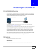
C HAPT ER 1 Introducing the GLC1320G-55 1.1 GLC1320G-55 Overview The GLC1320G-55 is a Gigabit Ethernet Line Card with 20 SFP slot connector slots for fiber-based SFP (mini-GBIC) transceivers (16 for SFP transceiver and 4 for CSFP/SFP). It connects through fiber-optic cables to other Ethernet switches that support fiber connections (like the FSG1100HN, GS2200-8 or FMG3024/3025) located at the subscriber’s premises.
Chapter 1 Introducing the GLC1320G-55 SFP Slots Install SFP (Small Form-factor Pluggable) transceivers to connect to Ethernet switches. Discovery and Dependency Mapping Inventory (DDMI) Discovery and Dependency Mapping Inventory (DDMI) reads the transceiver temperature and voltage. SFP/CSFP Tx Manual Power Disable Manually disables the transfer (Tx) power of individual transceivers.
Chapter 1 Introducing the GLC1320G-55 Loop Guard Loop guard protects against network loops on the edge of you network. Double Tag Mode (DT) For untagged packets, DT adds outer VLAN tag and inner VLAN tags. For tagged packets, DT adds an outer VLAN tag. System Monitoring • System status (link status, rates, statistics counters) • Temperatures, voltage reports and alarms.
Chapter 1 Introducing the GLC1320G-55 Isolation (per-VLAN) Use isolation to block the subscribers in a specific VLAN from sending traffic directly to each other. Packet Filter The GLC1320G-55 supports packet filtering based on protocol. You can configure the GLC1320G-55 to accept all packets, accept PPPoE packets only or block any combination of the following protocols: IP, ARP, DHCP, EAPOL, PPPoE, NetBios or IGMP.
Chapter 1 Introducing the GLC1320G-55 IGMP Message Rate Limiting The GLC1320G-55 can limit how many IGMP message packets a subscriber can send per second. This prevents subscribers from flooding the multicast server. Static Multicast Use static multicast to allow incoming frames based on multicast MAC address(es) that you specify. This feature can be used in conjunction with IGMP snooping to allow multicast MAC address(es) that are not learned by IGMP snooping.
Chapter 1 Introducing the GLC1320G-55 Anti-IP Address Spoofing With DHCP snooping, the GLC1320G-55 records which IP addresses are assigned on each port. The GLC1320G-55 drops packets from a device using a different IP address. Anti-MAC Address Spoofing The GLC1320G-55 checks to make sure the MAC addresses of the devices connected to the subscriber ports are not the same as MAC addresses of devices connected to the Ethernet network.
Chapter 1 Introducing the GLC1320G-55 1.4 Ports and LEDs These are the details of the front panel ports and LEDs. 1.4.1 Ports The following table describes the port labels on the front panel. Table 1 Front Panel Ports LABEL DESCRIPTION CONSOLE For troubleshooting purposes, this mini RJ-11port connects to a computer when the line card is not manageable from the MSC. 1-16 These are slots for SFP transceivers. 17/21-20/24 These are slots for CSFP/SFP transceivers. 1.4.
Chapter 1 Introducing the GLC1320G-55 14 GLC1320G-55 User’s Guide
C HAPT ER 2 Product Specifications This chapter gives details about the line card hardware and features. 2.1 Product Specifications Table 3 Device Specifications Dimensions 390.6 mm (W) x 231.0 mm (D) x 24 mm (H) Device Weight 865g Interfaces • • MAC Address Table Up to 4 K entries Max.
Chapter 2 Product Specifications Table 3 Device Specifications Certifications RoHS & WEEE compliant· ETSI 300-019 · Safety EN60950-1 CSA60950-1 UL60950-1 IEC60950-1 EMC FCC Part 15 Class A EN55022 Class A N55024 Class A ETSI 300 386 Class A Other Features • • • • • • • • • • • • • • • • • • • • • Anti-IP Address Spoofing Anti-MAC Address Spoofing MAC Filtering MAC Count Limiting Hardware-based Multicasting Multicast Group Limit IGMP Message Rate Limiting IEEE 802.1Q VLAN Tagging IEEE 802.
Chapter 2 Product Specifications Table 4 Supported Standards (continued) STANDARD DESCRIPTION RFC 1213 Simple Network Management Protocol (SNMP) RFC 1573 RFC 1757 RFC 2662 RFC 2674 RFC 2863 RFC 3440 RFC 3635 RFC 3636 RFC 1483 Multiprotocol Encapsulation over ATM Adaptation Layer 5 RFC 2131 Dynamic Host Configuration Protocol (DHCP) RFC 2132 RFC 3046 RFC 2138 Remote Authentication Dial In User Service (RADIUS) RFC 2139 RFC 2486 Extensible Authentication Protocol (EAP) RFC 2684 LLC and VC MUX Br
Chapter 2 Product Specifications Figure 3 Console Cable Mini RJ-11 Male Connector Table 5 Console Cable Connector Pin Assignments MINI RJ-11 MALE Pin 2: TXD Pin 3: RXD Pin 4: GND 18 GLC1320G-55 User’s Guide
C HAPT ER 3 Troubleshooting This chapter offers some suggestions to solve problems you might encounter. The potential problems are divided into the following categories. • Power and LEDs • Data Transmission • Local Server • Management and Configuration 3.1 Power and LEDs The SYS or PWR LED does not turn on. Table 6 SYS LED Troubleshooting STEPS CORRECTIVE ACTION 1 Make sure the power wires are properly connected to the power supply and the power supply is operating normally.
Chapter 3 Troubleshooting Table 7 ALM LED Troubleshooting STEPS CORRECTIVE ACTION 2 Ensure that the IES is installed in a well-ventilated area and that normal operation of the fans is not inhibited. Keep the bottom, top and all sides clear of obstructions and away from the exhaust of other equipment. 3 If the voltage levels are outside the allowed range, take a screen shot of the sys monitor status command display and contact your vendor. 3.
Chapter 3 Troubleshooting Table 9 Local Server Troubleshooting STEPS CORRECTIVE ACTION 1 Refer to Section 3.2 on page 20 to make sure that the subscriber is able to transmit to the line card. 2 Make sure the computer behind the Ethernet switch has the correct gateway IP address configured. 3 Check the VLAN configuration (refer to the MSC User’s Guide). 4 Check the cable and connections between the line card and the local server. 5 Try to access another local server.
Chapter 3 Troubleshooting 3 This is an example Xmodem configuration upload using HyperTerminal. Click Transfer, then Send File to display the following screen. Figure 4 Example Xmodem Upload Type the configuration file's location, or click Browse to search for it. Choose the 1K Xmodem protocol. Then click Send. 4 After a successful configuration file upload, type atgo to restart the line card. Bootbase Version: V1.
Chapter 3 Troubleshooting 2 Connect your computer to the console port and use terminal emulation software configured to the following parameters: • VT100 terminal emulation • 9600 bps • No parity, 8 data bits, 1 stop bit • No flow control 3 Pull out the line card and push it back in to restart it and begin a session. 4 When you see the Press any key to enter Debug Mode within 3 seconds message, press a key to enter debug mode.
Chapter 3 Troubleshooting 10 After a successful firmware upload, the line card restarts. The console port speed automatically changes back to 9600 bps when the line card restarts. Bootbase Version: V1.00 | 03/23/2005 16:10:06 FLASH: AMD 32M Hardware Version: Serial Number: RAM: Size = 133120 Kbytes ZyNOS Version: V3.50(ABE.0)b3 | 05/11/2005 11:56:26 Press any key to enter debug mode within 3 seconds. ...........
A PPENDIX A Legal Information Copyright Copyright © 2013 by ZyXEL Communications Corporation. The contents of this publication may not be reproduced in any part or as a whole, transcribed, stored in a retrieval system, translated into any language, or transmitted in any form or by any means, electronic, mechanical, magnetic, optical, chemical, photocopying, manual, or otherwise, without the prior written permission of ZyXEL Communications Corporation. Published by ZyXEL Communications Corporation.
Appendix A Legal Information Taiwanese BSMI (Bureau of Standards, Metrology and Inspection) A Warning: Notices Changes or modifications not expressly approved by the party responsible for compliance could void the user's authority to operate the equipment. This Class A digital apparatus complies with Canadian ICES-003. Cet appareil numérique de la classe A est conforme à la norme NMB-003 du Canada. Viewing Certifications 1 Go to http://www.zyxel.com.
Appendix A Legal Information Registration Register your product online to receive e-mail notices of firmware upgrades and information at www.zyxel.com. Safety Warnings For your safety, be sure to read and follow all warning notices and instructions. • Do NOT use this product near water, for example, in a wet basement or near a swimming pool. • Do NOT expose your device to dampness, dust or corrosive liquids. • Do NOT store things on the device.
Appendix A Legal Information 28 GLC1320G-55 User’s Guide
Index Index A features 7 ALM LED 19 filter, packet 10 filter protocols 10 front panel 12 B I bandwidth control 11 IEEE 802.1Q Tagged VLAN 9 IEEE 802.
Index profile VDSL 8 W protocol filter 10 PWR LED 19 warranty 26 note 26 R X recovering the firmware 22 XMODEM upload 21, 23 registration product 27 xVLAN 8 related documentation 2 S standards, supported 16 static multicast 11 switch lockout 21 SYS LED 19 system error log 11 T Telco-50 connector pin assignments 17 terminal emulation 23 Transparent LAN Service (TLS) 12 U USER Telco-50 connectors 17 V VDSL profile 8 VLAN 20 VLAN Stacking 12 VLAN stacking 12 VT100 23 30 GLC1320G-55 User’s Guid