ZyWALL USG 20/20W Unified Security Gateway Default Login Details LAN Port P2, P3 IP Address https://192.168.1.1 User Name admin Password 1234 www.zyxel.com Version 2.21 Edition 4, 4/2011 www.zyxel.
About This User's Guide About This User's Guide Intended Audience This manual is intended for people who want to want to configure the ZyWALL using the Web Configurator. How To Use This Guide • Read Chapter 1 on page 29 chapter for an overview of features available on the ZyWALL. • Read Chapter 3 on page 43 for web browser requirements and an introduction to the main components, icons and menus in the ZyWALL Web Configurator.
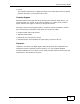
About This User's Guide • Web Configurator Online Help Click the help icon in any screen for help in configuring that screen and supplementary information. • ZyXEL Web Site Please refer to www.zyxel.com for additional support documentation and product certifications. User Guide Feedback Help us help you. Send all User Guide-related comments, questions or suggestions for improvement to the following address, or use e-mail instead. Thank you! The Technical Writing Team, ZyXEL Communications Corp.
About This User's Guide • Forum This contains discussions on ZyXEL products. Learn from others who use ZyXEL products and share your experiences as well. Customer Support Should problems arise that cannot be solved by the methods listed above, you should contact your vendor. If you cannot contact your vendor, then contact a ZyXEL office for the region in which you bought the device. See http://www.zyxel.com/web/contact_us.php for contact information.
Document Conventions Document Conventions Warnings and Notes These are how warnings and notes are shown in this User’s Guide. Warnings tell you about things that could harm you or your device. Note: Notes tell you other important information (for example, other things you may need to configure or helpful tips) or recommendations. Syntax Conventions • The ZyWALL may be referred to as the “ZyWALL”, the “device”, the “system” or the “product” in this User’s Guide.
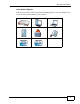
Document Conventions Icons Used in Figures Figures in this User’s Guide may use the following generic icons. The ZyWALL icon is not an exact representation of your device.
Safety Warnings Safety Warnings • Do NOT use this product near water, for example, in a wet basement or near a swimming pool. • Do NOT expose your device to dampness, dust or corrosive liquids. • Do NOT store things on the device. • Do NOT install, use, or service this device during a thunderstorm. There is a remote risk of electric shock from lightning. • Connect ONLY suitable accessories to the device. • Do NOT open the device or unit.
Contents Overview Contents Overview User’s Guide ........................................................................................................................... 27 Introducing the ZyWALL ............................................................................................................ 29 Features and Applications ......................................................................................................... 37 Web Configurator ................................................
Contents Overview Schedules ................................................................................................................................ 567 AAA Server .............................................................................................................................. 573 Authentication Method ............................................................................................................. 583 Certificates ...........................................................
Table of Contents Table of Contents About This User's Guide .......................................................................................................... 3 Document Conventions............................................................................................................ 6 Safety Warnings........................................................................................................................ 8 Contents Overview .......................................................
Table of Contents Chapter 4 Installation Setup Wizard ....................................................................................................... 59 4.1 Installation Setup Wizard Screens ...................................................................................... 59 4.1.1 Internet Access Setup - WAN Interface ..................................................................... 59 4.1.2 Internet Access: Ethernet .........................................................................
Table of Contents 6.5.1 Feature ....................................................................................................................... 95 6.5.2 Licensing Registration ................................................................................................ 96 6.5.3 Interface ..................................................................................................................... 96 6.5.4 Trunks .............................................................................
Table of Contents 7.5 How to Configure User-aware Access Control .................................................................. 120 7.5.1 Set Up User Accounts .............................................................................................. 120 7.5.2 Set Up User Groups ................................................................................................. 121 7.5.3 Set Up User Authentication Using the RADIUS Server ........................................... 122 7.
Table of Contents 8.2.3 The Active Sessions Screen .................................................................................... 173 8.2.4 The VPN Status Screen ........................................................................................... 174 8.2.5 The DHCP Table Screen .......................................................................................... 174 8.2.6 The Number of Login Users Screen .........................................................................
Table of Contents 11.2 Port Role ......................................................................................................................... 220 11.3 Ethernet Summary Screen ............................................................................................... 222 11.3.1 Ethernet Edit .......................................................................................................... 223 11.3.2 Object References ..................................................................
Table of Contents Chapter 14 Routing Protocols................................................................................................................. 313 14.1 Routing Protocols Overview ............................................................................................ 313 14.1.1 What You Can Do in this Chapter .......................................................................... 313 14.1.2 What You Need to Know .......................................................................
Table of Contents 18.2.1 The HTTP Redirect Edit Screen ............................................................................. 350 Chapter 19 ALG ........................................................................................................................................ 351 19.1 ALG Overview ................................................................................................................. 351 19.1.1 What You Can Do in this Chapter ..........................................
Table of Contents 23.1 IPSec VPN Overview ....................................................................................................... 391 23.1.1 What You Can Do in this Chapter .......................................................................... 391 23.1.2 What You Need to Know ........................................................................................ 392 23.1.3 Before You Begin .................................................................................................
Table of Contents 27.6 Uninstalling the ZyWALL SecuExtender .......................................................................... 452 Chapter 28 Bandwidth Management..................................................................................................... 453 28.1 Overview .......................................................................................................................... 453 28.1.1 What You Can Do in this Chapter ......................................................
Table of Contents 31.1 Overview .......................................................................................................................... 513 31.2 Viewing Content Filter Reports ........................................................................................ 513 Chapter 32 Anti-Spam .............................................................................................................................. 521 32.1 Overview ........................................................
Table of Contents 35.1 Overview .......................................................................................................................... 561 35.1.1 What You Can Do in this Chapter .......................................................................... 561 35.1.2 What You Need to Know ........................................................................................ 561 35.2 The Service Summary Screen ................................................................................
Table of Contents 39.1.2 What You Need to Know ........................................................................................ 589 39.1.3 Verifying a Certificate ............................................................................................. 591 39.2 The My Certificates Screen ............................................................................................. 593 39.2.1 The My Certificates Add Screen ..........................................................................
Table of Contents 43.4.2 Time Server Synchronization ................................................................................. 635 43.5 Console Port Speed ......................................................................................................... 636 43.6 DNS Overview ................................................................................................................. 636 43.6.1 DNS Server Address Assignment .................................................................
Table of Contents 44.2 Email Daily Report .......................................................................................................... 679 44.3 Log Setting Screens ....................................................................................................... 681 44.3.1 Log Setting Summary ............................................................................................. 682 44.3.2 Edit System Log Settings ....................................................................
Table of Contents 49.1 Overview .......................................................................................................................... 725 49.1.1 What You Need To Know ....................................................................................... 725 49.2 The Shutdown Screen ..................................................................................................... 725 Chapter 50 Troubleshooting.........................................................................
P ART I User’s Guide 27
CHAPTER 1 Introducing the ZyWALL This chapter gives an overview of the ZyWALL. It explains the front panel ports, LEDs, introduces the management methods, and lists different ways to start or stop the ZyWALL. 1.1 Overview and Key Default Settings The ZyWALL is a comprehensive security device. Its flexible configuration helps network administrators set up the network and enforce security policies efficiently.
Chapter 1 Introducing the ZyWALL 1 Screw the two screws provided with your ZyWALL into the wall 150 mm apart (see the figure in step 2). Use screws with 6 mm ~ 8 mm (0.24" ~ 0.31") wide heads. Do not screw the screws all the way in to the wall; leave a small gap between the head of the screw and the wall. The gap must be big enough for the screw heads to slide into the screw slots and the connection cables to run down the back of the ZyWALL.
Chapter 1 Introducing the ZyWALL USG 20W The ZyWALL should be wall-mounted horizontally. The ZyWALL's side panels with ventilation slots should not be facing up or down as this position is less safe.
Chapter 1 Introducing the ZyWALL 1.3 Front Panel This section introduces the ZyWALL’s front panel. Figure 1 ZyWALL Front Panel ZyWALL USG 20 ZyWALL USG 20W 1.3.1 Front Panel LEDs The following table describes the LEDs. Table 1 Front Panel LEDs LED COLOR STATUS PWR Green DESCRIPTION Off The ZyWALL is turned off. On The ZyWALL is turned on. Breathing The ZyWALL is in power saving mode. SYS Red On There is a hardware component failure.
Chapter 1 Introducing the ZyWALL Table 1 Front Panel LEDs (continued) LED COLOR STATUS DESCRIPTION USB Green Off No device is connected to the ZyWALL’s USB port or the connected device is not supported by the ZyWALL. On A 3G USB card or a USB storage device is connected to the ZyWALL’s USB port. Orange On The ZyWALL is connected to a 3G network through the connected 3G USB card. WLAN (20W Only) Green Off The wireless function is disabled on the ZyWALL.
Chapter 1 Introducing the ZyWALL console port. See the Command Reference Guide for more information about the CLI. Console Port You can use the console port to manage the ZyWALL using CLI commands. See the Command Reference Guide for more information about the CLI. The default settings for the console port are as follows. Table 2 Console Port Default Settings SETTING VALUE Speed 115200 bps Data Bits 8 Parity None Stop Bit 1 Flow Control Off 1.
Chapter 1 Introducing the ZyWALL Table 3 Starting and Stopping the ZyWALL METHOD DESCRIPTION Clicking Maintenance > Shutdown > Shutdown or using the shutdown command Clicking Maintenance > Shutdown > Shutdown or using the shutdown command writes all cached data to the local storage and stops the system processes. Wait for the device to shut down and then manually turn off or remove the power. It does not turn off the power.
Chapter 1 Introducing the ZyWALL 36 ZyWALL USG 20/20W User’s Guide
CHAPTER 2 Features and Applications This chapter introduces the main features and applications of the ZyWALL. 2.1 Features The ZyWALL’s security features include VPN, firewallcontent filtering, ADP (Anomaly Detection and Protection), and certificates. It also provides bandwidth management, NAT, port forwarding, policy routing, DHCP server and many other powerful features. The rest of this section provides more information about the features of the ZyWALL.
Chapter 2 Features and Applications Firewall The ZyWALL’s firewall is a stateful inspection firewall. The ZyWALL restricts access by screening data packets against defined access rules. It can also inspect sessions. For example, traffic from one zone is not allowed unless it is initiated by a computer in another zone first. Anomaly Detection and Prevention (ADP) ADP (Anomaly Detection and Prevention) can detect malicious or suspicious packets and respond instantaneously.
Chapter 2 Features and Applications 2.2 Applications These are some example applications for your ZyWALL. See also Chapter 7 on page 107 for configuration tutorial examples. 2.2.1 VPN Connectivity Set up VPN tunnels with other companies, branch offices, telecommuters, and business travelers to provide secure access to your network. You can also set up additional connections to the Internet to provide better service. Figure 3 Applications: VPN Connectivity 2.2.
Chapter 2 Features and Applications 2.2.2.1 Full Tunnel Mode In full tunnel mode, a virtual connection is created for remote users with private IP addresses in the same subnet as the local network. This allows them to access network resources in the same way as if they were part of the internal network. Figure 4 Network Access Mode: Full Tunnel Mode 192.168.1.100 https;// LAN (192.168.1.
Chapter 2 Features and Applications 2.2.3 User-Aware Access Control Set up security policies that restrict access to sensitive information and shared resources based on the user who is trying to access it.
Chapter 2 Features and Applications 42 ZyWALL USG 20/20W User’s Guide
CHAPTER 3 Web Configurator The ZyWALL Web Configurator allows easy ZyWALL setup and management using an Internet browser. 3.1 Web Configurator Requirements In order to use the Web Configurator, you must • Use Internet Explorer 7 or later, or Firefox 1.5 or later • Allow pop-up windows (blocked by default in Windows XP Service Pack 2) • Enable JavaScripts (enabled by default) • Enable Java permissions (enabled by default) • Enable cookies The recommended screen resolution is 1024 x 768 pixels. 3.
Chapter 3 Web Configurator 2 Open your web browser, and go to http://192.168.1.1. By default, the ZyWALL automatically routes this request to its HTTPS server, and it is recommended to keep this setting. The Login screen appears. Figure 6 Login Screen 3 Type the user name (default: “admin”) and password (default: “1234”). If your account is configured to use an ASAS authentication server, use the OTP (One-Time Password) token to generate a number. Enter it in the One-Time Password field.
Chapter 3 Web Configurator 5 The screen above appears every time you log in using the default user name and default password. If you change the password for the default user account, this screen does not appear anymore. Follow the directions in this screen. If you change the default password, the Login screen (Figure 6 on page 44) appears after you click Apply.
Chapter 3 Web Configurator 3.3.1 Title Bar The title bar provides some icons in the upper right corner. Figure 9 Title Bar The icons provide the following functions. Table 4 Title Bar: Web Configurator Icons LABEL DESCRIPTION Logout Click this to log out of the Web Configurator. Help Click this to open the help page for the current screen. About Click this to display basic information about the ZyWALL. Site Map Click this to see an overview of links to the Web Configurator screens.
Chapter 3 Web Configurator The following table describes labels that can appear in this screen. Table 5 Title Bar: Web Configurator Icons LABEL DESCRIPTION Boot Module This shows the version number of the software that handles the booting process of the ZyWALL. Current Version This shows the firmware version of the ZyWALL. Released Date This shows the date (yyyy-mm-dd) and time (hh:mm:ss) when the firmware is released. OK Click this to close the screen. 3.3.
Chapter 3 Web Configurator 3.3.2.2 Monitor Menu The monitor menu screens display status and statistics information. Table 6 Monitor Menu Screens Summary FOLDER OR LINK TAB FUNCTION System Status Port Statistics Displays packet statistics for each physical port. Interface Status Displays general interface information and packet statistics. Traffic Statistics Collect and display traffic statistics. Session Monitor Displays the status of all current sessions.
Chapter 3 Web Configurator Table 7 Configuration Menu Screens Summary (continued) FOLDER OR LINK Interface Routing TAB FUNCTION Port Role Use this screen to set the ZyWALL’s flexible ports as LAN1 or DMZ. Ethernet Manage Ethernet interfaces and virtual Ethernet interfaces. PPP Create and manage PPPoE and PPTP interfaces. Cellular Configure a cellular Internet connection for an installed 3G card. WLAN (For USG 20W only) Configure settings for an installed wireless LAN card.
Chapter 3 Web Configurator Table 7 Configuration Menu Screens Summary (continued) FOLDER OR LINK TAB FUNCTION General Display and manage ADP bindings. Profile Create and manage ADP profiles. General Create and manage content filter policies. Filter Profile Create and manage the detailed filtering rules for content filtering policies. General Turn anti-spam on or off and manage anti-spam policies.
Chapter 3 Web Configurator Table 7 Configuration Menu Screens Summary (continued) FOLDER OR LINK TAB Endpoint Security FUNCTION Create Endpoint Security (EPS) objects. System Host Name Configure the system and domain name for the ZyWALL. USB Storage Configure the settings for the connected USB devices. Date/Time Configure the current date, time, and time zone in the ZyWALL. Console Speed Set the console speed. DNS Configure the DNS server and address records for the ZyWALL.
Chapter 3 Web Configurator Table 8 Maintenance Menu Screens Summary (continued) FOLDER OR LINK Diagnostics Packet Flow Explore TAB FUNCTION Diagnostic Collect diagnostic information. Packet Capture Capture packets for analysis. Routing Status View a clear picture on how the ZyWALL determines where to route a packet and check the related settings. SNAT Status View a clear picture on how the ZyWALL converts a packet’s source IP address and check the related settings. Reboot Restart the ZyWALL.
Chapter 3 Web Configurator 3.3.3.2 Site Map Click Site MAP to see an overview of links to the Web Configurator screens. Click a screen’s link to go to that screen. Figure 13 Site Map 3.3.3.3 Object Reference Click Object Reference to open the Object Reference screen. Select the type of object and the individual object and click Refresh to show which configuration settings reference the object.
Chapter 3 Web Configurator The fields vary with the type of object. The following table describes labels that can appear in this screen. Table 9 Object References LABEL DESCRIPTION Object Name This identifies the object for which the configuration settings that use it are displayed. Click the object’s name to display the object’s configuration screen in the main window. # This field is a sequential value, and it is not associated with any entry.
Chapter 3 Web Configurator 3.3.4.1 Manipulating Table Display Here are some of the ways you can manipulate the Web Configurator tables. 1 Click a column heading to sort the table’s entries according to that column’s criteria. Figure 16 Sorting Table Entries by a Column’s Criteria 2 Click the down arrow next to a column heading for more options about how to display the entries. The options available vary depending on the type of fields in the column.
Chapter 3 Web Configurator 3 Select a column heading cell’s right border and drag to re-size the column. Figure 18 Resizing a Table Column 4 Select a column heading and drag and drop it to change the column order. A green check mark displays next to the column’s title when you drag the column to a valid new location. Figure 19 Changing the Column Order 5 Use the icons and fields at the bottom of the table to navigate to different pages of entries and control how many entries display at a time.
Chapter 3 Web Configurator 3.3.4.2 Working with Table Entries The tables have icons for working with table entries. A sample is shown next. You can often use the [Shift] or [Ctrl] key to select multiple entries to remove, activate, or deactivate. Figure 21 Common Table Icons Here are descriptions for the most common table icons. Table 10 Common Table Icons LABEL DESCRIPTION Add Click this to create a new entry.
Chapter 3 Web Configurator you can also use the [Shift] or [Ctrl] key to select multiple entries, and then use the arrow button to move them to the other list.
CHAPTER 4 Installation Setup Wizard 4.1 Installation Setup Wizard Screens If you log into the Web Configurator when the ZyWALL is using its default configuration, the first Installation Setup Wizard screen displays. This wizard helps you configure Internet connection settings and activate subscription services. This chapter provides information on configuring the Web Configurator's installation setup wizard. See the feature-specific chapters in this User’s Guide for background information.
Chapter 4 Installation Setup Wizard The screens vary depending on the encapsulation type. Refer to information provided by your ISP to know what to enter in each field. Leave a field blank if you don’t have that information. Note: Enter the Internet access information exactly as your ISP gave it to you. Figure 24 Internet Access: Step 1 • Encapsulation: Choose the Ethernet option when the WAN port is used as a regular Ethernet.
Chapter 4 Installation Setup Wizard • IP Address: Enter your (static) public IP address. Auto displays if you selected Auto as the IP Address Assignment in the previous screen. The following fields display if you selected static IP address assignment. • IP Subnet Mask: Enter the subnet mask for this WAN connection's IP address. • Gateway IP Address: Enter the IP address of the router through which this WAN connection will send traffic (the default gateway).
Chapter 4 Installation Setup Wizard • CHAP/PAP - Your ZyWALL accepts either CHAP or PAP when requested by the remote node. • CHAP - Your ZyWALL accepts CHAP only. • PAP - Your ZyWALL accepts PAP only. • MSCHAP - Your ZyWALL accepts MSCHAP only. • MSCHAP-V2 - Your ZyWALL accepts MSCHAP-V2 only. • Type the User Name given to you by your ISP. You can use alphanumeric and _@$./ characters, and it can be up to 31 characters long. • Type the Password associated with the user name.
Chapter 4 Installation Setup Wizard 4.1.4 Internet Access: PPTP Note: Enter the Internet access information exactly as given to you by your ISP. Figure 27 Internet Access: PPTP Encapsulation 4.1.5 ISP Parameters • Authentication Type - Select an authentication protocol for outgoing calls. Options are: • CHAP/PAP - Your ZyWALL accepts either CHAP or PAP when requested by the remote node. • CHAP - Your ZyWALL accepts CHAP only. • PAP - Your ZyWALL accepts PAP only.
Chapter 4 Installation Setup Wizard • Select Nailed-Up if you do not want the connection to time out. Otherwise, type the Idle Timeout in seconds that elapses before the router automatically disconnects from the PPTP server. 4.1.5.1 PPTP Configuration • Base Interface: This identifies the Ethernet interface you configure to connect with a modem or router. • Type a Base IP Address (static) assigned to you by your ISP. • Type the IP Subnet Mask assigned to you by your ISP (if given).
Chapter 4 Installation Setup Wizard 4.1.6 Internet Access - Finish You have set up your ZyWALL to access the Internet. After configuring the WAN interface, a screen displays with your settings. If they are not correct, click Back. Figure 28 Internet Access: Ethernet Encapsulation Note: If you have not already done so, you can register your ZyWALL with myZyXEL.com and activate trials of services like Content Filter. Click Next and use the following screen to perform a basic registration (see Section 4.
Chapter 4 Installation Setup Wizard Use the Registration > Service screen to update your service subscription status. Figure 29 Registration • Select new myZyXEL.com account if you haven’t created an account at myZyXEL.com, select this option and configure the following fields to create an account and register your ZyWALL. • Select existing myZyXEL.com account if you already have an account at myZyXEL.com and enter your user name and password in the fields below to register your ZyWALL.
Chapter 4 Installation Setup Wizard • Trial Service Activation: You can try a trial service subscription. The trial period starts the day you activate the trial. After the trial expires, you can buy an iCard and enter the license key in the Registration > Service screen to extend the service.
Chapter 4 Installation Setup Wizard 68 ZyWALL USG 20/20W User’s Guide
CHAPTER 5 Quick Setup 5.1 Quick Setup Overview The Web Configurator's quick setup wizards help you configure Internet and VPN connection settings. This chapter provides information on configuring the quick setup screens in the Web Configurator. See the feature-specific chapters in this User’s Guide for background information. In the Web Configurator, click Configuration > Quick Setup to open the first Quick Setup screen.
Chapter 5 Quick Setup 5.2 WAN Interface Quick Setup Click WAN Interface in the main Quick Setup screen to open the WAN Interface Quick Setup Wizard Welcome screen. Use these screens to configure an interface to connect to the internet. Click Next. Figure 32 WAN Interface Quick Setup Wizard 5.2.1 Choose an Ethernet Interface Select the Ethernet interface that you want to configure for a WAN connection and click Next. Figure 33 Choose an Ethernet Interface 5.2.
Chapter 5 Quick Setup Otherwise, choose PPPoE or PPTP for a dial-up connection according to the information from your ISP. Figure 34 WAN Interface Setup: Step 2 The screens vary depending on what encapsulation type you use. Refer to information provided by your ISP to know what to enter in each field. Leave a field blank if you don’t have that information. Note: Enter the Internet access information exactly as your ISP gave it to you. 5.2.
Chapter 5 Quick Setup • IP Address Assignment: Select Auto If your ISP did not assign you a fixed IP address. Select Static If the ISP assigned a fixed IP address. 5.2.4 WAN and ISP Connection Settings Use this screen to configure the ISP and WAN interface settings. This screen is read-only if you set the IP Address Assignment to Static. Note: Enter the Internet access information exactly as your ISP gave it to you.
Chapter 5 Quick Setup Table 11 WAN and ISP Connection Settings (continued) LABEL DESCRIPTION Authentication Use the drop-down list box to select an authentication protocol for Type outgoing calls. Options are: CHAP/PAP - Your ZyWALL accepts either CHAP or PAP when requested by this remote node. CHAP - Your ZyWALL accepts CHAP only. PAP - Your ZyWALL accepts PAP only. MSCHAP - Your ZyWALL accepts MSCHAP only. MSCHAP-V2 - Your ZyWALL accepts MSCHAP-V2 only.
Chapter 5 Quick Setup Table 11 WAN and ISP Connection Settings (continued) LABEL First DNS Server Second DNS Server DESCRIPTION These fields only display for an interface with a static IP address. Enter the DNS server IP address(es) in the field(s) to the right. Leave the field as 0.0.0.0 if you do not want to configure DNS servers. If you do not configure a DNS server, you must know the IP address of a machine in order to access it.
Chapter 5 Quick Setup Table 12 Interface Wizard: Summary WAN LABEL DESCRIPTION User Name This is the user name given to you by your ISP. Nailed-Up If No displays the connection will not time out. Yes means the ZyWALL uses the idle timeout. Idle Timeout This is how many seconds the connection can be idle before the router automatically disconnects from the PPPoE server. 0 means no timeout. Connection ID If you specified a connection ID, it displays here.
Chapter 5 Quick Setup 5.4 VPN Setup Wizard: Wizard Type A VPN (Virtual Private Network) tunnel is a secure connection to another computer or network. Use this screen to select which type of VPN connection you want to configure. Figure 39 VPN Setup Wizard: Wizard Type Express: Use this wizard to create a VPN connection with another ZLD-based ZyWALL using a pre-shared key and default security settings. Advanced: Use this wizard to configure detailed VPN security settings such as using certificates.
Chapter 5 Quick Setup 5.5 VPN Express Wizard - Scenario Click the Express radio button as shown in Figure 39 on page 76 to display the following screen. Figure 40 VPN Express Wizard: Step 2 Rule Name: Type the name used to identify this VPN connection (and VPN gateway). You may use 1-31 alphanumeric characters, underscores (_), or dashes (-), but the first character cannot be a number. This value is case-sensitive. Select the scenario that best describes your intended VPN connection.
Chapter 5 Quick Setup 5.5.1 VPN Express Wizard - Configuration Figure 41 VPN Express Wizard: Step 3 • Secure Gateway: If Any displays in this field, it is not configurable for the chosen scenario. If this field is configurable, enter the WAN IP address or domain name of the remote IPSec device (secure gateway) to identify the remote IPSec router by its IP address or a domain name. Use 0.0.0.0 if the remote IPSec router has a dynamic WAN IP address. • Pre-Shared Key: Type the password.
Chapter 5 Quick Setup 5.5.2 VPN Express Wizard - Summary This screen provides a read-only summary of the VPN tunnel’s configuration and also commands that you can copy and paste into another ZLD-based ZyWALL’s command line interface to configure it. Figure 42 VPN Express Wizard: Step 4 • Rule Name: Identifies the VPN gateway policy. • Secure Gateway: IP address or domain name of the remote IPSec device. If this field displays Any, only the remote IPSec device can initiate the VPN connection.
Chapter 5 Quick Setup 5.5.3 VPN Express Wizard - Finish Now you can use the VPN tunnel. Figure 43 VPN Express Wizard: Step 6 Note: If you have not already done so, use the myZyXEL.com link and register your ZyWALL with myZyXEL.com and activate trials of services like Content Filter. Click Close to exit the wizard.
Chapter 5 Quick Setup 5.5.4 VPN Advanced Wizard - Scenario Click the Advanced radio button as shown in Figure 39 on page 76 to display the following screen. Figure 44 VPN Advanced Wizard: Scenario Rule Name: Type the name used to identify this VPN connection (and VPN gateway). You may use 1-31 alphanumeric characters, underscores (_), or dashes (-), but the first character cannot be a number. This value is case-sensitive. Select the scenario that best describes your intended VPN connection.
Chapter 5 Quick Setup • Remote Access (Client Role) - Choose this to connect to an IPSec server. This ZyWALL is the client (dial-in user) and can initiate the VPN tunnel. 5.5.5 VPN Advanced Wizard - Phase 1 Settings There are two phases to every IKE (Internet Key Exchange) negotiation – phase 1 (Authentication) and phase 2 (Key Exchange). A phase 1 exchange establishes an IKE SA (Security Association).
Chapter 5 Quick Setup that uses a 168-bit key. As a result, 3DES is more secure than DES. It also requires more processing power, resulting in increased latency and decreased throughput. AES128 uses a 128-bit key and is faster than 3DES. AES192 uses a 192-bit key and AES256 uses a 256-bit key. • Authentication Algorithm: MD5 gives minimal security. SHA-1 gives higher security. MD5 (Message Digest 5) and SHA1 (Secure Hash Algorithm) are hash algorithms used to authenticate packet data.
Chapter 5 Quick Setup • Active Protocol: ESP is compatible with NAT, AH is not. • Encapsulation: Tunnel is compatible with NAT, Transport is not. • Encryption Algorithm: 3DES and AES use encryption. The longer the AES key, the higher the security (this may affect throughput). Null uses no encryption. • Authentication Algorithm: MD5 gives minimal security. SHA-1 gives higher security. MD5 (Message Digest 5) and SHA1 (Secure Hash Algorithm) are hash algorithms used to authenticate packet data.
Chapter 5 Quick Setup 5.5.7 VPN Advanced Wizard - Summary This is a read-only summary of the VPN tunnel settings. Figure 47 VPN Advanced Wizard: Step 5 • Rule Name: Identifies the VPN connection (and the VPN gateway). • Secure Gateway: IP address or domain name of the remote IPSec device. • Pre-Shared Key: VPN tunnel password. • Certificate: The certificate the ZyWALL uses to identify itself when setting up the VPN tunnel.
Chapter 5 Quick Setup 5.5.8 VPN Advanced Wizard - Finish Now you can use the VPN tunnel. Figure 48 VPN Wizard: Step 6: Advanced Note: If you have not already done so, you can register your ZyWALL with myZyXEL.com and activate trials of services like Content Filter. Click Close to exit the wizard.
CHAPTER 6 Configuration Basics This information is provided to help you configure the ZyWALL effectively. Some of it is helpful when you are just getting started. Some of it is provided for your reference when you configure various features in the ZyWALL. • Section 6.1 on page 87 introduces the ZyWALL’s object-based configuration. • Section 6.2 on page 88 introduces zones, interfaces, and port groups. • Section 6.3 on page 91 introduces some terminology and organization for the ZyWALL. • Section 6.
Chapter 6 Configuration Basics change an Ethernet interface’s IP address, the ZyWALL automatically updates the rules or settings that use the interface-based, LAN subnet address object. You can use the Configuration > Objects screens to create objects before you configure features that use them. If you are in a screen that uses objects, you can also usually select Create new Object to be able to configure a new object. For a list of common objects, see Section 6.6 on page 103.
Chapter 6 Configuration Basics 6.2.1 Interface Types There are many types of interfaces in the ZyWALL. In addition to being used in various features, interfaces also describe the network that is directly connected to the ZyWALL. • Ethernet interfaces are the foundation for defining other interfaces and network policies. You also configure RIP and OSPF in these interfaces. • Port groups create a hardware connection between physical ports at the layer2 (data link, MAC address) level.
Chapter 6 Configuration Basics 6.2.2 Default Interface and Zone Configuration This section introduces the ZyWALL’s default zone member physical interfaces and the default configuration of those interfaces. The following figure uses letters to denote public IP addresses or part of a private IP address.
Chapter 6 Configuration Basics • The DMZ zone contains the dmz interface (physical port P6). The DMZ zone has servers that are available to the public. The dmz interface uses private IP address 192.168.3.1 and the connected devices use private IP addresses in the 192.168.3.2 to 192.168.3.254 range. 6.3 Terminology in the ZyWALL This section highlights some terminology or organization for ZLD-based ZyWALLs.
Chapter 6 Configuration Basics Traffic in > Defragmentation > Destination NAT > Routing > Stateful Firewall > ADP > Application Classification > Content Filter > Anti-Spam > SNAT > Bandwidth Management > Fragmentation > Traffic Out. Figure 51 Packet Flow The packet flow is as follows: • Automatic SNAT and WAN trunk routing for traffic going from internal to external interfaces (you don’t need to configure anything to all LAN to WAN traffic).
Chapter 6 Configuration Basics of the sections, the ZyWALL stops checking the packets against the routing table and moves on to the other checks, for example the firewall check. Figure 52 Routing Table Checking Flow 1 Direct-connected Subnets: The ZyWALL first checks to see if the packets are destined for an address in the same subnet as one of the ZyWALL’s interfaces.
Chapter 6 Configuration Basics 4 Auto VPN Policy: The ZyWALL automatically creates these routing entries for the VPN rules. Disabling the IPSec VPN feature’s Use Policy Route to control dynamic IPSec rules option moves the routes for dynamic IPSec rules up above the policy routes (see Section 23.2 on page 394). 5 Static and Dynamic Routes: This section contains the user-configured static routes and the dynamic routing information learned from other routers through RIP and OSPF.
Chapter 6 Configuration Basics 4 SNAT is also now performed by default and included in the NAT table. 6.5 Feature Configuration Overview This section provides information about configuring the main features in the ZyWALL. The features are listed in the same sequence as the menu item(s) in the Web Configurator. Each feature description is organized as shown below. 6.5.1 Feature This provides a brief description. See the appropriate chapter(s) in this User’s Guide for more information about any feature.
Chapter 6 Configuration Basics 6.5.2 Licensing Registration Use these screens to register your ZyWALL and subscribe to services like more SSL VPN tunnels, and content filtering. You must have Internet access to myZyXEL.com. MENU ITEM(S) Configuration > Licensing > Registration PREREQUISITES Internet access to myZyXEL.com 6.5.3 Interface See Section 6.2 on page 88 for background information. Note: When you create an interface, there is no security applied on it until you assign it to a zone.
Chapter 6 Configuration Basics and general NAT on the source address. You have to set up the criteria, next-hops, and NAT settings first.
Chapter 6 Configuration Basics 6.5.6 Static Routes Use static routes to tell the ZyWALL about networks not directly connected to the ZyWALL. MENU ITEM(S) Configuration > Network > Routing > Static Route PREREQUISITES Interfaces 6.5.7 Zones See Section 6.2 on page 88 for background information. A zone is a group of interfaces and VPN tunnels. The ZyWALL uses zones, not interfaces, in many security settings, such as firewall rules and remote management. Zones cannot overlap.
Chapter 6 Configuration Basics PREREQUISITES Interfaces, addresses (HOST) Example: Suppose you have an FTP server with a private IP address connected to a DMZ port. You could configure a NAT rule to forwards FTP sessions from the WAN to the DMZ. 1 Click Configuration > Network > NAT to configure the NAT entry. Add an entry. 2 Name the entry. 3 Select the WAN interface that the FTP traffic is to come in through. 4 Specify the public WAN IP address where the ZyWALL will receive the FTP packets.
Chapter 6 Configuration Basics 5 Specify the IP address of the HTTP proxy server. 6 Specify the port number to use for the HTTP traffic that you forward to the proxy server. 6.5.11 ALG The ZyWALL’s Application Layer Gateway (ALG) allows VoIP and FTP applications to go through NAT on the ZyWALL. You can also specify additional signaling port numbers. MENU ITEM(S) Configuration > Network > ALG 6.5.12 Auth. Policy Use authentication policies to control who can access the network.
Chapter 6 Configuration Basics 1 Create a VoIP service object for UDP port 5060 traffic (Configuration > Object > Service). 2 Create an address object for the VoIP server (Configuration > Object > Address). 3 Click Configuration > Firewall to go to the firewall configuration. 4 Select from the DMZ zone to the LAN1 zone, and add a firewall rule using the items you have configured. • You don’t need to specify the schedule or the user.
Chapter 6 Configuration Basics 6.5.16 Bandwidth Management Use bandwidth management (BWM) to configure a BWM rule for a specific IP address, destination port or IP range and specify allowed amounts of bandwidth and priorities. MENU ITEM(S) Configuration > BWM PREREQUISITES Zones Examples: Suppose you want to give a user named Bob FTP access but with a limited download speed of 200 kbps from LAN (FTP client) to WAN (FTP server). 1 Create user account for Bob. 2 Click BWM > Add New Policy.
Chapter 6 Configuration Basics 2 Create a schedule for the work day (Configuration > Object > Schedule). 3 Click Configuration > Anti-X > Content Filter > Filter Profile. Click the Add icon to go to the screen where you can configure a category-based profile. 4 Name the profile and enable it. 5 Enable the external web filter service.
Chapter 6 Configuration Basics The following table introduces the objects. You can also use this table when you want to delete an object because you have to delete references to the object first. Table 16 Objects Overview OBJECT WHERE USED user/group See the User/Group section on page 104 for details on users and user groups.
Chapter 6 Configuration Basics WHERE USED Policy routes, firewall, content filter, user groups, VPN 6.7 System This section introduces some of the management features in the ZyWALL. Use Host Name to configure the system and domain name for the ZyWALL. Use Date/Time to configure the current date, time, and time zone in the ZyWALL. Use Console Speed to set the console speed. Use Language to select a language for the Web Configurator screens. 6.7.
Chapter 6 Configuration Basics 6.7.3 File Manager Use these screens to upload, download, delete, or run scripts of CLI commands. You can manage • Configuration files. Use configuration files to back up and restore the complete configuration of the ZyWALL. You can store multiple configuration files in the ZyWALL and switch between them without restarting. • Shell scripts. Use shell scripts to run a series of CLI commands.
CHAPTER 7 Tutorials Here are examples of using the Web Configurator to set up features in the ZyWALL. Note: The tutorials featured here require a basic understanding of connecting to and using the Web Configurator, see Chapter 3 on page 43 for details. For field descriptions of individual screens, see Technical Reference on page 163. 7.
Chapter 7 Tutorials • Convert P5 (lan2) into a dmz interface. This dmz interface is used for a protected local network. It uses IP address 192.168.4.1 and has a DHCP server. Add it to the LAN zone so all of the LAN zone’s security policies apply to it. Figure 54 Ethernet Interface, Port Roles, and Zone Configuration Example 7.1.1 Configure a WAN Ethernet Interface You need to assign the ZyWALL’s wan1 interface a static IP address of 1.2.3.4.
Chapter 7 Tutorials Click Configuration > Network > Interface > Ethernet and double-click the wan1 interface’s entry. Select Use Fixed IP Address and configure the IP address, subnet mask, and default gateway settings and click OK. Figure 55 Configuration > Network > Interface > Ethernet > Edit wan1 7.1.2 Configure Port Roles Here is how to convert port P5 from the lan2 interface and add it to the dmz interface. 1 Click Configuration > Network > Interface > Role.
Chapter 7 Tutorials 1 Click Configuration > Network > Interface > Ethernet and double-click the lan2 interface’s entry. The Interface Type should be internal. Set the IP Address to 192.168.4.1 and the Subnet Mask to 255.255.255.0. Set DHCP to DHCP Server and click OK. Figure 57 Configuration > Network > Interface > Ethernet > Edit lan2 7.1.4 Configure Zones Do the following to create a VPN zone. 1 110 Click Configuration > Network > Zone and then the Add icon.
Chapter 7 Tutorials 2 Enter VPN as the name, select WIZ_VPN_Connection and move it to the Member box and click OK. Figure 58 Configuration > Network > Zone > WAN Edit 7.2 How to Configure a Cellular Interface Use 3G cards for cellular WAN (Internet) connections. Table 229 on page 741 lists the compatible 3G devices. In this example you connect the 3G USB card before you configure the cellular interfaces but is also possible to reverse the sequence. 1 Make sure the 3G device’s SIM card is installed.
Chapter 7 Tutorials 4 Enable the interface and add it to a zone. It is highly recommended that you set the Zone to WAN to apply your WAN zone security settings to this 3G connection. Leaving Zone set to none has the ZyWALL not apply any security settings to the 3G connection. Enter the PIN Code provided by the cellular 3G service provider (0000 in this example). Figure 60 Configuration > Network > Interface > Cellular > Edit Note: The Network Selection is set to Auto by default.
Chapter 7 Tutorials 6 The ZyWALL automatically adds the cellular interface to the system default WAN trunk. If the ZyWALL is using a user-configured trunk as its default trunk and you want this cellular interface to be part of it, use the Trunk screens to add it. This way the ZyWALL can automatically balance the traffic load amongst the available WAN connections to enhance overall network throughput. Plus, if a WAN connection goes down, the ZyWALL still sends traffic through the remaining WAN connections.
Chapter 7 Tutorials 1 Click Configuration > Network > Interface > Ethernet and double-click the wan1 entry. Enter the available bandwidth (1000 kbps) in the Egress Bandwidth field. Click OK. Figure 63 Configuration > Network > Interface > Ethernet > Edit (wan1) 2 Go to Configuration > Network > Interface > Cellular. Double-click the cellular1 entry and set the egress bandwidth for cellular1 to 512 Kbps. 7.3.2 Configure the WAN Trunk 1 114 Click Configuration > Network > Interface > Trunk.
Chapter 7 Tutorials 2 Name the trunk and set the Load Balancing Algorithm field to Weighted Round Robin. Add wan1 and enter 2 in the Weight column. Add cellular1 and enter 1 in the Weight column. Click OK.
Chapter 7 Tutorials 3 Select the trunk as the default trunk and click Apply. Figure 65 Configuration > Network > Interface > Trunk 7.4 How to Set Up an IPSec VPN Tunnel This example shows how to use the IPSec VPN configuration screens to create the following VPN tunnel, see Section 5.4 on page 76 for details on the VPN quick setup wizard. Figure 66 VPN Example LAN LAN 1.2.3.4 192.168.1.0/24 116 2.2.2.2 172.16.1.
Chapter 7 Tutorials In this example, the ZyWALL is router X (1.2.3.4), and the remote IPSec router is router Y (2.2.2.2). Create the VPN tunnel between ZyWALL X’s LAN subnet (192.168.1.0/24) and the LAN subnet behind peer IPSec router Y (172.16.1.0/ 24). 7.4.1 Set Up the VPN Gateway The VPN gateway manages the IKE SA. You do not have to set up any other objects before you configure the VPN gateway because this VPN tunnel does not use any certificates or extended authentication.
Chapter 7 Tutorials 7.4.2 Set Up the VPN Connection The VPN connection manages the IPSec SA. You have to set up the address objects for the local network and remote network before you can set up the VPN connection. 1 Click Configuration > Object > Address. Click the Add icon. 2 Give the new address object a name (“VPN_REMOTE_SUBNET”), change the Address Type to SUBNET. Set up the Network field to 172.16.1.0 and the Netmask to 255.255.255.0. Click OK.
Chapter 7 Tutorials 4 Enable the VPN connection and name it (“VPN_CONN_EXAMPLE”). Under VPN Gateway select Site-to-site and the VPN gateway (VPN_GW_EXAMPLE). Under Policy, select LAN1_SUBNET for the local network and VPN_REMOTE_SUBNET for the remote. Click OK. Figure 69 Configuration > VPN > IPSec VPN > VPN Connection > Add 5 Now set up the VPN settings on the peer IPSec router and try to establish the VPN tunnel.
Chapter 7 Tutorials 7.5 How to Configure User-aware Access Control You can configure many policies and security settings for specific users or groups of users. This is illustrated in the following example, where you will set up the following policies. This is a simple example that does not include priorities for different types of traffic. See Bandwidth Management on page 445 for more on bandwidth management.
Chapter 7 Tutorials 2 Enter the same user name that is used in the RADIUS server, and set the User Type to ext-user because this user account is authenticated by an external server. Click OK. Figure 70 Configuration > Object > User/Group > User > Add 3 Repeat this process to set up the remaining user accounts. 7.5.2 Set Up User Groups Set up the user groups and assign the users to the user groups. 1 Click Configuration > Object > User/Group > Group. Click the Add icon.
Chapter 7 Tutorials 2 Enter the name of the group that is used in the example in Table 18 on page 120. In this example, it is “Finance”. Then, select User/Leo and click the right arrow to move him to the Member list. This example only has one member in this group, so click OK. Of course you could add more members later. Figure 71 Configuration > Object > User/Group > Group > Add 3 Repeat this process to set up the remaining user groups. 7.5.
Chapter 7 Tutorials 1 Click Configuration > Object > AAA Server > RADIUS. Double-click the radius entry. Configure the RADIUS server’s address authentication port (1812 if you were not told otherwise), key, and click Apply. Figure 72 Configuration > Object > AAA Server > RADIUS > Add 2 Click Configuration > Object > Auth. method. Double-click the default entry. Click the Add icon. Select group radius because the ZyWALL should use the specified RADIUS server for authentication. Click OK.
Chapter 7 Tutorials Note: The users will have to log in using the Web Configurator login screen before they can use HTTP or MSN. Figure 74 Configuration > Object > User/Group > Setting > Add (Force User Authentication Policy) When the users try to browse the web (or use any HTTP/HTTPS application), the Login screen appears. They have to log in using the user name and password in the RADIUS server. 7.
Chapter 7 Tutorials 1 Click Configuration > Object > AAA Server > RADIUS. Double-click the radius entry. Besides configuring the RADIUS server’s address, authentication port, and key; set the Group Membership Attribute field to the attribute that the ZyWALL is to check to determine to which group a user belongs. This example uses Class. This attribute’s value is called a group identifier; it determines to which group a user belongs. In this example the values are Finance, Engineer, Sales, and Boss.
Chapter 7 Tutorials 2 Now you add ext-group-user user objects to identify groups based on the group identifier values. Set up one user account for each group of user accounts in the RADIUS server. Click Configuration > Object > User/Group > User. Click the Add icon. Enter a user name and set the User Type to ext-group-user. In the Group Identifier field, enter Finance, Engineer, Sales, or Boss and set the Associated AAA Server Object to radius.
Chapter 7 Tutorials • Select Endpoint must have Personal Firewall installed and move the Kaspersky Internet Security entries to the allowed list (you can double-click an entry to move it). • Select Endpoint must have Anti-Virus software installed and move the Kaspersky Internet Security and Kaspersky Anti-Virus anti-virus software entries to the allowed list. The following figure shows the configuration screen example.
Chapter 7 Tutorials Repeat as needed to create endpoint security objects for other Windows operating system versions. 7.7.2 Configure the Authentication Policy Click Configuration > Auth. Policy > Add to open the Endpoint Security Edit screen. Use this screen to configure an authentication policy to use endpoint security objects. • Enable the policy and name it.
Chapter 7 Tutorials 4 Turn on authentication policy and click Apply. Figure 79 Configuration > Auth. Policy The following figure shows an error message example when a user’s computer does not meet an endpoint security object’s requirements. Click Close to return to the login screen. Figure 80 Example: Endpoint Security Error Message 7.
Chapter 7 Tutorials user access (logging into SSL VPN for example). See Chapter 43 on page 629 for more on service control. The To-ZyWALL firewall rules apply to any kind of HTTP or HTTPS connection to the ZyWALL. They do not distinguish between administrator management access and user access. If you configure service control to allow management or user HTTP or HTTPS access, make sure the firewall is not configured to block that access. 7.8.
Chapter 7 Tutorials 4 Select the new rule and click the Add icon. Figure 83 Configuration > System > WWW (First Example Admin Service Rule Configured) 5 In the Zone field select ALL and set the Action to Deny. Click OK.
Chapter 7 Tutorials 6 Click Apply. Figure 85 Configuration > System > WWW (Second Example Admin Service Rule Configured) Now administrator access to the Web Configurator can only come from the LAN1 zone. Non-admin users can still use HTTPS to log into the ZyWALL from any of the ZyWALL’s zones (to use SSL VPN for example). 7.9 How to Allow Incoming H.323 Peer-to-peer Calls Suppose you have a H.323 device on the LAN1 for VoIP calls and you want it to be able to receive peer-to-peer calls from the WAN.
Chapter 7 Tutorials for wan1 IP address 10.0.0.8 to a H.323 device located on the LAN and using IP address 192.168.1.56. Figure 86 WAN to LAN H.323 Peer-to-peer Calls Example 192.168.1.56 10.0.0.8 7.9.1 Turn On the ALG Click Configuration > Network > ALG. Select Enable H.323 ALG and Enable H.323 transformations and click Apply. Figure 87 Configuration > Network > ALG 7.9.2 Set Up a NAT Policy For H.323 In this example, you need a NAT policy to forward H.
Chapter 7 Tutorials 1 Use Configuration > Object > Address > Add to create an address object for the public WAN IP address (called WAN_IP-for-H323 here). Then use it again to create an address object for the H.323 device’s private LAN1 IP address (called LAN_H323 here).
Chapter 7 Tutorials 2 Click Configuration > Network > NAT > Add. Configure a name for the rule (WAN-LAN_H323 here). You want the LAN H.323 device to receive peer-to-peer calls from the WAN and also be able to initiate calls to the WAN so you set the Classification to NAT 1:1. Set the Incoming Interface to wan1. Set the Original IP to the WAN address object (WAN_IP-for-H323). Set the Mapped IP to the H.323 device’s LAN1 IP address object (LAN_H323).
Chapter 7 Tutorials 1 Click Configuration > Firewall > Add. In the From field select WAN. In the To field select LAN1. Configure a name for the rule (WAN-to-LAN_H323 here). Set the Destination to the H.323 device’s LAN1 IP address object (LAN_H323). LAN_H323 is the destination because the ZyWALL applies NAT to traffic before applying the firewall rule. Set the Service to H.323. Click OK. Figure 90 Configuration > Firewall > Add 7.
Chapter 7 Tutorials 7.10.1 Create the Address Objects Use Configuration > Object > Address > Add to create the address objects. 1 Create a host address object named DMZ_HTTP for the HTTP server’s private IP address of 192.168.3.7. Figure 92 Creating the Address Object for the HTTP Server’s Private IP Address 2 Create a host address object named Public_HTTP_Server_IP for thepublic WAN IP address 1.1.1.1. Figure 93 Creating the Address Object for thePublic IP Address 7.10.
Chapter 7 Tutorials • Keep Enable NAT Loopback selected to allow users connected to other interfaces to access the HTTP server (see NAT Loopback on page 343 for details). Figure 94 Creating the NAT Entry 7.10.3 Set Up a Firewall Rule The firewall blocks traffic from the WAN zone to the DMZ zone by default so you need to create a firewall rule to allow the public to send HTTP traffic to IP address 1.1.1.1 in order to access the HTTP server. If a domain name is registered for IP address 1.1.1.
Chapter 7 Tutorials 1 Click Configuration > Firewall > Add. Set the From field as WAN and the To field as DMZ. Set the Destination to the HTTP server’s DMZ IP address object (DMZ_HTTP). DMZ_HTTP is the destination because the ZyWALL applies NAT to traffic before applying the firewall rule. Set the Access field to allow and the Service to HTTP, and click OK. Figure 95 Configuration > Firewall > Add 7.
Chapter 7 Tutorials address 1.1.1.2 that you will use on the wan1 interface and map to the IPPBX’s private IP address of 192.168.3.7. The local SIP clients are on the LAN.
Chapter 7 Tutorials 7.11.1 Turn On the ALG Click Configuration > Network > ALG. Select Enable SIP ALG and Enable SIP Transformations and click Apply. Figure 97 Configuration > Network > ALG 7.11.2 Create the Address Objects Use Configuration > Object > Address > Add to create the address objects. 1 Create a host address object named IPPBX-DMZ for the IPPBX’s private DMZ IP address of 192.168.3.9.
Chapter 7 Tutorials 2 Create a host address object named IPPBX-Public for thepublic WAN IP address 1.1.1.2. Figure 99 Creating the Public IP Address Object 7.11.3 Setup a NAT Policy for the IPPBX Click Configuration > Network > NAT > Add. • Configure a name for the rule (WAN-DMZ_IPPBX here). • You want the IPPBX to receive calls from the WAN and also be able to send calls to the WAN so you set the Classification to NAT 1:1. • Set the Incoming Interface to wan1.
Chapter 7 Tutorials • Click OK. Figure 100 Configuration > Network > NAT > Add 7.11.4 Set Up a WAN to DMZ Firewall Rule for SIP The firewall blocks traffic from the WAN zone to the DMZ zone by default so you need to create a firewall rule to allow the public to send SIP traffic to the IPPBX. If a domain name is registered for IP address 1.1.1.2, users can use it to connect to for making SIP calls.
Chapter 7 Tutorials 1 Click Configuration > Firewall > Add. Set the From field as WAN and the To field as DMZ. Set the Destination to the IPPBX’s DMZ IP address object (DMZ_SIP). IPPBX_DMZ is the destination because the ZyWALL applies NAT to traffic before applying the firewall rule. Set the Access field to allow and click OK. Figure 101 Configuration > Firewall > Add 7.11.
Chapter 7 Tutorials 1 Click Configuration > Firewall > Add. Set the From field as DMZ and the To field as LAN. Set the Destination to the IPPBX’s DMZ IP address object (DMZ_SIP). Set the Source to IPPBX_DMZ. Leave the Access field to allow and click OK. Figure 102 Configuration > Firewall > Add 7.
Chapter 7 Tutorials 7.12.2 Configure the Policy Route Now you need to configure a policy route that has the ZyWALL use the range of public IP addresses as the source address for WAN to LAN traffic. Click Configuration > Network > Routing > Add. Although adding a description is optional, it is recommended. This example uses LAN-to-WAN-Range. Specifying a Source Address is also optional although recommended. This example uses LAN_SUBNET1. Set the Source Network Address Translation to Public-IPs and click OK.
Chapter 7 Tutorials the WLAN interfaces before or after you install the wireless LAN card. This example shows how to create a WLAN interface that uses WPA or WPA2 security and the ZyWALL’s local user database for authentication. 7.13.1 Set Up User Accounts The ZyWALL supports TTLS using PAP so you can use the ZyWALL’s local user database with WPA or WPA2 instead of needing an external RADIUS server.
Chapter 7 Tutorials 2 Edit this screen as follows. A (internal) name for the WLAN interface displays. You can modify it if you want to. The ZyWALL’s security settings are configured by zones. Select to which security zone you want the WLAN interface to belong (the WLAN zone in this example). This determines which security settings the ZyWALL applies to the WLAN interface. Configure the SSID (ZYXEL_WPA in this example).
Chapter 7 Tutorials Figure 106 Configuration > Network > Interface > WLAN > Add ZyWALL USG 20/20W User’s Guide 149
Chapter 7 Tutorials 3 Turn on the wireless LAN and click Apply. Figure 107 Configuration > Network > Interface > WLAN 7.13.3 Set Up the Wireless Clients to Use the WLAN Interface The following sections show you how to have a wireless client (not included with the ZyWALL) use the wireless network. 7.13.3.1 Configure the ZyXEL Wireless Client Utility This example covers how to configure ZyXEL’s wireless client utility (not included with the ZyWALL) to use the WLAN interface. See Section 7.13.3.
Chapter 7 Tutorials 1 Open the wireless client utility and click Profile. Figure 108 ZyXEL Wireless Client 2 Add a new profile. This example uses “ZYXEL_WPA” as the name. It is also the SSID (name) of the wireless network. Select Infrastructure and click Next.
Chapter 7 Tutorials 3 Select WPA2 as the security type and click Next. Figure 110 ZyXEL Wireless Client > Profile: Security Type 4 Set the encryption type to TKIP and the EAP type to TTLS. Configure wlan_user as the Login Name and enter the account’s password (also wlan_user in this example. In TTLS Protocol, select PAP. Click Next.
Chapter 7 Tutorials 5 Confirm your settings and click Save. Figure 112 ZyXEL Wireless Client > Profile: Save 6 Click Activate Now.
Chapter 7 Tutorials 7 The ZYXEL_WPA profile displays in your list of profiles. Figure 114 ZyXEL Wireless Client > Profile: Activate Since the ZyXEL utility does not have the wireless client validate the ZyWALL’s certificate, you can go to Section 7.13.3.4 on page 162. 7.13.3.2 Configure the Funk Odyssey Wireless Client This example shows how to configure Funk’s Odyssey Access Client Manager wireless client software (not included with the ZyWALL) to use the WLAN interface.
Chapter 7 Tutorials 2 Name the profile (this example uses ZYXEL_WPA). In the User Info tab, configure wlan_user as the Login name. In the Password sub-tab, select Prompt for long name and password. Figure 116 Odyssey Access Client Manager > Profiles > User Info 3 Click the Authentication tab and select Validate server certificate.
Chapter 7 Tutorials 4 Click the TTLS tab and select PAP. Then click OK. Figure 118 Odyssey Access Client Manager > Profiles > Authentication 5 Click Networks > Add.
Chapter 7 Tutorials 6 Enter the name of the wireless network (“ZYXEL_WPA” in this example) or click Scan to look for it. Then select Authenticate using profile and select the profile you configured (“ZYXEL_WPA” in this example). Click OK. Figure 120 Odyssey Access Client Manager > Networks > Add Use the next section to import the ZyWALL’s certificate into the wireless client. 7.13.3.
Chapter 7 Tutorials 1 In Internet Explorer, click Tools > Internet Options > Content and click the Certificates button. Figure 121 Internet Explorer: Tools > Internet Options > Content 2 Click Import.
Chapter 7 Tutorials 3 Use the wizard screens to import the certificate. You may need to change the Files of Type setting to All Files in order to see the certificate file. Figure 123 Internet Explorer Certificate Import Wizard File Open Screen 4 When you get to the Certificate Store screen, select the option to automatically select the certificate store based on the type of certificate.
Chapter 7 Tutorials 5 If you get a security warning screen, click Yes to proceed.
Chapter 7 Tutorials 6 The Internet Explorer Certificates screen remains open after the import is done. You can see the newly imported certificate listed in the Trusted Root Certification Authorities tab. The values in the Issued To and Issued By fields should match those in the ZyWALL’s My Certificates screen’s Subject and Issuer fields (respectively).
Chapter 7 Tutorials 7.13.3.4 Wireless Clients Use the WLAN Interface A login screen displays when the wireless client attempts to connect to the wireless interface. Enter the username and password and click OK.
P ART II Technical Reference 163
CHAPTER 8 Dashboard 8.1 Overview Use the Dashboard screens to check status information about the ZyWALL. 8.1.1 What You Can Do in this Chapter Use the Dashboard screens for the following. • Use the main Dashboard screen (see Section 8.2 on page 165) to see the ZyWALL’s general device information, system status, system resource usage, licensed service status, and interface status. You can also display other status screens for more information. • Use the VPN status screen (see Section 8.2.
Chapter 8 Dashboard interface status in widgets that you can re-arrange to suit your needs. You can also collapse, refresh, and close individual widgets.
Chapter 8 Dashboard A USG 20W B C D E The following table describes the labels in this screen. Table 19 Dashboard LABEL DESCRIPTION Widget Setting (A) Use this link to re-open closed widgets. Widgets that are already open appear grayed out. Up Arrow (B) Click this to collapse a widget. Refresh Time Setting (C) Set the interval for refreshing the information displayed in the widget. Refresh Now (D) Click this to update the widget’s information immediately.
Chapter 8 Dashboard Table 19 Dashboard (continued) LABEL DESCRIPTION Device This field displays the name of the device connected to the extension slot (or none if no device is detected). Status This field displays the current status of each interface or device installed in a slot. The possible values depend on what type of interface it is. For Ethernet interfaces: Inactive - The Ethernet interface is disabled.
Chapter 8 Dashboard Table 19 Dashboard (continued) LABEL DESCRIPTION DHCP Table Click this to look at the IP addresses currently assigned to the ZyWALL’s DHCP clients and the IP addresses reserved for specific MAC addresses. See Section 8.2.5 on page 174. Current Login User This field displays the user name used to log in to the current session, the amount of reauthentication time remaining, and the amount of lease time remaining. See Chapter 33 on page 539.
Chapter 8 Dashboard Table 19 Dashboard (continued) LABEL DESCRIPTION Interface Status Summary If an Ethernet interface does not have any physical ports associated with it, its entry is displayed in light gray text. Click the Detail icon to go to a (more detailed) summary screen of interface statistics. # This shows how many interfaces there are. Name This field displays the name of each interface. Status This field displays the current status of each interface.
Chapter 8 Dashboard Table 19 Dashboard (continued) LABEL DESCRIPTION Version This is the version number of the content filtering signatures. Expiration If the service license is valid, this shows when it will expire. N/A displays if the service license does not have a limited period of validity. Content Filter Statistics This section displays the content filter statistics since the ZyWALL was last restarted.
Chapter 8 Dashboard The following table describes the labels in this screen. Table 20 Dashboard > CPU Usage LABEL DESCRIPTION The y-axis represents the percentage of CPU usage. The x-axis shows the time period over which the CPU usage occurred Refresh Interval Enter how often you want this window to be automatically updated. Refresh Click this to update the information in the window right away. 8.2.2 The Memory Usage Screen Use this screen to look at a chart of the ZyWALL’s recent memory (RAM) usage.
Chapter 8 Dashboard 8.2.3 The Active Sessions Screen Use this screen to look at a chart of the ZyWALL’s recent traffic session usage. To access this screen, click Session Usage in the dashboard. Figure 131 Dashboard > Session Usage The following table describes the labels in this screen. Table 22 Dashboard > Session Usage LABEL DESCRIPTION Sessions The y-axis represents the number of session.
Chapter 8 Dashboard 8.2.4 The VPN Status Screen Use this screen to look at the VPN tunnels that are currently established. To access this screen, click VPN Status in the dashboard. Figure 132 Dashboard > VPN Status The following table describes the labels in this screen. Table 23 Dashboard > VPN Status LABEL DESCRIPTION # This field is a sequential value, and it is not associated with a specific SA. Name This field displays the name of the IPSec SA.
Chapter 8 Dashboard The following table describes the labels in this screen. Table 24 Dashboard > DHCP Table LABEL DESCRIPTION # This field is a sequential value, and it is not associated with a specific entry. Interface This field identifies the interface that assigned an IP address to a DHCP client. IP Address This field displays the IP address currently assigned to a DHCP client or reserved for a specific MAC address. Click the column’s heading cell to sort the table entries by IP address.
Chapter 8 Dashboard The following table describes the labels in this screen. Table 25 Dashboard > Number of Login Users 176 LABEL DESCRIPTION # This field is a sequential value and is not associated with any entry. User ID This field displays the user name of each user who is currently logged in to the ZyWALL. Reauth Lease T. This field displays the amount of reauthentication time remaining and the amount of lease time remaining for each user. See Chapter 33 on page 539.
CHAPTER 9 Monitor 9.1 Overview Use the Monitor screens to check status and statistics information. 9.1.1 What You Can Do in this Chapter Use the Monitor screens for the following. • Use the System Status > Port Statistics screen (see Section 9.2 on page 178) to look at packet statistics for each physical port. • Use the System Status > Port Statistics > Graph View screen (see Section 9.2 on page 178) to look at a line graph of packet statistics for each physical port.
Chapter 9 Monitor • Use the VPN Monitor > IPSec screen (Section 9.12 on page 196) to display and manage active IPSec SAs. • Use the VPN Monitor > SSL screen (see Section 9.13 on page 198) to list the users currently logged into the VPN SSL client portal. You can also log out individual users and delete related session information. • Use the Anti-X Statistics > Content Filter screen (Section 9.14 on page 200) to start or stop data collection and view content filter statistics.
Chapter 9 Monitor The following table describes the labels in this screen. Table 26 Monitor > System Status > Port Statistics LABEL DESCRIPTION Poll Interval Enter how often you want this window to be updated automatically, and click Set Interval. Set Interval Click this to set the Poll Interval the screen uses. Stop Click this to stop the window from updating automatically. You can start it again by setting the Poll Interval and clicking Set Interval.
Chapter 9 Monitor 9.2.1 The Port Statistics Graph Screen Use this screen to look at a line graph of packet statistics for each physical port. To access this screen, click Port Statistics in the Status screen and then the Switch to Graphic View Button. Figure 136 Monitor > System Status > Port Statistics > Switch to Graphic View The following table describes the labels in this screen.
Chapter 9 Monitor Table 27 Monitor > System Status > Port Statistics > Switch to Graphic View LABEL DESCRIPTION Last Update This field displays the date and time the information in the window was last updated. System Up Time This field displays how long the ZyWALL has been running since it last restarted or was turned on. 9.3 Interface Status Screen This screen lists all of the ZyWALL’s interfaces and gives packet statistics for them.
Chapter 9 Monitor Table 28 Monitor > System Status > Interface Status (continued) LABEL DESCRIPTION Port This field displays the physical port number. Status This field displays the current status of each interface. The possible values depend on what type of interface it is. For Ethernet interfaces: Inactive - The Ethernet interface is disabled. Down - The Ethernet interface does not have any physical ports associated with it or the Ethernet interface is enabled but not connected.
Chapter 9 Monitor Table 28 Monitor > System Status > Interface Status (continued) LABEL DESCRIPTION Action Use this field to get or to update the IP address for the interface. Click Renew to send a new DHCP request to a DHCP server. Click Connect to try to connect a PPPoE/PPTP interface. If the interface cannot use one of these ways to get or to update its IP address, this field displays n/a. Interface Statistics This table provides packet statistics for each interface.
Chapter 9 Monitor You use the Traffic Statistics screen to tell the ZyWALL when to start and when to stop collecting information for these reports. You cannot schedule data collection; you have to start and stop it manually in the Traffic Statistics screen. Figure 138 Monitor > System Status > Traffic Statistics There is a limit on the number of records shown in the report. Please see Table 30 on page 186 for more information. The following table describes the labels in this screen.
Chapter 9 Monitor Table 29 Monitor > System Status > Traffic Statistics (continued) LABEL DESCRIPTION Traffic Type Select the type of report to display. Choices are: Host IP Address/User - displays the IP addresses or users with the most traffic and how much traffic has been sent to and from each one. Service/Port - displays the most-used protocols or service ports and the amount of traffic for each one. Web Site Hits - displays the most-visited Web sites and how many times each one has been visited.
Chapter 9 Monitor Table 29 Monitor > System Status > Traffic Statistics (continued) LABEL DESCRIPTION Amount This field displays how much traffic was sent or received from the indicated service / port. If the Direction is Ingress, a red bar is displayed; if the Direction is Egress, a blue bar is displayed. The unit of measure is bytes, Kbytes, Mbytes, Gbytes, or Tbytes, depending on the amount of traffic for the particular protocol or service port.
Chapter 9 Monitor • Number of bytes transmitted (so far) • Duration (so far) You can look at all the active sessions by user, service, source IP address, or destination IP address. You can also filter the information by user, protocol / service or service group, source address, and/or destination address and view it by user. Click Monitor > System Status > Session Monitor to display the following screen.
Chapter 9 Monitor Table 31 Monitor > System Status > Session Monitor (continued) LABEL DESCRIPTION User This field displays when View is set to all sessions. Type the user whose sessions you want to view. It is not possible to type part of the user name or use wildcards in this field; you must enter the whole user name. Service This field displays when View is set to all sessions. Select the service or service group whose sessions you want to view.
Chapter 9 Monitor 9.6 The DDNS Status Screen The DDNS Status screen shows the status of the ZyWALL’s DDNS domain names. Click Monitor > System Status > DDNS Status to open the following screen. Figure 140 Monitor > System Status > DDNS Status The following table describes the labels in this screen. Table 32 Monitor > System Status > DDNS Status LABEL DESCRIPTION Update Click this to have the ZyWALL update the profile to the DDNS server.
Chapter 9 Monitor established a session with the ZyWALL. Devices that have never established a session with the ZyWALL do not display in the list. Figure 141 Monitor > System Status > IP/MAC Binding The following table describes the labels in this screen. Table 33 Monitor > System Status > IP/MAC Binding LABEL DESCRIPTION Interface Select a ZyWALL interface that has IP/MAC binding enabled to show to which devices it has assigned an IP address. # This is the index number of an IP/MAC binding entry.
Chapter 9 Monitor The following table describes the labels in this screen. Table 34 Monitor > System Status > Login Users LABEL DESCRIPTION # This field is a sequential value and is not associated with any entry. User ID This field displays the user name of each user who is currently logged in to the ZyWALL. Reauth Lease T. This field displays the amount of reauthentication time remaining and the amount of lease time remaining for each user. See Chapter 33 on page 539.
Chapter 9 Monitor 9.10 The following table describes the labels in this menu.Cellular Status Screen This screen displays your 3G connection status. click Monitor > System Status > Cellular Status to display this screen. Figure 144 Monitor > System Status > Cellular Status The following table describes the labels in this screen. Table 35 Monitor > System Status > Cellular Status 192 LABEL DESCRIPTION Refresh Click this button to update the information in the screen.
Chapter 9 Monitor Table 35 Monitor > System Status > Cellular Status (continued) LABEL DESCRIPTION Status No device - no 3G device is connected to the ZyWALL. No Service - no 3G network is available in the area; you cannot connect to the Internet. Limited Service - returned by the service provider in cases where the SIM card is expired, the user failed to pay for the service and so on; you cannot connect to the Internet. Device detected - displays when you connect a 3G device.
Chapter 9 Monitor Table 35 Monitor > System Status > Cellular Status (continued) LABEL DESCRIPTION Cellular System This field displays what type of cellular network the 3G connection is using. The network type varies depending on the 3G card you inserted and could be UMTS, UMTS/HSDPA, GPRS or EDGE when you insert a GSM 3G card, or 1xRTT, EVDO Rev.0 or EVDO Rev.A when you insert a CDMA 3G card. Signal Quality This displays the strength of the signal.
Chapter 9 Monitor The following table describes the labels in this screen. Table 36 Monitor > System Status > More Information LABEL DESCRIPTION Extension Slot This field displays where the entry’s cellular card is located. Service Provider This displays the name of your network service provider. This shows Limited Service if the service provider has stopped service to the 3G SIM card. For example if the bill has not been paid or the account has expired.
Chapter 9 Monitor The following table describes the labels in this screen. Table 37 Monitor > System Status > USB Storage LABEL DESCRIPTION Device description This is a basic description of the type of USB device. Usage This field displays how much of the USB storage device’s capacity is currently being used out of its total capacity and what percentage that makes. Filesystem This field displays what file system the USB storage device is formatted with.
Chapter 9 Monitor screen appears. Click a column’s heading cell to sort the table entries by that column’s criteria. Click the heading cell again to reverse the sort order. Figure 147 Monitor > VPN Monitor > IPSec Each field is described in the following table. Table 38 Monitor > VPN Monitor > IPSec LABEL DESCRIPTION Name Enter the name of a IPSec SA here and click Search to find it (if it is associated). You can use a keyword or regular expression. Use up to 30 alphanumeric and _+-.
Chapter 9 Monitor Table 38 Monitor > VPN Monitor > IPSec (continued) LABEL DESCRIPTION Timeout This field displays how many seconds remain in the SA life time, before the ZyWALL automatically disconnects the IPSec SA. This field displays N/A if the IPSec SA uses manual keys. Inbound (Bytes) This field displays the amount of traffic that has gone through the IPSec SA from the remote IPSec router to the ZyWALL since the IPSec SA was established.
Chapter 9 Monitor Once a user logs out, the corresponding entry is removed from the Connection Monitor screen. Figure 148 Monitor > VPN Monitor > SSL The following table describes the labels in this screen. Table 39 Monitor > VPN Monitor > SSL LABEL DESCRIPTION Disconnect Select a connection and click this button to terminate the user’s connection and delete corresponding session information from the ZyWALL. # This field displays the index number.
Chapter 9 Monitor 9.14 The Content Filter Statistics Screen Click Monitor > Anti-X Statistics > Content Filter to display the following screen. This screen displays content filter statistics. Figure 149 Monitor > Anti-X Statistics > Content Filter The following table describes the labels in this screen. Table 40 Monitor > Anti-X Statistics > Content Filter LABEL DESCRIPTION General Settings Collect Statistics Select this check box to have the ZyWALL collect content filtering statistics.
Chapter 9 Monitor Table 40 Monitor > Anti-X Statistics > Content Filter (continued) LABEL DESCRIPTION Flush Data Click this button to discard all of the screen’s statistics and update the report display. Web Request Statistics Total Web Pages Inspected This field displays the number of web pages that the ZyWALL’s content filter feature has checked. Blocked This is the number of web pages that the ZyWALL blocked access.
Chapter 9 Monitor 9.15 Content Filter Cache Screen Click Monitor > Anti-X Statistics > Content Filter > Cache to display the Content Filter Cache screen. Use this screen to view and configure your ZyWALL’s URL caching. You can also configure how long a categorized web site address remains in the cache as well as view those web site addresses to which access has been allowed or blocked based on the responses from the external content filtering server.
Chapter 9 Monitor The following table describes the labels in this screen. Table 41 Anti-X > Content Filter > Cache LABEL DESCRIPTION URL Cache Entry Refresh Click this button to reload the list of content filter cache entries. Flush Click this button to clear all web site addresses from the cache manually. Remove Select one or more URL entries and click Delete to remove them from the cache. # This is the index number of a categorized web site address record.
Chapter 9 Monitor 9.16 The Anti-Spam Statistics Screen Click Monitor > Anti-X Statistics > Anti-Spam to display the following screen. This screen displays spam statistics. Figure 151 Monitor > Anti-X Statistics > Anti-Spam The following table describes the labels in this screen. Table 42 Monitor > Anti-X Statistics > Anti-Spam 204 LABEL DESCRIPTION Collect Statistics Select this check box to have the ZyWALL collect anti-spam statistics. Apply Click Apply to save your changes back to the ZyWALL.
Chapter 9 Monitor Table 42 Monitor > Anti-X Statistics > Anti-Spam (continued) LABEL DESCRIPTION Spam Mails This is the number of e-mails that the ZyWALL has determined to be spam. Spam Mails Detected by Black List This is the number of e-mails that matched an entry in the ZyWALL’s antispam black list. Spam Mails Detected by DNSBL The ZyWALL can check the sender and relay IP addresses in an e-mail’s header against DNS (Domain Name Service)-based spam Black Lists (DNSBLs).
Chapter 9 Monitor 9.17 The Anti-Spam Status Screen Click Monitor > Anti-X Statistics > Anti-Spam > Status to display the AntiSpam Status screen. Use the Anti-Spam Status screen to see how many e-mail sessions the antispam feature is scanning and statistics for the DNSBLs. Figure 152 Monitor > Anti-X Statistics > Anti-Spam > Status The following table describes the labels in this screen.
Chapter 9 Monitor 9.18 Log Screen Log messages are stored in two separate logs, one for regular log messages and one for debugging messages. In the regular log, you can look at all the log messages by selecting All Logs, or you can select a specific category of log messages (for example, firewall or user). You can also look at the debugging log by selecting Debug Log. All debugging messages have the same priority. To access this screen, click Monitor > Log. The log is displayed in the following screen.
Chapter 9 Monitor The following table describes the labels in this screen. Table 44 Monitor > Log LABEL DESCRIPTION Show Filter / Hide Filter Click this button to show or hide the filter settings. If the filter settings are hidden, the Display, Email Log Now, Refresh, and Clear Log fields are available. If the filter settings are shown, the Display, Priority, Source Address, Destination Address, Service, Keyword, and Search fields are available.
Chapter 9 Monitor Table 44 Monitor > Log (continued) LABEL DESCRIPTION Priority This field displays the priority of the log message. It has the same range of values as the Priority field above. Category This field displays the log that generated the log message. It is the same value used in the Display and (other) Category fields. Message This field displays the reason the log message was generated.
Chapter 9 Monitor 210 ZyWALL USG 20/20W User’s Guide
CHAPTER 10 Registration 10.1 Overview Use the Configuration > Licensing > Registration screens to register your ZyWALL and manage its service subscriptions. 10.1.1 What You Can Do in this Chapter • Use the Registration screen (see Section 10.2 on page 212) to register your ZyWALL with myZyXEL.com and activate a service, such as content filtering. • Use the Service screen (see Section 10.3 on page 214) to display the status of your service registrations and upgrade licenses. 10.1.
Chapter 10 Registration Subscription Services Available on the ZyWALL You can have the ZyWALL use and content filtering subscription services. You can also purchase and enter a license key to have the ZyWALL use more SSL VPN tunnels. See the respective User’s Guide chapters for more information about these features. 10.2 The Registration Screen Use this screen to register your ZyWALL with myZyXEL.com and activate a service, such as content filtering.
Chapter 10 Registration The following table describes the labels in this screen. Table 45 Configuration > Licensing > Registration LABEL DESCRIPTION General Settings If you select existing myZyXEL.com account, only the User Name and Password fields are available. new myZyXEL.com account If you haven’t created an account at myZyXEL.com, select this option and configure the following fields to create an account and register your ZyWALL. existing myZyXEL.
Chapter 10 Registration Note: If the ZyWALL is registered already, this screen is read-only and indicates whether trial services are activated (if any). You can still select the unchecked trial service(s) to activate it after registration. Use the Service screen to update your service subscription status. Figure 155 Configuration > Licensing > Registration: Registered Device 10.3 The Service Screen Use this screen to display the status of your service registrations and upgrade licenses.
Chapter 10 Registration The following table describes the labels in this screen. Table 46 Configuration > Licensing > Registration > Service LABEL DESCRIPTION License Status # This is the entry’s position in the list. Service This lists the services that available on the ZyWALL. Status This field displays whether a service is activated (Licensed) or not (Not Licensed) or expired (Expired).
Chapter 10 Registration 216 ZyWALL USG 20/20W User’s Guide
CHAPTER 11 Interfaces 11.1 Interface Overview Use the Interface screens to configure the ZyWALL’s interfaces. You can also create interfaces on top of other interfaces. • Ports are the physical ports to which you connect cables. • Interfaces are used within the system operationally. You use them in configuring various features. An interface also describes a network that is directly connected to the ZyWALL. For example, You connect the LAN1 network to the LAN1 interface.
Chapter 11 Interfaces 11.1.2 What You Need to Know Interface Characteristics Interfaces generally have the following characteristics (although not all characteristics apply to each type of interface). • An interface is a logical entity through which (layer-3) packets pass. • An interface is bound to a physical port or another interface. • Many interfaces can share the same physical port. • An interface belongs to at most one zone. • Many interfaces can belong to the same zone.
Chapter 11 Interfaces virtual--have a lot of similar characteristics. These characteristics are listed in the following table and discussed in more detail below.
Chapter 11 Interfaces Table 48 Relationships Between Different Types of Interfaces (continued) INTERFACE REQUIRED PORT / INTERFACE bridge interface Ethernet interface* WLAN interface* (USG20W only) VLAN interface* PPP interface WAN1 virtual interface (virtual Ethernet interface) (virtual VLAN interface) (virtual bridge interface) trunk Ethernet interface* VLAN interface* bridge interface Ethernet interface Cellular interface VLAN interface bridge interface PPP interface * - You cannot set up a PPP
Chapter 11 Interfaces ports at the layer-2 (data link, MAC address) level. This provides wire-speed throughput but no security. Note the following if you are configuring from a computer connected to a lan1, lan2 or dmz port and change the port's role: 1 A port's IP address varies as its role changes, make sure your computer's IP address is in the same subnet as the ZyWALL's lan1, lan2 or dmz IP address. 2 Use the appropriate lan1, lan2 or dmz IP address to access the ZyWALL.
Chapter 11 Interfaces 11.3 Ethernet Summary Screen This screen lists every Ethernet interface and virtual interface created on top of Ethernet interfaces. To access this screen, click Configuration > Network > Interface > Ethernet. Unlike other types of interfaces, you cannot create new Ethernet interfaces nor can you delete any of them. If an Ethernet interface does not have any physical ports assigned to it (see Section 11.
Chapter 11 Interfaces Each field is described in the following table. Table 50 Configuration > Network > Interface > Ethernet LABEL DESCRIPTION Edit Double-click an entry or select it and click Edit to open a screen where you can modify the entry’s settings. Remove To remove a virtual interface, select it and click Remove. The ZyWALL confirms you want to remove it before doing so. Activate To turn on an interface, select it and click Activate.
Chapter 11 Interfaces • Enable and disable RIP in the underlying physical port or port group. • Select which direction(s) routing information is exchanged - The ZyWALL can receive routing information, send routing information, or do both. • Select which version of RIP to support in each direction - The ZyWALL supports RIP-1, RIP-2, and both versions. • Select the broadcasting method used by RIP-2 packets - The ZyWALL can use subnet broadcasting or multicasting.
Chapter 11 Interfaces Figure 159 Configuration > Network > Interface > Ethernet > Edit (WAN) ZyWALL USG 20/20W User’s Guide 225
Chapter 11 Interfaces Figure 160 Configuration > Network > Interface > Ethernet > Edit (DMZ) This screen’s fields are described in the table below. Table 51 Configuration > Network > Interface > Ethernet > Edit LABEL DESCRIPTION Show Advance Settings / Hide Advance Settings Click this button to display a greater or lesser number of configuration fields. General Settings Enable Interface Select this to enable this interface. Clear this to disable this interface.
Chapter 11 Interfaces Table 51 Configuration > Network > Interface > Ethernet > Edit (continued) LABEL Interface Type DESCRIPTION This field is read-only. Internal is for connecting to a local network. Other corresponding configuration options: DHCP server and DHCP relay. The ZyWALL automatically adds default SNAT settings for traffic flowing from this interface to an external interface. External is for connecting to an external network (like the Internet).
Chapter 11 Interfaces Table 51 Configuration > Network > Interface > Ethernet > Edit (continued) LABEL Metric DESCRIPTION This option appears when Interface Properties is External or General. Enter the priority of the gateway (if any) on this interface. The ZyWALL decides which gateway to use based on this priority. The lower the number, the higher the priority. If two or more gateways have the same priority, the ZyWALL uses the one that was configured first.
Chapter 11 Interfaces Table 51 Configuration > Network > Interface > Ethernet > Edit (continued) LABEL Check Port DHCP Setting DHCP DESCRIPTION This field only displays when you set the Check Method to tcp. Specify the port number to use for a TCP connectivity check. These fields appear when Interface Properties is Internal or General. Select what type of DHCP service the ZyWALL provides to the network. Choices are: None - the ZyWALL does not provide any DHCP services.
Chapter 11 Interfaces Table 51 Configuration > Network > Interface > Ethernet > Edit (continued) LABEL DESCRIPTION First WINS Server, Second WINS Server Type the IP address of the WINS (Windows Internet Naming Service) server that you want to send to the DHCP clients. The WINS server keeps a mapping table of the computer names on your network and the IP addresses that they are currently using.
Chapter 11 Interfaces Table 51 Configuration > Network > Interface > Ethernet > Edit (continued) LABEL V2-Broadcast OSPF Setting DESCRIPTION This field is effective when RIP is enabled. Select this to send RIP-2 packets using subnet broadcasting; otherwise, the ZyWALL uses multicasting. See Section 14.3 on page 315 for more information about OSPF. Area Select the area in which this interface belongs. Select None to disable OSPF in this interface.
Chapter 11 Interfaces Table 51 Configuration > Network > Interface > Ethernet > Edit (continued) LABEL Overwrite Default MAC Address DESCRIPTION Select this option to have the interface use a different MAC address. Either enter the MAC address in the fields or click Clone by host and enter the IP address of the device or computer whose MAC you are cloning. Once it is successfully configured, the address will be copied to the configuration file.
Chapter 11 Interfaces Table 52 Object References (continued) LABEL DESCRIPTION Service This is the type of setting that references the selected object. Click a service’s name to display the service’s configuration screen in the main window. Priority If it is applicable, this field lists the referencing configuration item’s position in its list, otherwise N/A displays. Name This field identifies the configuration item that references the object.
Chapter 11 Interfaces 11.4.1 PPP Interface Summary This screen lists every PPPoE/PPTP interface. To access this screen, click Configuration > Network > Interface > PPP. Figure 163 Configuration > Network > Interface > PPP Each field is described in the table below. Table 53 Configuration > Network > Interface > PPP LABEL DESCRIPTION User Configuration / System Default The ZyWALL comes with the (non-removable) System Default PPP interfaces pre-configured.
Chapter 11 Interfaces Table 53 Configuration > Network > Interface > PPP (continued) LABEL DESCRIPTION Status The activate (light bulb) icon is lit when the entry is active and dimmed when the entry is inactive. The connect icon is lit when the interface is connected and dimmed when it is disconnected. Name This field displays the name of the interface. Base Interface This field displays the interface on the top of which the PPPoE/PPTP interface is.
Chapter 11 Interfaces Figure 164 Configuration > Network > Interface > PPP > Add 236 ZyWALL USG 20/20W User’s Guide
Chapter 11 Interfaces Each field is explained in the following table. Table 54 Configuration > Network > Interface > PPP > Add LABEL DESCRIPTION Show Advance Settings / Hide Advance Settings Click this button to display a greater or lesser number of configuration fields. General Settings Enable Interface Select this to enable this interface. Clear this to disable this interface. Interface Properties Interface Name Specify a name for the interface.
Chapter 11 Interfaces Table 54 Configuration > Network > Interface > PPP > Add (continued) LABEL IP Address DESCRIPTION This field is enabled if you select Use Fixed IP Address. Enter the IP address for this interface. Metric Enter the priority of the gateway (the ISP) on this interface. The ZyWALL decides which gateway to use based on this priority. The lower the number, the higher the priority. If two or more gateways have the same priority, the ZyWALL uses the one that was configured first.
Chapter 11 Interfaces Table 54 Configuration > Network > Interface > PPP > Add (continued) LABEL DESCRIPTION Related Setting Configure WAN TRUNK Click WAN TRUNK to go to a screen where you can configure the interface as part of a WAN trunk for load balancing. Policy Route Click Policy Route to go to the screen where you can manually configure a policy route to associate traffic with this interface. OK Click OK to save your changes back to the ZyWALL.
Chapter 11 Interfaces Aside from selecting the 3G network, the 3G card may also select an available 2.5G or 2.75G network automatically. See the following table for a comparison between 2G, 2.5G, 2.75G and 3G of wireless technologies. Table 55 2G, 2.5G, 2.75G, 3G and 3.5G Wireless Technologies MOBILE PHONE AND DATA STANDARDS NAME TYPE GSM-BASED CDMA-BASED 2G CircuitGSM (Global System for Mobile switched Communications), Personal Handy-phone System (PHS), etc.
Chapter 11 Interfaces Figure 165 Configuration > Network > Interface > Cellular The following table describes the labels in this screen. Table 56 Configuration > Network > Interface > Cellular LABEL DESCRIPTION Add Click this to create a new cellular interface. Edit Double-click an entry or select it and click Edit to open a screen where you can modify the entry’s settings. Remove To remove an entry, select it and click Remove. The ZyWALL confirms you want to remove it before doing so.
Chapter 11 Interfaces Figure 166 Configuration > Network > Interface > Cellular > Add 242 ZyWALL USG 20/20W User’s Guide
Chapter 11 Interfaces The following table describes the labels in this screen. Table 57 Configuration > Network > Interface > Cellular > Add LABEL DESCRIPTION Show Advance Settings / Hide Advance Settings Click this button to display a greater or lesser number of configuration fields. General Settings Enable Interface Select this option to turn on this interface. Interface Properties Interface Name Select a name for the interface.
Chapter 11 Interfaces Table 57 Configuration > Network > Interface > Cellular > Add (continued) LABEL Dial String DESCRIPTION Enter the dial string if your ISP provides a string, which would include the APN, to initialize the 3G card. You can enter up to 63 ASCII printable characters. Spaces are allowed. This field is available only when you insert a GSM 3G card. Authentication Type The ZyWALL supports PAP (Password Authentication Protocol) and CHAP (Challenge Handshake Authentication Protocol).
Chapter 11 Interfaces Table 57 Configuration > Network > Interface > Cellular > Add (continued) LABEL DESCRIPTION Egress Bandwidth Enter the maximum amount of traffic, in kilobits per second, the ZyWALL can send through the interface to the network. Allowed values are 0 - 1048576. This setting is used in WAN load balancing and bandwidth management. Ingress Bandwidth This is reserved for future use. MTU Maximum Transmission Unit.
Chapter 11 Interfaces Table 57 Configuration > Network > Interface > Cellular > Add (continued) LABEL DESCRIPTION Get Automatically Select this option If your ISP did not assign you a fixed IP address. This is the default selection. Use Fixed IP Address Select this option If the ISP assigned a fixed IP address. IP Address Assignment Enter the cellular interface’s WAN IP address in this field if you selected Use Fixed IP Address. Metric Enter the priority of the gateway (if any) on this interface.
Chapter 11 Interfaces Table 57 Configuration > Network > Interface > Cellular > Add (continued) LABEL DESCRIPTION Time Budget Select this and specify the amount of time (in hours) that the 3G connection can be used within one month. If you change the value after you configure and enable budget control, the ZyWALL resets the statistics. Data Budget Select this and specify how much downstream and/or upstream data (in Mega bytes) can be transmitted via the 3G connection within one month.
Chapter 11 Interfaces Table 57 Configuration > Network > Interface > Cellular > Add (continued) LABEL DESCRIPTION Actions when over % of time budget or % of data budget Specify the actions the ZyWALL takes when the specified percentage of time budget or data limit is exceeded. Enter a number from 1 to 99 in the percentage fields. If you change the value after you configure and enable budget control, the ZyWALL resets the statistics.
Chapter 11 Interfaces • Every device in a wireless network must use the same SSID. The SSID is the name of the wireless network. It stands for Service Set IDentity. • Different wireless networks in the same area should use different channels. Like radio stations or television channels, each wireless network uses a specific channel, or frequency, to send and receive information. • Every wireless client in a wireless network must use security compatible with the AP.
Chapter 11 Interfaces The following table describes the labels in this screen. Table 58 Configuration > Network > Interface > WLAN LABEL DESCRIPTION Show Advance Settings / Hide Advance Settings Click this button to display a greater or lesser number of configuration fields. Enable WLAN Device Select this to turn on the wireless LAN card. It is recommended that you configure the wireless security settings before you use this option to turn on a wireless LAN card. 802.
Chapter 11 Interfaces Table 58 Configuration > Network > Interface > WLAN LABEL DESCRIPTION QoS Select the Quality of Service priority for this traffic. • • If you select WMM (Wi-Fi Multimedia) from the QoS list, the priority of a data packet depends on the packet’s IEEE 802.1q or DSCP header. If a packet has no WMM value assigned to it, it is assigned the default priority. If you select NONE, the ZyWALL applies no priority to traffic on this SSID. 802.
Chapter 11 Interfaces Table 58 Configuration > Network > Interface > WLAN LABEL DESCRIPTION IP Address This field displays the current IP address of the WLAN interface. If the IP address is 0.0.0.0, the interface does not have an IP address yet. This screen also shows whether the IP address is a static IP address (STATIC) or dynamically assigned (DHCP). IP addresses are always static in virtual interfaces. Mask This field displays the interface’s subnet mask in dot decimal notation.
Chapter 11 Interfaces Figure 169 Configuration > Network > Interface > WLAN > Add (No Security) ZyWALL USG 20/20W User’s Guide 253
Chapter 11 Interfaces The following table describes the general wireless LAN labels in this screen. Table 60 Configuration > Network > Interface > WLAN > Add (No Security) LABEL DESCRIPTION Show Advance Settings / Hide Advance Settings Click this button to display a greater or lesser number of configuration fields. General Settings Enable Interface Select this option to turn on the wireless LAN interface. Interface Name This shows the name for this wireless LAN interface.
Chapter 11 Interfaces Table 60 Configuration > Network > Interface > WLAN > Add (No Security) LABEL DESCRIPTION IP Address Enter the IP address for this interface. Subnet Mask Enter the subnet mask of this interface in dot decimal notation. The subnet mask indicates what part of the IP address is the same for all computers in the network. Interface Parameters Egress Bandwidth Enter the maximum amount of traffic, in kilobits per second, the ZyWALL can send through the interface to the network.
Chapter 11 Interfaces Table 60 Configuration > Network > Interface > WLAN > Add (No Security) LABEL Pool Size DESCRIPTION Enter the number of IP addresses to allocate. This number must be at least one and is limited by the interface’s Subnet Mask. For example, if the Subnet Mask is 255.255.255.0 and IP Pool Start Address is 10.10.10.10, the ZyWALL can allocate 10.10.10.10 to 10.10.10.254, or 245 IP addresses.
Chapter 11 Interfaces Table 60 Configuration > Network > Interface > WLAN > Add (No Security) LABEL Direction DESCRIPTION This field is effective when RIP is enabled. Select the RIP direction from the drop-down list box. BiDir - This interface sends and receives routing information. In-Only - This interface receives routing information. Out-Only - This interface sends routing information. Send Version This field is effective when RIP is enabled. Select the RIP version(s) used for sending RIP packets.
Chapter 11 Interfaces Table 60 Configuration > Network > Interface > WLAN > Add (No Security) LABEL DESCRIPTION OK Click OK to save your changes back to the ZyWALL. Cancel Click Cancel to exit this screen without saving. 11.6.2 WLAN Add/Edit: WEP Security WEP provides a mechanism for encrypting data using encryption keys. Both the ZyWALL and the wireless stations must use the same WEP key to encrypt and decrypt data.
Chapter 11 Interfaces The following table describes the WEP-related wireless LAN security labels. See Table 60 on page 254 for information on the 802.1x fields. Table 61 Configuration > Network > Interface > WLAN > Add (WEP Security) LABEL DESCRIPTION WEP Encryption WEP (Wired Equivalent Privacy) provides data encryption to prevent unauthorized wireless stations from accessing data transmitted over the wireless network. Select 64-bit WEP or 128-bit WEP to enable data encryption.
Chapter 11 Interfaces The following table describes the WPA-PSK/WPA2-PSK-related wireless LAN security labels. Table 62 Configuration > Network > Interface > WLAN > Add (WPA-PSK, WPA2PSK, or WPA/WPA2-PSK Security) LABEL DESCRIPTION Pre Shared Key The encryption mechanisms used for WPA and WPA-PSK are the same. The only difference between the two is that WPA-PSK uses a simple common password, instead of user-specific credentials.
Chapter 11 Interfaces Figure 172 Configuration > Network > Interface > WLAN > Add (WPA/WPA2 Security) The following table describes the WPA/WPA2-related wireless LAN security labels. Table 63 Configuration > Network > Interface > WLAN > Add (WPA/WPA2 Security) LABEL DESCRIPTION Authentication Type Select what the ZyWALL uses to authenticate the wireless clients. Select Auth Method to be able to specify an authentication method object that you have already configured.
Chapter 11 Interfaces Table 63 Configuration > Network > Interface > WLAN > Add (WPA/WPA2 Security) LABEL DESCRIPTION Radius Server Port Enter the RADIUS server’s listening port number (the default is 1812). Radius Server Secret Enter a password (up to 31 alphanumeric characters) as the key to be shared between the external authentication server and the ZyWALL. The key is not sent over the network. This key must be the same on the external authentication server and ZyWALL.
Chapter 11 Interfaces Figure 173 Network > Interface > WLAN > MAC Filter The following table describes the labels in this screen. Table 64 Configuration > Network > Interface > WLAN > MAC Filter LABEL DESCRIPTION Enable MAC Filter Select or clear the check box to enable or disable MAC address filtering. Association Define the filter action for the list of MAC addresses in the MAC address filter table.
Chapter 11 Interfaces 11.8 VLAN Interfaces A Virtual Local Area Network (VLAN) divides a physical network into multiple logical networks. The standard is defined in IEEE 802.1q. Figure 174 Example: Before VLAN A B C In this example, there are two physical networks and three departments A, B, and C. The physical networks are connected to hubs, and the hubs are connected to the router. Alternatively, you can divide the physical networks into three VLANs.
Chapter 11 Interfaces • Traffic inside each VLAN is layer-2 communication (data link layer, MAC addresses). It is handled by the switches. As a result, the new switch is required to handle traffic inside VLAN 2. Traffic is only broadcast inside each VLAN, not each physical network. • Traffic between VLANs (or between a VLAN and another type of network) is layer-3 communication (network layer, IP addresses). It is handled by the router. This approach provides a few advantages.
Chapter 11 Interfaces 11.8.1 VLAN Summary Screen This screen lists every VLAN interface and virtual interface created on top of VLAN interfaces. To access this screen, click Configuration > Network > Interface > VLAN. Figure 176 Configuration > Network > Interface > VLAN Each field is explained in the following table. Table 65 Configuration > Network > Interface > VLAN LABEL DESCRIPTION Edit Double-click an entry or select it and click Edit to open a screen where you can modify the entry’s settings.
Chapter 11 Interfaces Table 65 Configuration > Network > Interface > VLAN (continued) LABEL DESCRIPTION Apply Click Apply to save your changes back to the ZyWALL. Reset Click Reset to return the screen to its last-saved settings. 11.8.2 VLAN Add/Edit This screen lets you configure IP address assignment, interface bandwidth parameters, DHCP settings, and connectivity check for each VLAN interface.
Chapter 11 Interfaces Figure 177 Configuration > Network > Interface > VLAN > Edit 268 ZyWALL USG 20/20W User’s Guide
Chapter 11 Interfaces Each field is explained in the following table. Table 66 Configuration > Network > Interface > VLAN > Edit LABEL DESCRIPTION Show Advance Settings / Hide Advance Settings Click this button to display a greater or lesser number of configuration fields. General Settings Enable Interface Select this to turn this interface on. Clear this to disable this interface. Interface Properties Interface Name This field is read-only if you are editing an existing VLAN interface.
Chapter 11 Interfaces Table 66 Configuration > Network > Interface > VLAN > Edit (continued) LABEL Metric DESCRIPTION Enter the priority of the gateway (if any) on this interface. The ZyWALL decides which gateway to use based on this priority. The lower the number, the higher the priority. If two or more gateways have the same priority, the ZyWALL uses the one that was configured first.
Chapter 11 Interfaces Table 66 Configuration > Network > Interface > VLAN > Edit (continued) LABEL DHCP DESCRIPTION Select what type of DHCP service the ZyWALL provides to the network. Choices are: None - the ZyWALL does not provide any DHCP services. There is already a DHCP server on the network. DHCP Relay - the ZyWALL routes DHCP requests to one or more DHCP servers you specify. The DHCP server(s) may be on another network.
Chapter 11 Interfaces Table 66 Configuration > Network > Interface > VLAN > Edit (continued) LABEL Lease time DESCRIPTION Specify how long each computer can use the information (especially the IP address) before it has to request the information again. Choices are: infinite - select this if IP addresses never expire days, hours, and minutes - select this to enter how long IP addresses are valid.
Chapter 11 Interfaces Table 66 Configuration > Network > Interface > VLAN > Edit (continued) LABEL DESCRIPTION OSPF Setting See Section 14.3 on page 315 for more information about OSPF. Area Select the area in which this interface belongs. Select None to disable OSPF in this interface. Priority Enter the priority (between 0 and 255) of this interface when the area is looking for a Designated Router (DR) or Backup Designated Router (BDR).
Chapter 11 Interfaces 11.9 Bridge Interfaces This section introduces bridges and bridge interfaces and then explains the screens for bridge interfaces. Bridge Overview A bridge creates a connection between two or more network segments at the layer-2 (MAC address) level. In the following example, bridge X connects four network segments. When the bridge receives a packet, the bridge records the source MAC address and the port on which it was received in a table.
Chapter 11 Interfaces If computer B responds to computer A, bridge X records the source address 0B:0B:0B:0B:0B:0B and port 4 in the table. It also looks up 0A:0A:0A:0A:0A:0A in the table and sends the packet to port 2 accordingly. Table 68 Example: Bridge Table After Computer B Responds to Computer A MAC ADDRESS PORT 0A:0A:0A:0A:0A:0A 2 0B:0B:0B:0B:0B:0B 4 Bridge Interface Overview A bridge interface creates a software bridge between the members of the bridge interface.
Chapter 11 Interfaces remove from a bridge interface when the underlying interface is added or removed. 11.9.1 Bridge Summary This screen lists every bridge interface and virtual interface created on top of bridge interfaces. To access this screen, click Configuration > Network > Interface > Bridge. Figure 178 Configuration > Network > Interface > Bridge Each field is described in the following table.
Chapter 11 Interfaces Table 70 Configuration > Network > Interface > Bridge (continued) LABEL DESCRIPTION Apply Click Apply to save your changes back to the ZyWALL. Reset Click Reset to return the screen to its last-saved settings. 11.9.2 Bridge Add/Edit This screen lets you configure IP address assignment, interface bandwidth parameters, DHCP settings, and connectivity check for each bridge interface.
Chapter 11 Interfaces Figure 179 Configuration > Network > Interface > Bridge > Add 278 ZyWALL USG 20/20W User’s Guide
Chapter 11 Interfaces Each field is described in the table below. Table 71 Configuration > Network > Interface > Bridge > Edit LABEL DESCRIPTION Show Advance Settings / Hide Advance Settings Click this button to display a greater or lesser number of configuration fields. General Settings Enable Interface Select this to enable this interface. Clear this to disable this interface. Interface Properties Interface Name This field is read-only if you are editing the interface.
Chapter 11 Interfaces Table 71 Configuration > Network > Interface > Bridge > Edit (continued) LABEL Gateway DESCRIPTION This field is enabled if you select Use Fixed IP Address. Enter the IP address of the gateway. The ZyWALL sends packets to the gateway when it does not know how to route the packet to its destination. The gateway should be on the same network as the interface. Metric Enter the priority of the gateway (if any) on this interface.
Chapter 11 Interfaces Table 71 Configuration > Network > Interface > Bridge > Edit (continued) LABEL IP Pool Start Address DESCRIPTION Enter the IP address from which the ZyWALL begins allocating IP addresses. If you want to assign a static IP address to a specific computer, click Add Static DHCP. If this field is blank, the Pool Size must also be blank.
Chapter 11 Interfaces Table 71 Configuration > Network > Interface > Bridge > Edit (continued) LABEL DESCRIPTION Add Click this to create a new entry. Edit Select an entry and click this to be able to modify it. Remove Select an entry and click this to delete it. # This field is a sequential value, and it is not associated with a specific entry. IP Address Enter the IP address to assign to a device with this entry’s MAC address.
Chapter 11 Interfaces interface, VLAN interface, or bridge interface in the respective interface summary screen. Figure 180 Configuration > Network > Interface > Add Each field is described in the table below. Table 72 Configuration > Network > Interface > Add LABEL DESCRIPTION Interface Properties Interface Name This field is read-only. It displays the name of the virtual interface, which is automatically derived from the underlying Ethernet interface, VLAN interface, or bridge interface.
Chapter 11 Interfaces Table 72 Configuration > Network > Interface > Add (continued) LABEL DESCRIPTION Egress Bandwidth Enter the maximum amount of traffic, in kilobits per second, the ZyWALL can send through the interface to the network. Allowed values are 0 - 1048576. Ingress Bandwidth This is reserved for future use. Enter the maximum amount of traffic, in kilobits per second, the ZyWALL can receive from the network through the interface. Allowed values are 0 - 1048576.
Chapter 11 Interfaces because it is a point-to-point interface. For these interfaces, you can only enter the IP address. In many interfaces, you can also let the IP address and subnet mask be assigned by an external DHCP server on the network. In this case, the interface is a DHCP client. Virtual interfaces, however, cannot be DHCP clients. You have to assign the IP address and subnet mask manually.
Chapter 11 Interfaces If you set the bandwidth restrictions very high, you effectively remove the restrictions. The ZyWALL also restricts the size of each data packet. The maximum number of bytes in each packet is called the maximum transmission unit (MTU). If a packet is larger than the MTU, the ZyWALL divides it into smaller fragments. Each fragment is sent separately, and the original packet is re-assembled later.
Chapter 11 Interfaces • IP address - If the DHCP client’s MAC address is in the ZyWALL’s static DHCP table, the interface assigns the corresponding IP address. If not, the interface assigns IP addresses from a pool, defined by the starting address of the pool and the pool size. Table 75 Example: Assigning IP Addresses from a Pool START IP ADDRESS POOL SIZE RANGE OF ASSIGNED IP ADDRESS 50.50.50.33 5 50.50.50.33 - 50.50.50.37 75.75.75.1 200 75.75.75.1 - 75.75.75.200 99.99.1.1 1023 99.99.1.1 - 99.
Chapter 11 Interfaces PPPoE/PPTP Overview Point-to-Point Protocol over Ethernet (PPPoE, RFC 2516) and Point-to-Point Tunneling Protocol (PPTP, RFC 2637) are usually used to connect two computers over phone lines or broadband connections. PPPoE is often used with cable modems and DSL connections. It provides the following advantages: • The access and authentication method works with existing systems, including RADIUS. • You can access one of several network services.
CHAPTER 12 Trunks 12.1 Overview Use trunks for WAN traffic load balancing to increase overall network throughput and reliability. Load balancing divides traffic loads between multiple interfaces. This allows you to improve quality of service and maximize bandwidth utilization for multiple ISP links. Maybe you have two Internet connections with different bandwidths.
Chapter 12 Trunks 12.1.2 What You Need to Know • Add WAN interfaces to trunks to have multiple connections share the traffic load. • If one WAN interface’s connection goes down, the ZyWALL sends traffic through another member of the trunk. • For example, you connect one WAN interface to one ISP and connect a second WAN interface to a second ISP. The ZyWALL balances the WAN traffic load between the connections.
Chapter 12 Trunks Spillover The spillover load balancing algorithm sends network traffic to the first interface in the trunk member list until the interface’s maximum allowable load is reached, then sends the excess network traffic of new sessions to the next interface in the trunk member list. This continues as long as there are more member interfaces and traffic to be sent through them.
Chapter 12 Trunks 12.2 The Trunk Summary Screen Click Configuration > Network > Interface > Trunk to open the Trunk screen. This screen lists the configured trunks and the load balancing algorithm that each is configured to use. Figure 182 Configuration > Network > Interface > Trunk The following table describes the items in this screen.
Chapter 12 Trunks Table 76 Configuration > Network > Interface > Trunk (continued) LABEL DESCRIPTION Enable Default SNAT Select this to have the ZyWALL use the IP address of the outgoing interface as the source IP address of the packets it sends out through its WAN trunks. The ZyWALL automatically adds SNAT settings for traffic it routes from internal interfaces to external interfaces.
Chapter 12 Trunks Each field is described in the table below. Table 77 Configuration > Network > Interface > Trunk > Add (or Edit) LABEL DESCRIPTION Name This is read-only if you are editing an existing trunk. When adding a new trunk, enter a descriptive name for this trunk. You may use 1-31 alphanumeric characters, underscores(_), or dashes (-), but the first character cannot be a number. This value is case-sensitive.
Chapter 12 Trunks Table 77 Configuration > Network > Interface > Trunk > Add (or Edit) (continued) LABEL DESCRIPTION Weight This field displays with the weighted round robin load balancing algorithm. Specify the weight (1~10) for the interface. The weights of the different member interfaces form a ratio. This ratio determines how much traffic the ZyWALL sends through each member interface.
Chapter 12 Trunks 296 ZyWALL USG 20/20W User’s Guide
CHAPTER 13 Policy and Static Routes 13.1 Policy and Static Routes Overview Use policy routes and static routes to override the ZyWALL’s default routing behavior in order to send packets through the appropriate interface or VPN tunnel. For example, the next figure shows a computer (A) connected to the ZyWALL’s LAN interface. The ZyWALL routes most traffic from A to the Internet through the ZyWALL’s default gateway (R1).
Chapter 13 Policy and Static Routes • Use the Static Route screens (see Section 13.3 on page 307) to list and configure static routes. 13.1.2 What You Need to Know Policy Routing Traditionally, routing is based on the destination address only and the ZyWALL takes the shortest path to forward a packet. IP Policy Routing (IPPR) provides a mechanism to override the default routing behavior and alter the packet forwarding based on the policy defined by the network administrator.
Chapter 13 Policy and Static Routes • Policy routes are only used within the ZyWALL itself. Static routes can be propagated to other routers using RIP or OSPF. • Policy routes take priority over static routes. If you need to use a routing policy on the ZyWALL and propagate it to other routers, you could configure a policy route and an equivalent static route. DiffServ QoS is used to prioritize source-to-destination traffic flows. All packets in the same flow are given the same priority.
Chapter 13 Policy and Static Routes • See Section 13.4 on page 309 for more background information on policy routing. 13.2 Policy Route Screen Click Configuration > Network > Routing to open the Policy Route screen. Use this screen to see the configured policy routes and turn policy routing based bandwidth management on or off. A policy route defines the matching criteria and the action to take when a packet meets the criteria. The action is taken only when all the criteria are met.
Chapter 13 Policy and Static Routes The following table describes the labels in this screen. Table 78 Configuration > Network > Routing > Policy Route LABEL DESCRIPTION Show Advance Settings / Hide Advance Settings Click this button to display a greater or lesser number of configuration fields. Enable BWM This is a global setting for enabling or disabling bandwidth management on the ZyWALL. You must enable this setting to have individual policy routes.
Chapter 13 Policy and Static Routes Table 78 Configuration > Network > Routing > Policy Route (continued) LABEL DESCRIPTION DSCP Code This is the DSCP value of incoming packets to which this policy route applies. any means all DSCP values or no DSCP marker. default means traffic with a DSCP value of 0. This is usually best effort traffic The “af” entries stand for Assured Forwarding. The number following the “af” identifies one of four classes and one of three drop preferences.
Chapter 13 Policy and Static Routes 13.2.1 Policy Route Edit Screen Click Configuration > Network > Routing to open the Policy Route screen. Then click the Add or Edit icon to open the Policy Route Edit screen. Use this screen to configure or edit a policy route. Figure 186 Configuration > Network > Routing > Policy Route > Add The following table describes the labels in this screen.
Chapter 13 Policy and Static Routes Table 79 Configuration > Network > Routing > Policy Route > Edit (continued) LABEL DESCRIPTION Incoming Select where the packets are coming from; any, an interface, a tunnel, an SSL VPN, or the ZyWALL itself. For an interface, a tunnel, or an SSL VPN, you also need to select the individual interface, VPN tunnel, or SSL VPN connection. Source Address Select a source IP address object from which the packets are sent.
Chapter 13 Policy and Static Routes Table 79 Configuration > Network > Routing > Policy Route > Edit (continued) LABEL DESCRIPTION VPN Tunnel This field displays when you select VPN Tunnel in the Type field. Select a VPN tunnel through which the packets are sent to the remote network that is connected to the ZyWALL directly. Auto Destination Address This field displays when you select VPN Tunnel in the Type field.
Chapter 13 Policy and Static Routes Table 79 Configuration > Network > Routing > Policy Route > Edit (continued) LABEL DESCRIPTION Source Network Address Translation Select none to not use NAT for the route. Select outgoing-interface to use the IP address of the outgoing interface as the source IP address of the packets that matches this route. If you select outgoing-interface, you can also configure port trigger settings for this interface.
Chapter 13 Policy and Static Routes Table 79 Configuration > Network > Routing > Policy Route > Edit (continued) LABEL DESCRIPTION Maximum Bandwidth Specify the maximum bandwidth (from 1 to 1048576) allowed for the route in kbps. If you enter 0 here, there is no bandwidth limitation for the route. If the sum of the bandwidths for routes using the same next hop is higher than the actual transmission speed, lower priority traffic may not be sent if higher priority traffic uses all of the actual bandwidth.
Chapter 13 Policy and Static Routes The following table describes the labels in this screen. Table 80 Configuration > Network > Routing > Static Route LABEL DESCRIPTION Add Click this to create a new static route. Edit Double-click an entry or select it and click Edit to open a screen where you can modify the entry’s settings. Remove To remove an entry, select it and click Remove. The ZyWALL confirms you want to remove it before doing so. # This is the number of an individual static route.
Chapter 13 Policy and Static Routes Table 81 Configuration > Network > Routing > Static Route > Add (continued) LABEL DESCRIPTION Gateway IP Select the radio button and enter the IP address of the next-hop gateway. The gateway is a router or switch on the same segment as your ZyWALL's interface(s). The gateway helps forward packets to their destinations. Interface Select the radio button and a predefined interface through which the traffic is sent.
Chapter 13 Policy and Static Routes following twelve DSCP encodings from AF11 through AF43. The decimal equivalent is listed in brackets.
Chapter 13 Policy and Static Routes 3 Computer A and game server 1 are connected to each other until the connection is closed or times out. Any other computers (such as B or C) cannot connect to remote server 1 using the same port triggering rule as computer A unless they are using a different next hop (gateway, outgoing interface, VPN tunnel or trunk) from computer A or until the connection is closed or times out.
Chapter 13 Policy and Static Routes 312 ZyWALL USG 20/20W User’s Guide
CHAPTER 14 Routing Protocols 14.1 Routing Protocols Overview Routing protocols give the ZyWALL routing information about the network from other routers. The ZyWALL stores this routing information in the routing table it uses to make routing decisions. In turn, the ZyWALL can also use routing protocols to propagate routing information to other routers. See Section 6.6 on page 103 for related information on the RIP and OSPF screens.
Chapter 14 Routing Protocols 14.2 The RIP Screen RIP (Routing Information Protocol, RFC 1058 and RFC 1389) allows a device to exchange routing information with other routers. RIP is a vector-space routing protocol, and, like most such protocols, it uses hop count to decide which route is the shortest. Unfortunately, it also broadcasts its routes asynchronously to the network and converges slowly. Therefore, RIP is more suitable for small networks (up to 15 routers).
Chapter 14 Routing Protocols The following table describes the labels in this screen. Table 84 Configuration > Network > Routing Protocol > RIP LABEL DESCRIPTION Authentication Authentication Select the authentication method used in the RIP network. This authentication protects the integrity, but not the confidentiality, of routing updates. None uses no authentication. Text uses a plain text password that is sent over the network (not very secure).
Chapter 14 Routing Protocols System (AS). OSPF offers some advantages over vector-space routing protocols like RIP. • OSPF supports variable-length subnet masks, which can be set up to use available IP addresses more efficiently. • OSPF filters and summarizes routing information, which reduces the size of routing tables throughout the network. • OSPF responds to changes in the network, such as the loss of a router, more quickly.
Chapter 14 Routing Protocols Each type of area is illustrated in the following figure. Figure 191 OSPF: Types of Areas This OSPF AS consists of four areas, areas 0-3. Area 0 is always the backbone. In this example, areas 1, 2, and 3 are all connected to it. Area 1 is a normal area. It has routing information about the OSPF AS and networks X and Y. Area 2 is a stub area. It has routing information about the OSPF AS, but it depends on a default route to send information to networks X and Y.
Chapter 14 Routing Protocols • An Autonomous System Boundary Router (ASBR) exchanges routing information with routers in networks outside the OSPF AS. This is called redistribution in OSPF. Table 85 OSPF: Redistribution from Other Sources to Each Type of Area SOURCE \ TYPE OF AREA NORMAL NSSA STUB Static routes Yes Yes No RIP Yes Yes Yes • A backbone router (BR) has at least one interface with area 0. By default, every router in area 0 is a backbone router, and so is every ABR.
Chapter 14 Routing Protocols to logically connect the area to the backbone. This is illustrated in the following example. Figure 193 OSPF: Virtual Link In this example, area 100 does not have a direct connection to the backbone. As a result, you should set up a virtual link on both ABR in area 10. The virtual link becomes the connection between area 100 and the backbone. You cannot create a virtual link to a router in a different area.
Chapter 14 Routing Protocols Click Configuration > Network > Routing > OSPF to open the following screen. Figure 194 Configuration > Network > Routing > OSPF The following table describes the labels in this screen. See Section 14.3.2 on page 322 for more information as well. Table 86 Configuration > Network > Routing Protocol > OSPF LABEL DESCRIPTION OSPF Router ID Select the 32-bit ID the ZyWALL uses in the OSPF AS.
Chapter 14 Routing Protocols Table 86 Configuration > Network > Routing Protocol > OSPF (continued) LABEL Type DESCRIPTION Select how OSPF calculates the cost associated with routing information from static routes. Choices are: Type 1 and Type 2. Type 1 - cost = OSPF AS cost + external cost (Metric) Type 2 - cost = external cost (Metric); the OSPF AS cost is ignored. Metric Area Type the external cost for routes provided by static routes.
Chapter 14 Routing Protocols 14.3.2 OSPF Area Add/Edit Screen The OSPF Area Add/Edit screen allows you to create a new area or edit an existing one. To access this screen, go to the OSPF summary screen (see Section 14.3 on page 315), and click either the Add icon or an Edit icon. Figure 195 Configuration > Network > Routing > OSPF > Add The following table describes the labels in this screen.
Chapter 14 Routing Protocols Table 87 Configuration > Network > Routing > OSPF > Add (continued) LABEL DESCRIPTION Text Authentication Key This field is available if the Authentication is Text. Type the password for text authentication. The key can consist of alphanumeric characters and the underscore, and it can be up to 16 characters long. MD5 Authentication ID This field is available if the Authentication is MD5. Type the default ID for MD5 authentication in the area.
Chapter 14 Routing Protocols 322) has the Type set to Normal, a Virtual Link table displays. Click either the Add icon or an entry and the Edit icon to display a screen like the following. Figure 196 Configuration > Network > Routing > OSPF > Add > Add The following table describes the labels in this screen. Table 88 Configuration > Network > Routing > OSPF > Add > Add LABEL DESCRIPTION Peer Router ID Enter the 32-bit ID (in IP address format) of the other ABR in the virtual link.
Chapter 14 Routing Protocols Authentication Types Authentication is used to guarantee the integrity, but not the confidentiality, of routing updates. The transmitting router uses its key to encrypt the original message into a smaller message, and the smaller message is transmitted with the original message. The receiving router uses its key to encrypt the received message and then verifies that it matches the smaller message sent with it.
Chapter 14 Routing Protocols 326 ZyWALL USG 20/20W User’s Guide
CHAPTER 15 Zones 15.1 Zones Overview Set up zones to configure network security and network policies in the ZyWALL. A zone is a group of interfaces and/or VPN tunnels. The ZyWALL uses zones instead of interfaces in many security and policy settings, such as firewall rules, Anti-X, and remote management. Zones cannot overlap. Each Ethernet interface, VLAN interface, bridge interface, PPPoE/PPTP interface and VPN tunnel can be assigned to at most one zone.
Chapter 15 Zones 15.1.2 What You Need to Know Effects of Zones on Different Types of Traffic Zones effectively divide traffic into three types--intra-zone traffic, inter-zone traffic, and extra-zone traffic--which are affected differently by zone-based security and policy settings. Intra-zone Traffic • Intra-zone traffic is traffic between interfaces or VPN tunnels in the same zone. For example, in Figure 197 on page 327, traffic between VLAN 2 and the Ethernet is intra-zone traffic.
Chapter 15 Zones 15.2 The Zone Screen The Zone screen provides a summary of all zones. In addition, this screen allows you to add, edit, and remove zones. To access this screen, click Configuration > Network > Zone. Figure 198 Configuration > Network > Zone (USG 20W) The following table describes the labels in this screen. Table 89 Configuration > Network > Zone LABEL DESCRIPTION User Configuration / System Default The ZyWALL comes with pre-configured System Default zones that you cannot delete.
Chapter 15 Zones 15.3 Zone Edit The Zone Edit screen allows you to add or edit a zone. To access this screen, go to the Zone screen (see Section 15.2 on page 329), and click the Add icon or an Edit icon. Figure 199 Network > Zone > Add The following table describes the labels in this screen. Table 90 Network > Zone > Edit LABEL DESCRIPTION Name For a system default zone, the name is read only. For a user-configured zone, type the name used to refer to the zone.
CHAPTER 16 DDNS 16.1 DDNS Overview Dynamic DNS (DDNS) services let you use a domain name with a dynamic IP address. 16.1.1 What You Can Do in this Chapter • Use the DDNS screen (see Section 16.2 on page 332) to view a list of the configured DDNS domain names and their details. • Use the DDNS Add/Edit screen (see Section 16.2.1 on page 334) to add a domain name to the ZyWALL or to edit the configuration of an existing domain name. 16.1.
Chapter 16 DDNS Note: Record your DDNS account’s user name, password, and domain name to use to configure the ZyWALL. After, you configure the ZyWALL, it automatically sends updated IP addresses to the DDNS service provider, which helps redirect traffic accordingly. Finding Out More See Section 6.5.8 on page 98 for related information on these screens. 16.2 The DDNS Screen The DDNS screen provides a summary of all DDNS domain names and their configuration.
Chapter 16 DDNS Table 92 Configuration > Network > DDNS (continued) LABEL DESCRIPTION Primary Interface/IP This field displays the interface to use for updating the IP address mapped to the domain name followed by how the ZyWALL determines the IP address for the domain name. from interface - The IP address comes from the specified interface. auto detected -The DDNS server checks the source IP address of the packets from the ZyWALL for the IP address to use for the domain name.
Chapter 16 DDNS 16.2.1 The Dynamic DNS Add/Edit Screen The DDNS Add/Edit screen allows you to add a domain name to the ZyWALL or to edit the configuration of an existing domain name. Click Configuration > Network > DDNS and then an Add or Edit icon to open this screen. Figure 201 Configuration > Network > DDNS > Add The following table describes the labels in this screen.
Chapter 16 DDNS Table 93 Configuration > Network > DDNS > Add (continued) LABEL DESCRIPTION Username Type the user name used when you registered your domain name. You can use up to 31 alphanumeric characters and the underscore. Spaces are not allowed. For a Dynu DDNS entry, this user name is the one you use for logging into the service, not the name recorded in your personal information in the Dynu website. Password Type the password provided by the DDNS provider.
Chapter 16 DDNS Table 93 Configuration > Network > DDNS > Add (continued) LABEL IP Address DESCRIPTION The options available in this field vary by DDNS provider. Interface -The ZyWALL uses the IP address of the specified interface. This option appears when you select a specific interface in the Backup Binding Address Interface field. Auto -The DDNS server checks the source IP address of the packets from the ZyWALL for the IP address to use for the domain name.
CHAPTER 17 NAT 17.1 NAT Overview NAT (Network Address Translation - NAT, RFC 1631) is the translation of the IP address of a host in a packet. For example, the source address of an outgoing packet, used within one network is changed to a different IP address known within another network. Use Network Address Translation (NAT) to make computers on a private network behind the ZyWALL available outside the private network.
Chapter 17 NAT 17.1.2 What You Need to Know NAT is also known as virtual server, port forwarding, or port translation. Finding Out More • See Section 6.5.9 on page 98 for related information on these screens. • See Section 17.3 on page 343 for technical background information related to these screens. • See Section 7.9.2 on page 133 for an example of how to configure NAT to allow H.323 traffic from the WAN to the LAN. • See Section 7.10.
Chapter 17 NAT Table 94 Configuration > Network > NAT (continued) LABEL DESCRIPTION Remove To remove an entry, select it and click Remove. The ZyWALL confirms you want to remove it before doing so. Activate To turn on an entry, select it and click Activate. Inactivate To turn off an entry, select it and click Inactivate. # This field is a sequential value, and it is not associated with a specific entry. Status This icon is lit when the entry is active and dimmed when the entry is inactive.
Chapter 17 NAT 17.2.1 The NAT Add/Edit Screen The NAT Add/Edit screen lets you create new NAT rules and edit existing ones. To open this window, open the NAT summary screen. (See Section 17.2 on page 338.) Then, click on an Add icon or Edit icon to open the following screen. Figure 204 Configuration > Network > NAT > Add The following table describes the labels in this screen.
Chapter 17 NAT Table 95 Configuration > Network > NAT > Add (continued) LABEL DESCRIPTION Classification Select what kind of NAT this rule is to perform. Virtual Server - This makes computers on a private network behind the ZyWALL available to a public network outside the ZyWALL (like the Internet).
Chapter 17 NAT Table 95 Configuration > Network > NAT > Add (continued) LABEL DESCRIPTION Mapped IP Subnet/Range This field displays for Many 1:1 NAT. Select to which translated destination IP address subnet or IP address range this NAT rule forwards packets. The original and mapped IP address subnets or ranges must have the same number of IP addresses.
Chapter 17 NAT Table 95 Configuration > Network > NAT > Add (continued) LABEL DESCRIPTION Firewall By default the firewall blocks incoming connections from external addresses. After you configure your NAT rule settings, click the Firewall link to configure a firewall rule to allow the NAT rule’s traffic to come in. The ZyWALL checks NAT rules before it applies To-ZyWALL firewall rules, so To-ZyWALL firewall rules do not apply to traffic that is forwarded by NAT rules.
Chapter 17 NAT For example, a LAN user’s computer at IP address 192.168.1.89 queries a public DNS server to resolve the SMTP server’s domain name (xxx.LAN-SMTP.com in this example) and gets the SMTP server’s mapped public IP address of 1.1.1.1. Figure 205 LAN Computer Queries a Public DNS Server DNS xxx.LAN-SMTP.com = 1.1.1.1 xxx.LAN-SMTP.com = ? 1.1.1.1 LAN 192.168.1.21 192.168.1.89 The LAN user’s computer then sends traffic to IP address 1.1.1.1.
Chapter 17 NAT SMTP server replied directly to the LAN user without the traffic going through NAT, the source would not match the original destination address which would cause the LAN user’s computer to shut down the session. Figure 207 LAN to LAN Return Traffic NAT Source 192.168.1.21 Source 1.1.1.1 SMTP SMTP LAN 192.168.1.21 ZyWALL USG 20/20W User’s Guide 192.168.1.
Chapter 17 NAT 346 ZyWALL USG 20/20W User’s Guide
CHAPTER 18 HTTP Redirect 18.1 Overview HTTP redirect forwards the client’s HTTP request (except HTTP traffic destined for the ZyWALL) to a web proxy server. In the following example, proxy server A is connected to the DMZ interface. When a client connected to the LAN1 zone wants to open a web page, its HTTP request is redirected to proxy server A first. If proxy server A cannot find the web page in its cache, a policy route allows it to access the Internet to get them from a server.
Chapter 18 HTTP Redirect 18.1.2 What You Need to Know Web Proxy Server A proxy server helps client devices make indirect requests to access the Internet or outside network resources/services. A proxy server can act as a firewall or an ALG (application layer gateway) between the private network and the Internet or other networks. It also keeps hackers from knowing internal IP addresses. A client connects to a web proxy server each time he/she wants to access the Internet.
Chapter 18 HTTP Redirect Finding Out More See Section 6.5.10 on page 99 for related information on these screens. 18.2 The HTTP Redirect Screen To configure redirection of a HTTP request to a proxy server, click Configuration > Network > HTTP Redirect. This screen displays the summary of the HTTP redirect rules. Note: You can configure up to one HTTP redirect rule for each (incoming) interface. Figure 209 Configuration > Network > HTTP Redirect The following table describes the labels in this screen.
Chapter 18 HTTP Redirect 18.2.1 The HTTP Redirect Edit Screen Click Network > HTTP Redirect to open the HTTP Redirect screen. Then click the Add or Edit icon to open the HTTP Redirect Edit screen where you can configure the rule. Figure 210 Network > HTTP Redirect > Edit The following table describes the labels in this screen. Table 97 Network > HTTP Redirect > Edit 350 LABEL DESCRIPTION Enable Use this option to turn the HTTP redirect rule on or off. Name Enter a name to identify this rule.
CHAPTER 19 ALG 19.1 ALG Overview Application Layer Gateway (ALG) allows the following applications to operate properly through the ZyWALL’s NAT. • SIP - Session Initiation Protocol (SIP) - An application-layer protocol that can be used to create voice and multimedia sessions over Internet. • H.323 - A teleconferencing protocol suite that provides audio, data and video conferencing. • FTP - File Transfer Protocol - an Internet file transfer service.
Chapter 19 ALG 19.1.2 What You Need to Know Application Layer Gateway (ALG), NAT and Firewall The ZyWALL can function as an Application Layer Gateway (ALG) to allow certain NAT un-friendly applications (such as SIP) to operate properly through the ZyWALL’s NAT and firewall. The ZyWALL dynamically creates an implicit NAT session and firewall session for the application’s traffic from the WAN to the LAN. The ALG on the ZyWALL supports all of the ZyWALL’s NAT mapping types.
Chapter 19 ALG • There should be only one SIP server (total) on the ZyWALL’s private networks. Any other SIP servers must be on the WAN. So for example you could have a Back-to-Back User Agent such as the IPPBX x6004 or an asterisk PBX on the DMZ or on the LAN but not on both. • Using the SIP ALG allows you to use bandwidth management on SIP traffic. • The SIP ALG handles SIP calls that go through NAT or that the ZyWALL routes. You can also make other SIP calls that do not go through NAT or routing.
Chapter 19 ALG can receive incoming calls from the Internet, LAN IP addresses B and C can still make calls out to the Internet. Figure 213 VoIP Calls from the WAN with Multiple Outgoing Calls VoIP with Multiple WAN IP Addresses With multiple WAN IP addresses on the ZyWALL, you can configure different firewall and NAT (port forwarding) rules to allow incoming calls from each WAN IP address to go to a specific IP address on the LAN (or DMZ). Use policy routing to have the H.
Chapter 19 ALG • See Section 19.3 on page 357 for ALG background/technical information. 19.1.3 Before You Begin You must also configure the firewall and enable NAT in the ZyWALL to allow sessions initiated from the WAN. 19.2 The ALG Screen Click Configuration > Network > ALG to open the ALG screen. Use this screen to turn ALGs off or on, configure the port numbers to which they apply, and configure SIP ALG time outs.
Chapter 19 ALG Table 98 Configuration > Network > ALG (continued) LABEL DESCRIPTION Enable Configure SIP Inactivity Timeout Select this option to have the ZyWALL apply SIP media and signaling inactivity time out limits. SIP Media Inactivity Timeout Use this field to set how many seconds (1~86400) the ZyWALL will allow a SIP session to remain idle (without voice traffic) before dropping it.
Chapter 19 ALG Table 98 Configuration > Network > ALG (continued) LABEL DESCRIPTION Additional FTP Signaling Port for Transformations If you are also using FTP on an additional TCP port number, enter it here. Apply Click Apply to save your changes back to the ZyWALL. Reset Click Reset to return the screen to its last-saved settings. 19.3 ALG Technical Reference Here is more detailed information about the Application Layer Gateway.
Chapter 19 ALG commands from a system running an FTP client. The service allows users to send commands to the server for uploading and downloading files. H.323 H.323 is a standard teleconferencing protocol suite that provides audio, data and video conferencing. It allows for real-time point-to-point and multipoint communication between client computers over a packet-based network that does not provide a guaranteed quality of service. NetMeeting uses H.323.
CHAPTER 20 IP/MAC Binding 20.1 IP/MAC Binding Overview IP address to MAC address binding helps ensure that only the intended devices get to use privileged IP addresses. The ZyWALL uses DHCP to assign IP addresses and records to MAC address it assigned each IP address. The ZyWALL then checks incoming connection attempts against this list. A user cannot manually assign another IP to his computer and use it to connect to the ZyWALL. Suppose you configure access privileges for IP address 192.168.1.
Chapter 20 IP/MAC Binding 20.1.2 What You Need to Know DHCP IP/MAC address bindings are based on the ZyWALL’s dynamic and static DHCP entries. Interfaces Used With IP/MAC Binding IP/MAC address bindings are grouped by interface. You can use IP/MAC binding with Ethernet, bridge, VLAN, and WLAN (for USG 20W) interfaces. You can also enable or disable IP/MAC binding and logging in an interface’s configuration screen. 20.
Chapter 20 IP/MAC Binding Table 99 Configuration > Network > IP/MAC Binding > Summary (continued) LABEL DESCRIPTION Status This icon is lit when the entry is active and dimmed when the entry is inactive. Interface This is the name of an interface that supports IP/MAC binding. Number of Binding This field displays the interface’s total number of IP/MAC bindings and IP addresses that the interface has assigned by DHCP. Apply Click Apply to save your changes back to the ZyWALL. 20.2.
Chapter 20 IP/MAC Binding Table 100 Configuration > Network > IP/MAC Binding > Edit (continued) LABEL DESCRIPTION Static DHCP Bindings This table lists the bound IP and MAC addresses. The ZyWALL checks this table when it assigns IP addresses. If the computer’s MAC address is in the table, the ZyWALL assigns the corresponding IP address. You can also access this table from the interface’s edit screen. Add Click this to create a new entry.
Chapter 20 IP/MAC Binding Table 101 Configuration > Network > IP/MAC Binding > Edit > Add (continued) LABEL DESCRIPTION MAC Address Enter the MAC address of the device to which the ZyWALL assigns the entry’s IP address. Description Enter up to 64 printable ASCII characters to help identify the entry. For example, you may want to list the computer’s owner. OK Click OK to save your changes back to the ZyWALL. Cancel Click Cancel to exit this screen without saving. 20.
Chapter 20 IP/MAC Binding 364 ZyWALL USG 20/20W User’s Guide
CHAPTER 21 Authentication Policy 21.1 Overview Use authentication policies to control who can access the network. You can authenticate users (require them to log in) and even perform Endpoint Security (EPS) checking to make sure users’ computers comply with defined corporate policies before they can access the network. After a users passes authentication the user’s computer must meet the endpoint security object’s Operating System (OS) option and security requirements to gain access.
Chapter 21 Authentication Policy 21.1.2 What You Need to Know Authentication Policy and VPN Authentication policies are applied based on a traffic flow’s source and destination IP addresses. If VPN traffic matches an authentication policy’s source and destination IP addresses, the user must pass authentication. Multiple Endpoint Security Objects You can set an authentication policy to use multiple endpoint security objects. This allows checking of computers with different OSs or security settings.
Chapter 21 Authentication Policy Click Configuration > Auth. Policy to display the screen. Figure 222 Configuration > Auth.
Chapter 21 Authentication Policy The following table gives an overview of the objects you can configure. Table 103 Configuration > Auth. Policy LABEL DESCRIPTION Enable Authentication Policy Select this to turn on the authentication policy feature. Exceptional Services Use this table to list services that users can access without logging in. Click Add to change the list’s membership. A screen appears. Available services appear on the left.
Chapter 21 Authentication Policy Table 103 Configuration > Auth. Policy (continued) LABEL DESCRIPTION Status This icon is lit when the entry is active and dimmed when the entry is inactive. Priority This is the position of the authentication policy in the list. The priority is important as the policies are applied in order of priority. Default displays for the default authentication policy that the ZyWALL uses on traffic that does not match any exceptional service or other authentication policy.
Chapter 21 Authentication Policy Figure 224 Configuration > Auth. Policy > Add The following table gives an overview of the objects you can configure. Table 104 Configuration > Auth. Policy > Add 370 LABEL DESCRIPTION Create new Object Use to configure any new settings objects that you need to use in this screen. Enable Policy Select this check box to activate the authentication policy. This field is available for user-configured policies.
Chapter 21 Authentication Policy Table 104 Configuration > Auth. Policy > Add (continued) LABEL DESCRIPTION Schedule Select a schedule that defines when the policy applies. Otherwise, select none and the rule is always effective. This is none and not configurable for the default policy. Authentication Select the authentication requirement for users when their traffic matches this policy. unnecessary - Users do not need to be authenticated. required - Users need to be authenticated.
Chapter 21 Authentication Policy 372 ZyWALL USG 20/20W User’s Guide
CHAPTER 22 Firewall 22.1 Overview Use the firewall to block or allow services that use static port numbers. The firewall can also limit the number of user sessions. This figure shows the ZyWALL’s default firewall rules in action and demonstrates how stateful inspection works. User 1 can initiate a Telnet session from within the LAN1 zone and responses to this request are allowed. However, other Telnet traffic initiated from the WAN or DMZ zone and destined for the LAN1 zone is blocked.
Chapter 22 Firewall 22.1.2 What You Need to Know Stateful Inspection The ZyWALL has a stateful inspection firewall. The ZyWALL restricts access by screening data packets against defined access rules. It also inspects sessions. For example, traffic from one zone is not allowed unless it is initiated by a computer in another zone first. Zones A zone is a group of interfaces or VPN tunnels. Group the ZyWALL’s interfaces into different zones based on your needs.
Chapter 22 Firewall To-ZyWALL Rules Rules with ZyWALL as the To Zone apply to traffic going to the ZyWALL itself. By default: • The firewall allows only LAN, WLAN (USG 20W), or WAN computers to access or manage the ZyWALL. • The ZyWALL drops most packets from the WAN zone to the ZyWALL itself, except for ESP/AH/IKE/NATT/HTTPS services for VPN tunnels, and generates a log. • The ZyWALL drops most packets from the DMZ zone to the ZyWALL itself, except for DNS and NetBIOS traffic, and generates a log.
Chapter 22 Firewall Firewall and VPN Traffic After you create a VPN tunnel and add it to a zone, you can set the firewall rules applied to VPN traffic. If you add a VPN tunnel to an existing zone (the LAN1 zone for example), you can configure a new LAN1 to LAN1 firewall rule or use intrazone traffic blocking to allow or block VPN traffic transmitting between the VPN tunnel and other interfaces in the LAN zone.
Chapter 22 Firewall the firewall rule to always be in effect. The following figure shows the results of this rule. Figure 226 Blocking All LAN to WAN IRC Traffic Example Your firewall would have the following rules. Table 106 Blocking All LAN to WAN IRC Traffic Example # USER SOURCE DESTINATION SCHEDULE SERVICE ACTION 1 Any Any Any Any IRC Deny 2 Any Any Any Any Any Allow • The first row blocks LAN access to the IRC service on the WAN.
Chapter 22 Firewall Now you configure a LAN1 to WAN firewall rule that allows IRC traffic from the IP address of the CEO’s computer (192.168.1.7 for example) to go to any destination address. You do not need to specify a schedule since you want the firewall rule to always be in effect. The following figure shows the results of your two custom rules. Figure 227 Limited LAN to WAN IRC Traffic Example LAN1 Your firewall would have the following configuration.
Chapter 22 Firewall • The first row allows any LAN1 computer to access the IRC service on the WAN by logging into the ZyWALL with the CEO’s user name. • The second row blocks LAN1 access to the IRC service on the WAN. • The third row is the firewall’s default policy of allowing all traffic from the LAN1 to go to the WAN. The rule for the CEO must come before the rule that blocks all LAN1 to WAN IRC traffic.
Chapter 22 Firewall 5 The screen for configuring a service object opens. Configure it as follows and click OK. Figure 230 Firewall Example: Create a Service Object 6 Select From WAN and To LAN1. 7 Enter the name of the firewall rule. 8 Select Dest_1 is selected for the Destination and Doom is selected as the Service. Enter a description and configure the rest of the screen as follows. Click OK when you are done.
Chapter 22 Firewall 9 The firewall rule appears in the firewall rule summary. Figure 232 Firewall Example: Doom Rule in Summary 22.2 The Firewall Screen Asymmetrical Routes If an alternate gateway on the LAN has an IP address in the same subnet as the ZyWALL’s LAN IP address, return traffic may not go through the ZyWALL. This is called an asymmetrical or “triangle” route. This causes the ZyWALL to reset the connection, as the connection has not been acknowledged.
Chapter 22 Firewall 4 The ZyWALL then sends it to the computer on the LAN1 in Subnet 1. Figure 233 Using Virtual Interfaces to Avoid Asymmetrical Routes LAN1 22.2.1 Configuring the Firewall Screen Click Configuration > Firewall to open the Firewall screen. Use this screen to enable or disable the firewall and asymmetrical routes, set a maximum number of sessions per host, and display the configured firewall rules.
Chapter 22 Firewall • The ordering of your rules is very important as rules are applied in sequence. Figure 234 Configuration > Firewall (USG 20W) The following table describes the labels in this screen. Table 109 Configuration > Firewall LABEL DESCRIPTION General Settings Enable Firewall Select this check box to activate the firewall. The ZyWALL performs access control when the firewall is activated.
Chapter 22 Firewall Table 109 Configuration > Firewall (continued) LABEL DESCRIPTION From Zone / To Zone This is the direction of travel of packets. Select from which zone the packets come and to which zone they go. Firewall rules are grouped based on the direction of travel of packets to which they apply. For example, from LAN1 to LAN1 means packets traveling from a computer or subnet on the LAN to either another computer or subnet on the LAN1.
Chapter 22 Firewall Table 109 Configuration > Firewall (continued) LABEL DESCRIPTION Service This displays the service object to which this firewall rule applies. Access This field displays whether the firewall silently discards packets (deny), discards packets and sends a TCP reset packet to the sender (reject) or permits the passage of packets (allow). Log This field shows you whether a log (and alert) is created when packets match this rule or not.
Chapter 22 Firewall Table 110 Configuration > Firewall > Add (continued) LABEL DESCRIPTION Description Enter a descriptive name of up to 60 printable ASCII characters for the firewall rule. Spaces are allowed. Schedule Select a schedule that defines when the rule applies. Otherwise, select none and the rule is always effective. User This field is not available when you are configuring a to-ZyWALL rule. Select a user name or user group to which to apply the rule.
Chapter 22 Firewall individual limits for specific users, addresses, or both. The individual limit takes priority if you apply both. Figure 236 Configuration > Firewall > Session Limit The following table describes the labels in this screen. Table 111 Configuration > Firewall > Session Limit LABEL DESCRIPTION General Settings Enable Session limit Select this check box to control the number of concurrent sessions hosts can have.
Chapter 22 Firewall Table 111 Configuration > Firewall > Session Limit (continued) LABEL DESCRIPTION # This is the index number of a session limit rule. It is not associated with a specific rule. User This is the user name or user group name to which this session limit rule applies. Address This is the address object to which this session limit rule applies. Limit This is how many concurrent sessions this user or address is allowed to have.
Chapter 22 Firewall Table 112 Configuration > Firewall > Session Limit > Edit (continued) LABEL DESCRIPTION User Select a user name or user group to which to apply the rule. The rule is activated only when the specified user logs into the system and the rule will be disabled when the user logs out. Otherwise, select any and there is no need for user logging.
Chapter 22 Firewall 390 ZyWALL USG 20/20W User’s Guide
CHAPTER 23 IPSec VPN 23.1 IPSec VPN Overview A virtual private network (VPN) provides secure communications between sites without the expense of leased site-to-site lines. A secure VPN is a combination of tunneling, encryption, authentication, access control and auditing. It is used to transport traffic over the Internet or any insecure network that uses TCP/IP for communication.
Chapter 23 IPSec VPN • Use the VPN Gateway screens (see Section 23.2.1 on page 396) to manage the ZyWALL’s VPN gateways. A VPN gateway specifies the IPSec routers at either end of a VPN tunnel and the IKE SA settings (phase 1 settings). You can also activate and deactivate each VPN gateway. 23.1.2 What You Need to Know An IPSec VPN tunnel is usually established in two phases.
Chapter 23 IPSec VPN Application Scenarios The ZyWALL’s application scenarios make it easier to configure your VPN connection settings. Table 113 IPSec VPN Application Scenarios SITE-TO-SITE Choose this if the remote IPSec router has a static IP address or a domain name. This ZyWALL can initiate the VPN tunnel. The remote IPSec router can also initiate the VPN tunnel if this ZyWALL has a static IP address or a domain name.
Chapter 23 IPSec VPN • See Section 23.4 on page 415 for IPSec VPN background information. • See Section 5.4 on page 76 for the IPSec VPN quick setup wizard. • See Section 7.4 on page 116 for an example of configuring IPSec VPN. 23.1.3 Before You Begin This section briefly explains the relationship between VPN tunnels and other features. It also gives some basic suggestions for troubleshooting. You should set up the following features before you set up the VPN tunnel.
Chapter 23 IPSec VPN SA). Click a column’s heading cell to sort the table entries by that column’s criteria. Click the heading cell again to reverse the sort order. Figure 240 Configuration > VPN > IPSec VPN > VPN Connection Each field is discussed in the following table. See Section 23.2.2 on page 403 and Section 23.2.1 on page 396 for more information.
Chapter 23 IPSec VPN Table 114 Configuration > VPN > IPSec VPN > VPN Connection (continued) LABEL DESCRIPTION Status The activate (light bulb) icon is lit when the entry is active and dimmed when the entry is inactive. The connect icon is lit when the interface is connected and dimmed when it is disconnected. Name This field displays the name of the IPSec SA. VPN Gateway This field displays the associated VPN gateway(s). If there is no VPN gateway, this field displays “manual key”.
Chapter 23 IPSec VPN Figure 241 Configuration > VPN > IPSec VPN > VPN Connection > Edit (IKE) ZyWALL USG 20/20W User’s Guide 397
Chapter 23 IPSec VPN Each field is described in the following table. Table 115 Configuration > VPN > IPSec VPN > VPN Connection > Edit LABEL DESCRIPTION Show Advance Settings / Hide Advance Settings Click this button to display a greater or lesser number of configuration fields. Create new Object Use to configure any new settings objects that you need to use in this screen. General Settings Enable Select this check box to activate this VPN connection.
Chapter 23 IPSec VPN Table 115 Configuration > VPN > IPSec VPN > VPN Connection > Edit (continued) LABEL Manual Key DESCRIPTION Select this option to configure a VPN connection policy that uses a manual key instead of IKE key management. This may be useful if you have problems with IKE key management. See Section 23.2.2 on page 403 for how to configure the manual key fields. Note: Only use manual key as a temporary solution, because it is not as secure as a regular IPSec SA.
Chapter 23 IPSec VPN Table 115 Configuration > VPN > IPSec VPN > VPN Connection > Edit (continued) LABEL DESCRIPTION Remove Select an entry and click this to delete it. # This field is a sequential value, and it is not associated with a specific proposal. The sequence of proposals should not affect performance significantly. Encryption This field is applicable when the Active Protocol is ESP. Select which key size and encryption algorithm to use in the IPSec SA.
Chapter 23 IPSec VPN Table 115 Configuration > VPN > IPSec VPN > VPN Connection > Edit (continued) LABEL Check Method DESCRIPTION Select how the ZyWALL checks the connection. The peer must be configured to respond to the method you select. Select icmp to have the ZyWALL regularly ping the address you specify to make sure traffic can still go through the connection. You may need to configure the peer to respond to pings.
Chapter 23 IPSec VPN Table 115 Configuration > VPN > IPSec VPN > VPN Connection > Edit (continued) LABEL DESCRIPTION Inbound Traffic 402 Source NAT This translation hides the source address of computers in the remote network. Source Select the address object that represents the original source address (or select Create Object to configure a new one). This is the address object for the remote network.
Chapter 23 IPSec VPN 23.2.2 The VPN Connection Add/Edit Manual Key Screen The VPN Connection Add/Edit Manual Key screen allows you to create a new VPN connection or edit an existing one using a manual key. This is useful if you have problems with IKE key management. To access this screen, go to the VPN Connection summary screen (see Section 23.2 on page 394), and click either the Add icon or an existing manual key entry’s Edit icon. In the VPN Gateway section of the screen, select Manual Key.
Chapter 23 IPSec VPN Table 116 Configuration > VPN > IPSec VPN > VPN Connection > Add > Manual Key (continued) LABEL DESCRIPTION Secure Gateway Address Type the IP address of the remote IPSec router in the IPSec SA. SPI Type a unique SPI (Security Parameter Index) between 256 and 4095. The SPI is used to identify the ZyWALL during authentication. The ZyWALL and remote IPSec router must use the same SPI. Encapsulation Mode Select which type of encapsulation the IPSec SA uses.
Chapter 23 IPSec VPN Table 116 Configuration > VPN > IPSec VPN > VPN Connection > Add > Manual Key (continued) LABEL DESCRIPTION Encryption Key This field is applicable when you select an Encryption Algorithm. Enter the encryption key, which depends on the encryption algorithm.
Chapter 23 IPSec VPN 23.3 The VPN Gateway Screen The VPN Gateway summary screen displays the IPSec VPN gateway policies in the ZyWALL, as well as the ZyWALL’s address, remote IPSec router’s address, and associated VPN connections for each one. In addition, it also lets you activate and deactivate each VPN gateway. To access this screen, click Configuration > VPN > Network > IPSec VPN > VPN Gateway. The following screen appears.
Chapter 23 IPSec VPN Table 117 Configuration > VPN > IPSec VPN > VPN Gateway (continued) LABEL DESCRIPTION Apply Click Apply to save your changes back to the ZyWALL. Reset Click Reset to return the screen to its last-saved settings. 23.3.1 The VPN Gateway Add/Edit Screen The VPN Gateway Add/Edit screen allows you to create a new VPN gateway policy or edit an existing one. To access this screen, go to the VPN Gateway summary screen (see Section 23.
Chapter 23 IPSec VPN Figure 244 Configuration > VPN > IPSec VPN > VPN Gateway > Edit Each field is described in the following table. Table 118 Configuration > VPN > IPSec VPN > VPN Gateway > Edit LABEL DESCRIPTION Show Advance Settings / Hide Advance Settings Click this button to display a greater or lesser number of configuration fields. General Settings VPN Gateway Name Type the name used to identify this VPN gateway.
Chapter 23 IPSec VPN Table 118 Configuration > VPN > IPSec VPN > VPN Gateway > Edit (continued) LABEL My Address DESCRIPTION Select how the IP address of the ZyWALL in the IKE SA is defined. If you select Interface, select the Ethernet interface, VLAN interface, virtual Ethernet interface, virtual VLAN interface or PPPoE/ PPTP interface. The IP address of the ZyWALL in the IKE SA is the IP address of the interface. If you select Domain Name / IP, enter the domain name or the IP address of the ZyWALL.
Chapter 23 IPSec VPN Table 118 Configuration > VPN > IPSec VPN > VPN Gateway > Edit (continued) LABEL Certificate DESCRIPTION Select this to have the ZyWALL and remote IPSec router use certificates to authenticate each other when they negotiate the IKE SA. Then select the certificate the ZyWALL uses to identify itself to the remote IPsec router. This certificate is one of the certificates in My Certificates. If this certificate is self-signed, import it into the remote IPsec router.
Chapter 23 IPSec VPN Table 118 Configuration > VPN > IPSec VPN > VPN Gateway > Edit (continued) LABEL Peer ID Type DESCRIPTION Select which type of identification is used to identify the remote IPSec router during authentication.
Chapter 23 IPSec VPN Table 118 Configuration > VPN > IPSec VPN > VPN Gateway > Edit (continued) LABEL Content DESCRIPTION This field is disabled if the Peer ID Type is Any. Type the identity of the remote IPSec router during authentication. The identity depends on the Peer ID Type. If the ZyWALL and remote IPSec router do not use certificates, IP - type an IP address; see the note at the end of this description.
Chapter 23 IPSec VPN Table 118 Configuration > VPN > IPSec VPN > VPN Gateway > Edit (continued) LABEL Negotiation Mode DESCRIPTION Select the negotiation mode to use to negotiate the IKE SA. Choices are Main - this encrypts the ZyWALL’s and remote IPSec router’s identities but takes more time to establish the IKE SA Aggressive - this is faster but does not encrypt the identities The ZyWALL and the remote IPSec router must use the same negotiation mode. Proposal Add Click this to create a new entry.
Chapter 23 IPSec VPN Table 118 Configuration > VPN > IPSec VPN > VPN Gateway > Edit (continued) LABEL NAT Traversal DESCRIPTION Select this if any of these conditions are satisfied. • • This IKE SA might be used to negotiate IPSec SAs that use ESP as the active protocol. There are one or more NAT routers between the ZyWALL and remote IPSec router, and these routers do not support IPSec pass-thru or a similar feature.
Chapter 23 IPSec VPN 23.4 IPSec VPN Background Information Here is some more detailed IPSec VPN background information. IKE SA Overview The IKE SA provides a secure connection between the ZyWALL and remote IPSec router. It takes several steps to establish an IKE SA. The negotiation mode determines how many. There are two negotiation modes--main mode and aggressive mode. Main mode provides better security, while aggressive mode is faster. Note: Both routers must use the same negotiation mode.
Chapter 23 IPSec VPN 1 X 2 Y The ZyWALL sends one or more proposals to the remote IPSec router. (In some devices, you can only set up one proposal.) Each proposal consists of an encryption algorithm, authentication algorithm, and DH key group that the ZyWALL wants to use in the IKE SA. The remote IPSec router selects an acceptable proposal and sends the accepted proposal back to the ZyWALL.
Chapter 23 IPSec VPN keys for the IKE SA and IPSec SA. In main mode, this is done in steps 3 and 4, as illustrated next. Figure 246 IKE SA: Main Negotiation Mode, Steps 3 - 4: DH Key Exchange Diffie-Hellman key exchange 3 X 4 Y DH public-key cryptography is based on DH key groups. Each key group is a fixed number of bits long. The longer the key, the more secure the encryption, but also the longer it takes to encrypt and decrypt information.
Chapter 23 IPSec VPN 5 X Y 6 Router identity consists of ID type and content. The ID type can be domain name, IP address, or e-mail address, and the content is a (properly-formatted) domain name, IP address, or e-mail address. The content is only used for identification. Any domain name or e-mail address that you enter does not have to actually exist. Similarly, any domain name or IP address that you enter does not have to correspond to the ZyWALL’s or remote IPSec router’s properties.
Chapter 23 IPSec VPN the identity of the remote IPSec router (for example, extended authentication) or if you are troubleshooting a VPN tunnel. Additional Topics for IKE SA This section provides more information about IKE SA. Negotiation Mode There are two negotiation modes--main mode and aggressive mode. Main mode provides better security, while aggressive mode is faster. Main mode takes six steps to establish an IKE SA. Steps 1 - 2: The ZyWALL sends its proposals to the remote IPSec router.
Chapter 23 IPSec VPN If router A does NAT, it might change the IP addresses, port numbers, or both. If router X and router Y try to establish a VPN tunnel, the authentication fails because it depends on this information. The routers cannot establish a VPN tunnel. Most routers like router A now have an IPSec pass-thru feature. This feature helps router A recognize VPN packets and route them appropriately.
Chapter 23 IPSec VPN Certificates It is possible for the ZyWALL and remote IPSec router to authenticate each other with certificates. In this case, you do not have to set up the pre-shared key, local identity, or remote identity because the certificates provide this information instead. • Instead of using the pre-shared key, the ZyWALL and remote IPSec router check the signatures on each other’s certificates. Unlike pre-shared keys, the signatures do not have to match.
Chapter 23 IPSec VPN Encapsulation There are two ways to encapsulate packets. Usually, you should use tunnel mode because it is more secure. Transport mode is only used when the IPSec SA is used for communication between the ZyWALL and remote IPSec router (for example, for remote management), not between computers on the local and remote networks. Note: The ZyWALL and remote IPSec router must use the same encapsulation. These modes are illustrated below.
Chapter 23 IPSec VPN If you enable PFS, the ZyWALL and remote IPSec router perform a DH key exchange every time an IPSec SA is established, changing the root key from which encryption keys are generated. As a result, if one encryption key is compromised, other encryption keys remain secure. If you do not enable PFS, the ZyWALL and remote IPSec router use the same root key that was generated when the IKE SA was established to generate encryption keys.
Chapter 23 IPSec VPN NAT for Inbound and Outbound Traffic The ZyWALL can translate the following types of network addresses in IPSec SA. • Source address in outbound packets - this translation is necessary if you want the ZyWALL to route packets from computers outside the local network through the IPSec SA. • Source address in inbound packets - this translation hides the source address of computers in the remote network.
Chapter 23 IPSec VPN • Destination - the original destination address; the remote network (B). • SNAT - the translated source address; the local network (A). Source Address in Inbound Packets (Inbound Traffic, Source NAT) You can set up this translation if you want to change the source address of computers in the remote network. To set up this NAT, you have to specify the following information: • Source - the original source address; the remote network (B).
Chapter 23 IPSec VPN 426 ZyWALL USG 20/20W User’s Guide
CHAPTER 24 SSL VPN 24.1 Overview Use SSL VPN to allow users to use a web browser for secure remote user login (the remote users do not need a VPN router or VPN client software. 24.1.1 What You Can Do in this Chapter • Use the VPN > SSL VPN > Access Privilege screens (see Section 24.2 on page 429) to configure SSL access policies. • Use the Click VPN > SSL VPN > Global Setting screen (see Section 24.
Chapter 24 SSL VPN • apply Endpoint Security (EPS) checking to require users’ computers to comply with defined corporate policies before they can access the SSL VPN tunnel. • limit user access to specific applications or files on the network. • allow user access to specific networks. • assign private IP addresses and provide DNS/WINS server information to remote users to access internal networks. SSL Access Policy Objects The SSL access policies reference the following objects.
Chapter 24 SSL VPN 24.2 The SSL Access Privilege Screen Click VPN > SSL VPN to open the Access Privilege screen. This screen lists the configured SSL access policies. Figure 252 VPN > SSL VPN > Access Privilege The following table describes the labels in this screen. Table 122 VPN > SSL VPN > Access Privilege LABEL DESCRIPTION Add Click this to create a new entry. Select an entry and click Add to create a new entry after the selected entry.
Chapter 24 SSL VPN Table 122 VPN > SSL VPN > Access Privilege LABEL DESCRIPTION Apply Click Apply to save the settings. Reset Click Reset to discard all changes. 24.2.1 The SSL Access Policy Add/Edit Screen To create a new or edit an existing SSL access policy, click the Add or Edit icon in the Access Privilege screen.
Chapter 24 SSL VPN The following table describes the labels in this screen. Table 123 VPN > SSL VPN > Access Privilege > Add/Edit LABEL DESCRIPTION Create new Object Use to configure any new settings objects that you need to use in this screen. Configuration Enable Policy Select this option to activate this SSL access policy. Name Enter a descriptive name to identify this policy. You can enter up to 15 characters (“a-z”, A-Z”, “0-9”) with no spaces allowed.
Chapter 24 SSL VPN Table 123 VPN > SSL VPN > Access Privilege > Add/Edit (continued) LABEL DESCRIPTION Available EPS Objects / Selected EPS Objects Configured endpoint security objects appear on the left. Select the endpoint security objects to use for this SSL access policy and click the right arrow button to add them to the selected list on the right. Use the [Shift] and/or [Ctrl] key to select multiple objects.
Chapter 24 SSL VPN 24.3 The SSL Global Setting Screen Click VPN > SSL VPN and click the Global Setting tab to display the following screen. Use this screen to set the IP address of the ZyWALL (or a gateway device) on your network for full tunnel mode access, enter access messages or upload a custom logo to be displayed on the remote user screen. Figure 254 VPN > SSL VPN > Global Setting The following table describes the labels in this screen.
Chapter 24 SSL VPN Table 124 VPN > SSL VPN > Global Setting (continued) LABEL DESCRIPTION Message Login Message Specify a message to display on the screen when a user logs in and an SSL VPN connection is established successfully. You can enter up to 60 characters (“a-z”, A-Z”, “0-9”) with spaces allowed. Logout Message Specify a message to display on the screen when a user logs out and the SSL VPN connection is terminated successfully.
Chapter 24 SSL VPN The following shows an example logo on the remote user screen. Figure 255 Example Logo Graphic Display 24.4 Establishing an SSL VPN Connection After you have configured the SSL VPN settings on the ZyWALL, use the ZyWALL login screen’s SSL VPN button to establish an SSL VPN connection. See Section 25.2 on page 438 for details. 1 Display the ZyWALL’s login screen and enter your user account information (the user name and password). Click SSL VPN.
Chapter 24 SSL VPN 2 SSL VPN connection starts. This may take several minutes depending on your network connection. Once the connection is up, you should see the client portal screen. The following shows an example. Figure 257 SSL VPN Client Portal Screen Example If the user account is not set up for SSL VPN access, an “SSL VPN connection is not activated” message displays in the Login screen. Clear the Login to SSL VPN check box and try logging in again.
CHAPTER 25 SSL User Screens 25.1 Overview This chapter introduces the remote user SSL VPN screens. The following figure shows a network example where a remote user (A) logs into the ZyWALL from the Internet to access the web server (WWW) on the local network. Figure 258 Network Example Internet WWW A 25.1.
Chapter 25 SSL User Screens System Requirements Here are the browser and computer system requirements for remote user access. • Windows 7 (32 or 64-bit), Vista (32 or 64-bit), 2003 (32-bit), XP (32-bit), or 2000 (32-bit) • Internet Explorer 7 and above or Firefox 1.5 and above • Using RDP requires Internet Explorer • Sun’s Java (Java Runtime Environment or ‘JRE’) installed and enabled with a minimum version of 1.6.
Chapter 25 SSL User Screens 1 Open a web browser and enter the web site address or IP address of the ZyWALL. For example, “http://sslvpn.mycompany.com”. Figure 259 Enter the Address in a Web Browser 2 Click OK or Yes if a security screen displays. Figure 260 Login Security Screen 3 A login screen displays. Enter the user name and password of your login account. If a token password is also required, enter it in the One-Time Password field.
Chapter 25 SSL User Screens 5 Your computer starts establishing a secure connection to the ZyWALL after a successful login. This may take up to two minutes. If you get a message about needing Java, download and install it and restart your browser and re-login. If a certificate warning screen displays, click OK, Yes or Continue. Figure 262 Java Needed Message 6 The ZyWALL tries to install the SecuExtender client.
Chapter 25 SSL User Screens 7 The ZyWALL tries to install the SecuExtender client. You may need to click a popup to get your browser to allow this. In Internet Explorer, click Install. Figure 264 SecuExtender Blocked by Internet Explorer 8 The ZyWALL tries to run the “ssltun” application. You may need to click something to get your browser to allow this. In Internet Explorer, click Run.
Chapter 25 SSL User Screens 10 If a screen like the following displays, click Continue Anyway to finish installing the SecuExtender client on your computer. Figure 267 Hardware Installation Warning 11 The Application screen displays showing the list of resources available to you. See Figure 268 on page 443 for a screen example. Note: Available resource links vary depending on the configuration your network administrator made.
Chapter 25 SSL User Screens 25.3 The SSL VPN User Screens This section describes the main elements in the remote user screens. Figure 268 Remote User Screen 2 3 4 1 5 6 The following table describes the various parts of a remote user screen. Table 125 Remote User Screen Overview # DESCRIPTION 1 Click on a menu tab to go to the Application screen. 2 Click this icon to log out and terminate the secure connection.
Chapter 25 SSL User Screens 25.4 Bookmarking the ZyWALL You can create a bookmark of the ZyWALL by clicking the Add to Favorite icon. This allows you to access the ZyWALL using the bookmark without having to enter the address every time. 1 In any remote user screen, click the Add to Favorite icon. 2 A screen displays. Accept the default name in the Name field or enter a descriptive name to identify this link. 3 Click OK to create a bookmark in your web browser. Figure 269 Add Favorite 25.
Chapter 25 SSL User Screens 3 An information screen displays to indicate that the SSL VPN connection is about to terminate.
Chapter 25 SSL User Screens 446 ZyWALL USG 20/20W User’s Guide
CHAPTER 26 SSL User Application Screens 26.1 SSL User Application Screens Overview Use the Application screen to access web-based applications (such as web sites and e-mail) on the network through the SSL VPN connection. Which applications you can access depends on the ZyWALL’s configuration. 26.2 The Application Screen Click the Application tab to display the screen. The Name field displays the descriptive name for an application.
Chapter 26 SSL User Application Screens 448 ZyWALL USG 20/20W User’s Guide
CHAPTER 27 ZyWALL SecuExtender The ZyWALL automatically loads the ZyWALL SecuExtender client program to your computer after a successful login. The ZyWALL SecuExtender lets you: • Access servers, remote desktops and manage files as if you were on the local network. • Use applications like e-mail, file transfer, and remote desktop programs directly without using a browser. For example, you can use Outlook for e-mail instead of the ZyWALL’s web-based e-mail.
Chapter 27 ZyWALL SecuExtender 27.2 Statistics Right-click the ZyWALL SecuExtender icon in the system tray and select Status to open the Status screen. Use this screen to view the ZyWALL SecuExtender’s statistics. Figure 274 ZyWALL SecuExtender Status The following table describes the labels in this screen.
Chapter 27 ZyWALL SecuExtender Table 126 ZyWALL SecuExtender Statistics LABEL DESCRIPTION Transmitted This is how many bytes and packets the computer has sent through the SSL VPN connection. Received This is how many bytes and packets the computer has received through the SSL VPN connection. 27.3 View Log If you have problems with the ZyWALL SecuExtender, customer support may request you to provide information from the log.
Chapter 27 ZyWALL SecuExtender connected but not send any traffic through it until you right-click the icon and resume the connection. 27.5 Stop the Connection Right-click the icon and select Stop Connection to disconnect the SSL VPN tunnel. 27.6 Uninstalling the ZyWALL SecuExtender Do the following if you need to remove the ZyWALL SecuExtender. 1 Click start > All Programs > ZyXEL > ZyWALL SecuExtender > Uninstall. 2 In the confirmation screen, click Yes.
CHAPTER 28 Bandwidth Management 28.1 Overview Bandwidth management provides a convenient way to manage the use of various services on the network. It manages general protocols (for example, HTTP and FTP) and applies traffic prioritization to enhance the performance of delaysensitive applications like voice and video. 28.1.1 What You Can Do in this Chapter Use the BWM screens (see Section 28.
Chapter 28 Bandwidth Management in a network by grouping similar types of traffic together and treating each type as a class. You can use CoS to give different priorities to different packet types. DiffServ (Differentiated Services) is a class of service (CoS) model that marks packets so that they receive specific per-hop treatment at DiffServ-compliant network devices along the route based on the application types and traffic flow.
Chapter 28 Bandwidth Management Outbound and Inbound Bandwidth Limits You can limit an application’s outbound or inbound bandwidth. This limit keeps the traffic from using up too much of the out-going interface’s bandwidth. This way you can make sure there is bandwidth for other applications. When you apply a bandwidth limit to outbound or inbound traffic, each member of the out-going zone can send up to the limit. Take a LAN1 to WAN policy for example. • Outbound traffic is limited to 200 kbps.
Chapter 28 Bandwidth Management Unused bandwidth is divided equally. Higher priority traffic does not get a larger portion of the unused bandwidth. Bandwidth Management Behavior The following sections show how bandwidth management behaves with various settings. For example, you configure DMZ to WAN policies for FTP servers A and B. Each server tries to send 1000 kbps, but the WAN is set to a maximum outgoing speed of 1000 kbps.
Chapter 28 Bandwidth Management Maximize Bandwidth Usage Effect With maximize bandwidth usage enabled, after each server gets its configured rate, the rest of the available bandwidth is divided equally between the two. So server A gets its configured rate of 300 kbps and server B gets its configured rate of 200 kbps. Then the ZyWALL divides the remaining bandwidth (1000 - 500 = 500) equally between the two (500 / 2 = 250 kbps for each).
Chapter 28 Bandwidth Management Here is an overview of what the rules need to accomplish. See the following sections for more details. • SIP traffic from VIP users must get through with the least possible delay regardless of if it is an outgoing call or an incoming call. The VIP users must be able to make and receive SIP calls no matter which interface they are connected to. • HTTP traffic needs to be given priority over FTP traffic.
Chapter 28 Bandwidth Management • Enable maximize bandwidth usage so the SIP traffic can borrow unused bandwidth. Figure 282 SIP Any to WAN Bandwidth Management Example Outbound: 200 kbps BWM BWM Inbound: 200 kbps 28.1.3.3 SIP WAN to Any Bandwidth Management Example You also create a policy for calls coming in from the SIP server on the WAN. It is the same as the SIP Any to WAN policy, but with the directions reversed (WAN to Any instead of Any to WAN). 28.1.3.
Chapter 28 Bandwidth Management 28.1.3.5 FTP WAN to DMZ Bandwidth Management Example • ADSL supports more downstream than upstream so you allow remote users 300 kbps for uploads to the DMZ FTP server (outbound) but only 100 kbps for downloads (inbound). • Third highest priority (3). • Disable maximize bandwidth usage since you do not want to give FTP more bandwidth. Figure 284 FTP WAN to DMZ Bandwidth Management Example Outbound: 300 kbps BWM BWM Inbound: 100 kbps 28.1.3.
Chapter 28 Bandwidth Management 28.2 TheBandwidth Management Screen The Bandwidth management screen controls the default policy for TCP and UDP traffic. You can use source zone, destination zone, destination port, schedule, user, source, and destination information as criteria to create a sequence of specific conditions, similar to the sequence of rules used by firewalls, to specify what the ZyWALL should do more precisely.
Chapter 28 Bandwidth Management Table 131 Configuration > Bandwidth Management LABEL DESCRIPTION # This field is a sequential value, and it is not associated with a specific condition. Note: The ZyWALL checks conditions in the order they appear in the list. While this sequence does not affect the functionality, you might improve the performance of the ZyWALL by putting more common conditions at the top of the list.
Chapter 28 Bandwidth Management Table 131 Configuration > Bandwidth Management LABEL DESCRIPTION BWM These fields show the amount of bandwidth the traffic can use. In - This is how much inbound bandwidth, in kilobits per second, this policy allows the matching traffic to use. Inbound refers to the traffic the ZyWALL sends to a connection’s initiator. If no displays here, this policy does not apply bandwidth management for the inbound traffic.
Chapter 28 Bandwidth Management The following table describes the labels in this screen. Table 132 Configuration > Bandwidth Management LABEL DESCRIPTION Create new Object Use to configure any new settings objects that you need to use in this screen. Enable Select this check box to turn on this policy. Destination Port Use this field to specify a specific port number to which to apply this policy. Type zero, if this policy applies for every port number.
Chapter 28 Bandwidth Management Table 132 Configuration > Bandwidth Management LABEL Inbound kbps DESCRIPTION Type how much inbound bandwidth, in kilobits per second, this policy allows the traffic to use. Inbound refers to the traffic the ZyWALL sends to a connection’s initiator. If you enter 0 here, this policy does not apply bandwidth management for the matching traffic that the ZyWALL sends to the initiator.
Chapter 28 Bandwidth Management 466 ZyWALL USG 20/20W User’s Guide
CHAPTER 29 ADP 29.1 Overview This chapter introduces ADP (Anomaly Detection and Prevention), anomaly profiles and applying an ADP profile to a traffic direction. ADP protects against anomalies based on violations of protocol standards (RFCs – Requests for Comments) and abnormal flows such as port scans. 29.1.1 ADP 1 ADP anomaly detection is in general effective against abnormal behavior. 2 ADP traffic and anomaly rules are updated when you upload new firmware. 29.1.
Chapter 29 ADP ADP Profile An ADP profile is a set of traffic anomaly rules and protocol anomaly rules that you can activate as a set and configure common log and action settings. You can apply ADP profiles to traffic flowing from one zone to another. Base ADP Profiles Base ADP profiles are templates that you use to create new ADP profiles.The ZyWALL comes with several base profiles. See Table 134 on page 471 for details on ADP base profiles.
Chapter 29 ADP 29.2 The ADP General Screen Click Configuration > Anti-X > ADP > General. Use this screen to turn anomaly detection on or off and apply anomaly profiles to traffic directions. Figure 288 Configuration > Anti-X > ADP > General The following table describes the screens in this screen. Table 133 Configuration > Anti-X > ADP > General LABEL DESCRIPTION General Settings Enable Anomaly Detection Policies Select this check box to enable traffic anomaly and protocol anomaly detection.
Chapter 29 ADP Table 133 Configuration > Anti-X > ADP > General (continued) LABEL DESCRIPTION Status The activate (light bulb) icon is lit when the entry is active and dimmed when the entry is inactive. From, To This is the direction of travel of packets to which an anomaly profile is bound. Traffic direction is defined by the zone the traffic is coming from and the zone the traffic is going to. Use the From field to specify the zone from which the traffic is coming.
Chapter 29 ADP 29.3.1 Base Profiles The ZyWALL comes with base profiles. You use base profiles to create new profiles. In the Configuration > Anti-X > ADP > Profile screen, click Add to display the following screen. Figure 289 Base Profiles These are the default base profiles at the time of writing. Table 134 Base Profiles BASE PROFILE DESCRIPTION none All traffic anomaly and protocol anomaly rules are disabled. No logs are generated nor actions are taken.
Chapter 29 ADP The following table describes the fields in this screen. Table 135 Anti-X > ADP > Profile LABEL DESCRIPTION Add Click this to create a new entry. Edit Select an entry and click this to be able to modify it. Remove Select an entry and click this to delete it. # This is the entry’s index number in the list. Name This is the name of the profile you created. Base Profile This is the base profile from which the profile was created. 29.3.
Chapter 29 ADP belonging to this profile, make sure you have clicked OK or Save to save the changes before selecting the Traffic Anomaly tab.
Chapter 29 ADP The following table describes the fields in this screen. Table 136 Configuration > ADP > Profile > Traffic Anomaly LABEL DESCRIPTION Name This is the name of the ADP profile. You may use 1-31 alphanumeric characters, underscores(_), or dashes (-), but the first character cannot be a number. This value is case-sensitive.
Chapter 29 ADP Table 136 Configuration > ADP > Profile > Traffic Anomaly (continued) LABEL DESCRIPTION Name This is the name of the traffic anomaly rule. Click the Name column heading to sort in ascending or descending order according to the rule name. Log These are the log options. To edit this, select an item and use the Log icon. Action This is the action the ZyWALL should take when a packet matches a rule. To edit this, select an item and use the Action icon.
Chapter 29 ADP Figure 292 Profiles: Protocol Anomaly 476 ZyWALL USG 20/20W User’s Guide
Chapter 29 ADP The following table describes the fields in this screen. Table 137 Configuration > ADP > Profile > Protocol Anomaly LABEL DESCRIPTION Name This is the name of the profile. You may use 1-31 alphanumeric characters, underscores(_), or dashes (-), but the first character cannot be a number. This value is case-sensitive.
Chapter 29 ADP Table 137 Configuration > ADP > Profile > Protocol Anomaly (continued) LABEL DESCRIPTION Action To edit what action the ZyWALL takes when a packet matches a signature, select the signature and use the Action icon. original setting: Select this action to return each signature in a service group to its previously saved configuration. none: Select this action on an individual signature or a complete service group to have the ZyWALL take no action when a packet matches a rule.
Chapter 29 ADP Table 137 Configuration > ADP > Profile > Protocol Anomaly (continued) LABEL DESCRIPTION OK Click OK to save your settings to the ZyWALL, complete the profile and return to the profile summary page. Cancel Click Cancel to return to the profile summary page without saving any changes. Save Click Save to save the configuration to the ZyWALL but remain in the same page. You may then go to the another profile screen (tab) in order to complete the profile.
Chapter 29 ADP Decoy Port Scans Decoy port scans are scans where the attacker has spoofed the source address. These are some decoy scan types: • TCP Decoy Portscan • UDP Decoy Portscan • IP Decoy Portscan Distributed Port Scans Distributed port scans are many-to-one port scans. Distributed port scans occur when multiple hosts query one host for open services. This may be used to evade intrusion detection.
Chapter 29 ADP • ICMP Filtered Portsweep • TCP Filtered Distributed • UDP Filtered Portscan Distributed Portscan • IP Filtered Distributed Portscan Flood Detection Flood attacks saturate a network with useless data, use up all available bandwidth, and therefore make communications in the network impossible. ICMP Flood Attack An ICMP flood is broadcasting many pings or UDP packets so that so much data is sent to the system, that it slows it down or locks it up.
Chapter 29 ADP the initiator responds with an ACK (acknowledgment). After this handshake, a connection is established. Figure 294 TCP Three-Way Handshake A SYN flood attack is when an attacker sends a series of SYN packets. Each packet causes the receiver to reply with a SYN-ACK response. The receiver then waits for the ACK that follows the SYN-ACK, and stores all outstanding SYN-ACK responses on a backlog queue.
Chapter 29 ADP UDP Flood Attack UDP is a connection-less protocol and it does not require any connection setup procedure to transfer data. A UDP flood attack is possible when an attacker sends a UDP packet to a random port on the victim system. When the victim system receives a UDP packet, it will determine what application is waiting on the destination port.
Chapter 29 ADP Table 138 HTTP Inspection and TCP/UDP/ICMP Decoders (continued) LABEL 484 DESCRIPTION DOUBLE-ENCODING ATTACK This rule is IIS specific. IIS does two passes through the request URI, doing decodes in each one. In the first pass, IIS encoding (UTF-8 unicode, ASCII, bare byte, and %u) is done. In the second pass ASCII, bare byte, and %u encodings are done. IIS-BACKSLASHEVASION ATTACK This is an IIS emulation rule that normalizes backslashes to slashes.
Chapter 29 ADP Table 138 HTTP Inspection and TCP/UDP/ICMP Decoders (continued) LABEL WEBROOT-DIRECTORYTRAVERSAL ATTACK DESCRIPTION This is when a directory traversal traverses past the web server root directory. This generates much fewer false positives than the directory option, because it doesn’t alert on directory traversals that stay within the web server directory structure.
Chapter 29 ADP Table 138 HTTP Inspection and TCP/UDP/ICMP Decoders (continued) LABEL 486 DESCRIPTION TRUNCATED-HEADER ATTACK This is when an ICMP packet is sent which has an ICMP datagram length of less than the ICMP header length. This may cause some applications to crash. TRUNCATEDTIMESTAMP-HEADER ATTACK This is when an ICMP packet is sent which has an ICMP datagram length of less than the ICMP Time Stamp header length. This may cause some applications to crash.
CHAPTER 30 Content Filtering 30.1 Overview Use the content filtering feature to control access to specific web sites or web content. 30.1.1 What You Can Do in this Chapter • Use the General screens (Section 30.2 on page 489) to configure global content filtering settings, configure content filtering policies, and check the content filtering license status. • Use the Filter Profile screens (Section 30.4 on page 494) to set up content filtering profiles. 30.1.
Chapter 30 Content Filtering Content Filtering Profiles A content filtering profile conveniently stores your custom settings for the following features. • Category-based Blocking The ZyWALL can block access to particular categories of web site content, such as pornography or racial intolerance. • Restrict Web Features The ZyWALL can disable web proxies and block web features such as ActiveX controls, Java applets and cookies.
Chapter 30 Content Filtering Since the ZyWALL checks the URL’s domain name (or IP address) and file path separately, it will not find items that go across the two. For example, with the URL www.zyxel.com.tw/news/pressroom.php, the ZyWALL would find “tw” in the domain name (www.zyxel.com.tw). It would also find “news” in the file path (news/pressroom.php) but it would not find “tw/news”. Finding Out More • See Section 6.5.18 on page 102 for related information on these screens. • See Section 30.
Chapter 30 Content Filtering your list of content filter policies, create a denial of access message or specify a redirect URL and check your external web filtering service registration status. Figure 296 Configuration > Anti-X > Content Filter > General The following table describes the labels in this screen. Table 139 Configuration > Anti-X > Content Filter > General LABEL DESCRIPTION General Settings Enable Content Filter Select this check box to enable the content filter.
Chapter 30 Content Filtering Table 139 Configuration > Anti-X > Content Filter > General (continued) LABEL DESCRIPTION Move To change an entry’s position in the numbered list, select it and click Move to display a field to type a number for where you want to put that entry and press [ENTER] to move the entry to the number that you typed. # This column lists the index numbers of the content filter policies.
Chapter 30 Content Filtering Table 139 Configuration > Anti-X > Content Filter > General (continued) LABEL DESCRIPTION License Status This read-only field displays the status of your content-filtering database service registration. Not Licensed displays if you have not successfully registered and activated the service. Expired displays if your subscription to the service has expired. Licensed displays if you have successfully registered the ZyWALL and activated the service.
Chapter 30 Content Filtering filter policy. A content filter policy defines which content filter profile should be applied, when it should be applied, and to whose web access it should be applied. Figure 297 Configuration > Anti-X > Content Filter > General > Add l The following table describes the labels in this screen.
Chapter 30 Content Filtering 30.4 Content Filter Profile Screen Click Configuration > Anti-X > Content Filter > Filter Profile to open the Filter Profile screen. A content filter profile defines to which web services, web sites or web site categories access is to be allowed or denied. Figure 298 Configuration > Anti-X > Content Filter > Filter Profile The following table describes the labels in this screen.
Chapter 30 Content Filtering See Chapter 31 on page 513 for how to view content filtering reports.
Chapter 30 Content Filtering Figure 300 Configuration > Anti-X > Content Filter > Filter Profile > Add (Continue) 496 ZyWALL USG 20/20W User’s Guide
Chapter 30 Content Filtering The following table describes the labels in this screen. Table 142 Configuration > Anti-X > Content Filter > Filter Profile > Add LABEL DESCRIPTION License Status This read-only field displays the status of your content-filtering database service registration. Not Licensed displays if you have not successfully registered and activated the service. Expired displays if your subscription to the service has expired.
Chapter 30 Content Filtering Table 142 Configuration > Anti-X > Content Filter > Filter Profile > Add (continued) LABEL DESCRIPTION Action for Unsafe Web Pages Select Pass to allow users to access web pages that match the unsafe categories that you select below. Select Block to prevent users from accessing web pages that match the unsafe categories that you select below.
Chapter 30 Content Filtering Table 142 Configuration > Anti-X > Content Filter > Filter Profile > Add (continued) LABEL DESCRIPTION Action When Category Server Is Unavailable Select Pass to allow users to access any requested web page if the external content filtering database is unavailable. Select Block to block access to any requested web page if the external content filtering database is unavailable.
Chapter 30 Content Filtering Table 142 Configuration > Anti-X > Content Filter > Filter Profile > Add (continued) LABEL DESCRIPTION Spyware Effects/ Privacy Concerns This category includes pages to which spyware (as defined in the Spyware/Malware Sources category) reports its findings or from which it alone downloads advertisements.
Chapter 30 Content Filtering Table 142 Configuration > Anti-X > Content Filter > Filter Profile > Add (continued) LABEL DESCRIPTION Nudity This category includes pages containing nude or seminude depictions of the human body. These depictions are not necessarily sexual in intent or effect, but may include pages containing nude paintings or photo galleries of artistic nature. This category also includes nudist or naturist pages that contain pictures of nude individuals.
Chapter 30 Content Filtering Table 142 Configuration > Anti-X > Content Filter > Filter Profile > Add (continued) LABEL DESCRIPTION Security Concerns Hacking This category includes pages that distribute, promote, or provide hacking tools and/or information which may help gain unauthorized access to computer systems and/or computerized communication systems.
Chapter 30 Content Filtering Table 142 Configuration > Anti-X > Content Filter > Filter Profile > Add (continued) LABEL DESCRIPTION Alternative Spirituality/Occult This category includes pages that promote and provide information on religions such as Wicca, Witchcraft or Satanism. Occult practices, atheistic views, voodoo rituals or any other form of mysticism are represented here.
Chapter 30 Content Filtering Table 142 Configuration > Anti-X > Content Filter > Filter Profile > Add (continued) LABEL DESCRIPTION Greeting Cards This category includes pages that facilitate the sending of electronic greeting cards, animated cards, or similar electronic messages typically used to mark an event or occasion. Personals/Dating This category includes pages that promote interpersonal relationships.
Chapter 30 Content Filtering Table 142 Configuration > Anti-X > Content Filter > Filter Profile > Add (continued) LABEL DESCRIPTION Abortion This category includes pages that provide information or arguments in favor of or against abortion, describe abortion procedures, offer help in obtaining or avoiding abortion, or provide information on the effects, or lack thereof, of abortion.
Chapter 30 Content Filtering Table 142 Configuration > Anti-X > Content Filter > Filter Profile > Add (continued) LABEL DESCRIPTION Humor/Jokes This category includes pages that primarily focus on comedy, jokes, fun, etc. This may include pages containing jokes of adult or mature nature. Pages containing humorous Adult/Mature content also have an Adult/Mature category rating.
Chapter 30 Content Filtering Table 142 Configuration > Anti-X > Content Filter > Filter Profile > Add (continued) LABEL DESCRIPTION Content Servers This category includes servers that provide commercial hosting for a variety of content such as images and media files. These types of servers are typically used in conjunction with other web servers to optimize content retrieval speeds.
Chapter 30 Content Filtering 30.5.1 Content Filter Blocked and Warning Messages These are the content filtering warning messages: Table 143 Content Filter Warning Messages CASE WARNING MESSAGE Safe category The website access is restricted. Pleaase contact with admministrator. (matched category) (If you feel this site is improperly categorized, click here to double check the rating and see more details.
Chapter 30 Content Filtering keyword. Use this screen to add or remove specific sites or keywords from the filter list. Figure 301 Configuration > Anti-X > Content Filter > Filter Profile > Customization The following table describes the labels in this screen. Table 144 Configuration > Anti-X > Content Filter > Filter Profile > Customization LABEL DESCRIPTION Name Enter a descriptive name for this content filtering profile name.
Chapter 30 Content Filtering Table 144 Configuration > Anti-X > Content Filter > Filter Profile > Customization LABEL DESCRIPTION Block ActiveX is a tool for building dynamic and active web pages and distributed object applications. When you visit an ActiveX web site, ActiveX controls are downloaded to your browser, where they remain in case you visit the site again.
Chapter 30 Content Filtering Table 144 Configuration > Anti-X > Content Filter > Filter Profile > Customization LABEL DESCRIPTION Forbidden Web Sites This list displays the forbidden web sites already added. Enter host names such as www.bad-site.com into this text field. Do not enter the complete URL of the site – that is, do not include “http://”. All subdomains are also blocked. For example, entering “bad-site.com” also blocks “www.badsite.com”, “partner.bad-site.com”, “press.bad-site.com”, and do on.
Chapter 30 Content Filtering External Content Filter Server Lookup Procedure The content filter lookup process is described below. Figure 302 Content Filter Lookup Procedure 512 1 A computer behind the ZyWALL tries to access a web site. 2 The ZyWALL looks up the web site in its cache. If an attempt to access the web site was made in the past, a record of that web site’s category will be in the ZyWALL’s cache. The ZyWALL blocks, blocks and logs or just logs the request based on your configuration.
CHAPTER 31 Content Filter Reports 31.1 Overview You can view content filtering reports after you have activated the category-based content filtering subscription service. See Section 10.1 on page 211 on how to create a myZyXEL.com account, register your device and activate the subscription services. 31.2 Viewing Content Filter Reports Content filtering reports are generated statistics and charts of access attempts to web sites belonging to the categories you selected in your device content filter screen.
Chapter 31 Content Filter Reports 2 Fill in your myZyXEL.com account information and click Login. Figure 303 myZyXEL.
Chapter 31 Content Filter Reports 3 A welcome screen displays. Click your ZyWALL’s model name and/or MAC address under Registered ZyXEL Products (the ZyWALL 70 is shown as an example here). You can change the descriptive name for your ZyWALL using the Rename button in the Service Management screen (see Figure 305 on page 516). Figure 304 myZyXEL.
Chapter 31 Content Filter Reports 4 In the Service Management screen click Content Filter in the Service Name column to open the content filter reports screens. Figure 305 myZyXEL.com: Service Management 5 In the Web Filter Home screen, click the Reports tab.
Chapter 31 Content Filter Reports 6 Select items under Global Reports to view the corresponding reports. Figure 307 Content Filter Reports: Report Home 7 Select a time period in the Date Range field, either Allowed or Blocked in the Action Taken field and a category (or enter the user name if you want to view single user reports) and click Run Report.The screens vary according to the report type you selected in the Report Home screen.
Chapter 31 Content Filter Reports 8 A chart and/or list of requested web site categories display in the lower half of the screen.
Chapter 31 Content Filter Reports 9 You can click a category in the Categories report or click URLs in the Report Home screen to see the URLs that were requested.
Chapter 31 Content Filter Reports 520 ZyWALL USG 20/20W User’s Guide
CHAPTER 32 Anti-Spam 32.1 Overview The anti-spam feature can mark or discard spam (unsolicited commercial or junk e-mail). Use the white list to identify legitimate e-mail. Use the black list to identify spam e-mail. The ZyWALL can also check e-mail against a DNS black list (DNSBL) of IP addresses of servers that are suspected of being used by spammers. 32.1.1 What You Can Do in this Chapter • Use the General screens (Section 32.3 on page 523) to turn anti-spam on or off and manage anti-spam policies.
Chapter 32 Anti-Spam Black List Configure black list entries to identify spam. The black list entries have the ZyWALL classify any e-mail that is from or forwarded by a specified IP address or uses a specified header field and header value as being spam. If an e-mail does not match any of the white list entries, the ZyWALL checks it against the black list entries. The ZyWALL classifies an e-mail that matches a black list entry as spam and immediately takes the configured action for dealing with spam.
Chapter 32 Anti-Spam E-mail Header Buffer Size The ZyWALL has a 5 K buffer for an individual e-mail header. If an e-mail’s header is longer than 5 K, the ZyWALL only checks up to the first 5 K. DNSBL A DNS Black List (DNSBL) is a server that hosts a list of IP addresses known or suspected of having sent or forwarded spam. A DNSBL is also known as a DNS spam blocking list.
Chapter 32 Anti-Spam spam policies. You can also select the action the ZyWALL takes when the mail sessions threshold is reached. Figure 310 Configuration > Anti-X > Anti-Spam > General The following table describes the labels in this screen. Table 145 Configuration > Anti-X > Anti-Spam > General LABEL DESCRIPTION Show Advance Settings / Hide Advance Settings Click this button to display a greater or lesser number of configuration fields.
Chapter 32 Anti-Spam Table 145 Configuration > Anti-X > Anti-Spam > General LABEL DESCRIPTION Remove Select an entry and click this to delete it. Activate To turn on an entry, select it and click Activate. Inactivate To turn off an entry, select it and click Inactivate. Move To change an entry’s position in the numbered list, select it and click Move to display a field to type a number for where you want to put that entry and press [ENTER] to move the entry to the number that you typed.
Chapter 32 Anti-Spam check, which e-mail protocols to scan, the scanning options, and the action to take on spam traffic. Figure 311 Configuration > Anti-X > Anti-Spam > General > Add The following table describes the labels in this screen. Table 146 Configuration > Anti-X > Anti-Spam > General > Add LABEL DESCRIPTION Enable Policy Select this check box to have the ZyWALL apply this anti-spam policy to check e-mail traffic for spam.
Chapter 32 Anti-Spam Table 146 Configuration > Anti-X > Anti-Spam > General > Add (continued) LABEL DESCRIPTION Check White List Select this check box to check e-mail against the white list. The ZyWALL classifies e-mail that matches a white list entry as legitimate (not spam). Check Black List Select this check box to check e-mail against the black list. The ZyWALL classifies e-mail that matches a black list entry as spam.
Chapter 32 Anti-Spam specific subject text. Click a column’s heading cell to sort the table entries by that column’s criteria. Click the heading cell again to reverse the sort order. Figure 312 Configuration > Anti-X > Anti-Spam > Black/White List > Black List The following table describes the labels in this screen.
Chapter 32 Anti-Spam 32.4.1 The Anti-Spam Black or White List Add/Edit Screen In the anti-spam Black List or White List screen, click the Add icon or an Edit icon to display the following screen. Use this screen to configure an anti-spam black list entry to identify spam e-mail. You can create entries based on specific subject text, or the sender’s or relay’s IP address or e-mail address. You can also create entries that check for particular header fields and values.
Chapter 32 Anti-Spam Table 148 Configuration > Anti-X > Anti-Spam > Black/White List > Black List (or White List) > Add LABEL DESCRIPTION Sender or Mail Relay IP Address This field displays when you select the IP type. Enter an IP address in dotted decimal notation. Netmask This field displays when you select the IP type. Enter the subnet mask here, if applicable. Sender E-Mail Address This field displays when you select the E-Mail type. Enter a keyword (up to 63 ASCII characters). See Section 32.4.
Chapter 32 Anti-Spam 32.5 The Anti-Spam White List Screen Click Configuration > Anti-X > Anti-Spam > Black/White List and then the White List tab to display the Anti-Spam White List screen. Configure the white list to identify legitimate e-mail. You can create white list entries based on the sender’s or relay’s IP address or e-mail address. You can also create entries that check for particular header fields and values or specific subject text.
Chapter 32 Anti-Spam Table 149 Configuration > Anti-X > Anti-Spam > Black/White List > White List LABEL DESCRIPTION Type This field displays whether the entry is based on the e-mail’s subject, source or relay IP address, source e-mail address, or a header. Content This field displays the subject content, source or relay IP address, source e-mail address, or header value for which the entry checks. OK Click OK to save your changes.
Chapter 32 Anti-Spam The following table describes the labels in this screen. Table 150 Configuration > Anti-X > Anti-Spam > DNSBL LABEL DESCRIPTION Show Advance Settings / Hide Advance Settings Click this button to display a greater or lesser number of configuration fields. Enable DNS Black List (DNSBL) Checking Select this to have the ZyWALL check the sender and relay IP addresses in e-mail headers against the DNSBL servers maintained by the DNSBL domains listed in the ZyWALL.
Chapter 32 Anti-Spam Table 150 Configuration > Anti-X > Anti-Spam > DNSBL (continued) LABEL DESCRIPTION Edit Select an entry and click this to be able to modify it. Remove Select an entry and click this to delete it. Activate To turn on an entry, select it and click Activate. Inactivate To turn off an entry, select it and click Inactivate. Status The activate (light bulb) icon is lit when the entry is active and dimmed when the entry is inactive. # This is the entry’s index number in the list.
Chapter 32 Anti-Spam Here is an example of an e-mail classified as spam based on DNSBL replies. Figure 316 DNSBL Spam Detection Example DNSBL A IPs: a.a.a.a b.b.b.b 1 4 a? . a. ? a . a b m .b . pa ts b.b o N .a a . a.a 2 a.a.a.a? b.b.b.b? DNSBL B a.a . b .b a.a? .b. b? b .b .b. DNSBL C bS pa m 3 1 The ZyWALL receives an e-mail that was sent from IP address a.a.a.a and relayed by an e-mail server at IP address b.b.b.b.
Chapter 32 Anti-Spam Here is an example of an e-mail classified as legitimate based on DNSBL replies. Figure 317 DNSBL Legitimate E-mail Detection Example DNSBL A IPs: c.c.c.c d.d.d.d c? .c . ? c . c d .d . d.d 1 c.c.c.c? d.d.d.d? DNSBL B d.d.d.d Not spam c .c 4 d .d c.c 536 2 .c . c? .d. d? DNSBL C .c. c No ts pa m 3 1 The ZyWALL receives an e-mail that was sent from IP address c.c.c.c and relayed by an e-mail server at IP address d.d.d.d.
Chapter 32 Anti-Spam If the ZyWALL receives conflicting DNSBL replies for an e-mail routing IP address, the ZyWALL classifies the e-mail as spam. Here is an example. Figure 318 Conflicting DNSBL Replies Example DNSBL A IPs: a.b.c.d w.x.y.z 1 4 d? . c. a.b y.z? m . pa ts w.x o dN .c. b . a 2 a.b.c.d? w.x.y.z? a.b.c.d Spam! a.b DNSBL B 3 . w.x c.d? .y.z ? DNSBL C 1 The ZyWALL receives an e-mail that was sent from IP address a.b.c.d and relayed by an e-mail server at IP address w.x.y.z.
Chapter 32 Anti-Spam 538 ZyWALL USG 20/20W User’s Guide
CHAPTER 33 User/Group 33.1 Overview This chapter describes how to set up user accounts, user groups, and user settings for the ZyWALL. You can also set up rules that control when users have to log in to the ZyWALL before the ZyWALL routes traffic for them. 33.1.1 What You Can Do in this Chapter • The User screen (see Section 33.2 on page 542) provides a summary of all user accounts. • The Group screen (see Section 33.3 on page 545) provides a summary of all user groups.
Chapter 33 User/Group Table 151 Types of User Accounts (continued) TYPE ABILITIES LOGIN METHOD(S) limited-admin Look at ZyWALL configuration (web, CLI) WWW, TELNET, SSH, Console Perform basic diagnostics (CLI) Access Users user Access network services WWW, TELNET, SSH Browse user-mode commands (CLI) guest Access network services WWW ext-user External user account WWW ext-group-user External group user account WWW Note: The default admin account is always authenticated locally, regardless of
Chapter 33 User/Group See Setting up User Attributes in an External Server on page 553 for a list of attributes and how to set up the attributes in an external server. Ext-Group-User Accounts Ext-Group-User accounts work are similar to ext-user accounts but allow you to group users by the value of the group membership attribute configured for the AD or LDAP server. See Section 37.2.1 on page 577 for more on the group membership attribute.
Chapter 33 User/Group 33.2 User Summary Screen The User screen provides a summary of all user accounts. To access this screen, login to the Web Configurator, and click Configuration > Object > User/Group. Figure 319 Configuration > Object > User/Group The following table describes the labels in this screen. Table 152 Configuration > Object > User/Group LABEL DESCRIPTION Add Click this to create a new entry.
Chapter 33 User/Group • - [dashes] The first character must be alphabetical (A-Z a-z), an underscore (_), or a dash (). Other limitations on user names are: • User names are case-sensitive. If you enter a user 'bob' but use 'BOB' when connecting via CIFS or FTP, it will use the account settings used for 'BOB' not ‘bob’. • User names have to be different than user group names.
Chapter 33 User/Group The following table describes the labels in this screen. Table 153 Configuration > User/Group > User > Add LABEL DESCRIPTION User Name Type the user name for this user account. You may use 1-31 alphanumeric characters, underscores(_), or dashes (-), but the first character cannot be a number. This value is case-sensitive. User names have to be different than user group names, and some words are reserved. See Section 33.2.1.1 on page 542.
Chapter 33 User/Group Table 153 Configuration > User/Group > User > Add (continued) LABEL DESCRIPTION Reauthentication Time This field is not available if you select the ext-group-user type. Configuration Validation Use a user account from the group specified above to test if the configuration is correct. Enter the account’s user name in the User Name field and click Test. OK Click OK to save your changes back to the ZyWALL. Cancel Click Cancel to exit this screen without saving your changes.
Chapter 33 User/Group Table 154 Configuration > Object > User/Group > Group (continued) LABEL DESCRIPTION # This field is a sequential value, and it is not associated with a specific user group. Group Name This field displays the name of each user group. Description This field displays the description for each user group. Member This field lists the members in the user group. Each member is separated by a comma. 33.3.
Chapter 33 User/Group Table 155 Configuration > User/Group > Group > Add (continued) LABEL DESCRIPTION Member List The Member list displays the names of the users and user groups that have been added to the user group. The order of members is not important. Select users and groups from the Available list that you want to be members of this group and move them to the Member list.
Chapter 33 User/Group To access this screen, login to the Web Configurator, and click Configuration > Object > User/Group > Setting. Figure 323 Configuration > Object > User/Group > Setting The following table describes the labels in this screen. Table 156 Configuration > Object > User/Group > Setting LABEL DESCRIPTION User Authentication Timeout Settings 548 Default Authentication Timeout Settings These authentication timeout settings are used by default when you create a new user account.
Chapter 33 User/Group Table 156 Configuration > Object > User/Group > Setting (continued) LABEL User Type DESCRIPTION These are the kinds of user account the ZyWALL supports.
Chapter 33 User/Group Table 156 Configuration > Object > User/Group > Setting (continued) LABEL DESCRIPTION Limit the number of simultaneous logons for administration account Select this check box if you want to set a limit on the number of simultaneous logins by admin users. If you do not select this, admin users can login as many times as they want at the same time using the same or different IP addresses. Maximum number per administration account This field is effective when Limit ...
Chapter 33 User/Group To access this screen, go to the Configuration > Object > User/Group > Setting screen (see Section 33.4 on page 547), and click one of the Default Authentication Timeout Settings section’s Edit icons. Figure 324 Configuration > Object > User/Group > Setting > Edit The following table describes the labels in this screen.
Chapter 33 User/Group 33.4.2 User Aware Login Example Access users cannot use the Web Configurator to browse the configuration of the ZyWALL. Instead, after access users log into the ZyWALL, the following screen appears. Figure 325 Web Configurator for Non-Admin Users The following table describes the labels in this screen. Table 158 Web Configurator for Non-Admin Users LABEL DESCRIPTION User-defined lease time (max ...
Chapter 33 User/Group 33.5 User /Group Technical Reference This section provides some information on users who use an external authentication server in order to log in. Setting up User Attributes in an External Server To set up user attributes, such as reauthentication time, in LDAP or RADIUS servers, use the following keywords in the user configuration file. Table 159 LDAP/RADIUS: Keywords for User Attributes KEYWORD CORRESPONDING ATTRIBUTE IN WEB CONFIGURATOR type User Type.
Chapter 33 User/Group 554 ZyWALL USG 20/20W User’s Guide
CHAPTER 34 Addresses 34.1 Overview Address objects can represent a single IP address or a range of IP addresses. Address groups are composed of address objects and other address groups. 34.1.1 What You Can Do in this Chapter • The Address screen (Section 34.2 on page 555) provides a summary of all addresses in the ZyWALL. Use the Address Add/Edit screen to create a new address or edit an existing one. • Use the Address Group summary screen (Section 34.
Chapter 34 Addresses • RANGE - a range address is defined by a Starting IP Address and an Ending IP Address. • SUBNET - a network address is defined by a Network IP address and Netmask subnet mask. The Address screen provides a summary of all addresses in the ZyWALL. To access this screen, click Configuration > Object > Address > Address. Click a column’s heading cell to sort the table entries by that column’s criteria. Click the heading cell again to reverse the sort order.
Chapter 34 Addresses 34.2.1 Address Add/Edit Screen The Configuration > Address Add/Edit screen allows you to create a new address or edit an existing one. To access this screen, go to the Address screen (see Section 34.2 on page 555), and click either the Add icon or an Edit icon. Figure 329 Configuration > Object > Address > Address > Edit The following table describes the labels in this screen.
Chapter 34 Addresses Table 161 Configuration > Object > Address > Address > Edit (continued) LABEL DESCRIPTION Interface If you selected INTERFACE IP, INTERFACE SUBNET, or INTERFACE GATEWAY as the Address Type, use this field to select the interface of the network that this address object represents. OK Click OK to save your changes back to the ZyWALL. Cancel Click Cancel to exit this screen without saving your changes. 34.
Chapter 34 Addresses 34.3.1 Address Group Add/Edit Screen The Address Group Add/Edit screen allows you to create a new address group or edit an existing one. To access this screen, go to the Address Group screen (see Section 34.3 on page 558), and click either the Add icon or an Edit icon. Figure 331 Configuration > Object > Address > Address Group > Add (USG 20) The following table describes the labels in this screen.
Chapter 34 Addresses 560 ZyWALL USG 20/20W User’s Guide
CHAPTER 35 Services 35.1 Overview Use service objects to define TCP applications, UDP applications, and ICMP messages. You can also create service groups to refer to multiple service objects in other features. 35.1.1 What You Can Do in this Chapter • Use the Service screens (Section 35.2 on page 562) to view and configure the ZyWALL’s list of services and their definitions. • Use the Service Group screens (Section 35.2 on page 562) to view and configure the ZyWALL’s list of service groups. 35.1.
Chapter 35 Services Both TCP and UDP use ports to identify the source and destination. Each port is a 16-bit number. Some port numbers have been standardized and are used by lowlevel system processes; many others have no particular meaning. Unlike TCP and UDP, Internet Control Message Protocol (ICMP, IP protocol 1) is mainly used to send error messages or to investigate problems. For example, ICMP is used to send the response if a computer cannot be reached. Another use is ping.
Chapter 35 Services entries by that column’s criteria. Click the heading cell again to reverse the sort order. Figure 332 Configuration > Object > Service > Service The following table describes the labels in this screen. Table 164 Configuration > Object > Service > Service LABEL DESCRIPTION Add Click this to create a new entry. Edit Double-click an entry or select it and click Edit to be able to modify the entry’s settings. Remove To remove an entry, select it and click Remove.
Chapter 35 Services 35.2.1 The Service Add/Edit Screen The Service Add/Edit screen allows you to create a new service or edit an existing one. To access this screen, go to the Service screen (see Section 35.2 on page 562), and click either the Add icon or an Edit icon. Figure 333 Configuration > Object > Service > Service > Edit The following table describes the labels in this screen.
Chapter 35 Services To access this screen, log in to the Web Configurator, and click Configuration > Object > Service > Service Group. Figure 334 Configuration > Object > Service > Service Group The following table describes the labels in this screen. See Section 35.3.1 on page 566 for more information as well. Table 166 Configuration > Object > Service > Service Group LABEL DESCRIPTION Add Click this to create a new entry.
Chapter 35 Services 35.3.1 The Service Group Add/Edit Screen The Service Group Add/Edit screen allows you to create a new service group or edit an existing one. To access this screen, go to the Service Group screen (see Section 35.3 on page 564), and click either the Add icon or an Edit icon. Figure 335 Configuration > Object > Service > Service Group > Edit The following table describes the labels in this screen.
CHAPTER 36 Schedules 36.1 Overview Use schedules to set up one-time and recurring schedules for policy routes, firewall rules, and content filtering. The ZyWALL supports one-time and recurring schedules. One-time schedules are effective only once, while recurring schedules usually repeat. Both types of schedules are based on the current date and time in the ZyWALL. Note: Schedules are based on the ZyWALL’s current date and time. 36.1.
Chapter 36 Schedules Finding Out More • See Section 6.6 on page 103 for related information on these screens. • See Section 43.4 on page 631 for information about the ZyWALL’s current date and time. 36.2 The Schedule Summary Screen The Schedule summary screen provides a summary of all schedules in the ZyWALL. To access this screen, click Configuration > Object > Schedule. Figure 336 Configuration > Object > Schedule The following table describes the labels in this screen. See Section 36.2.
Chapter 36 Schedules Table 168 Configuration > Object > Schedule (continued) LABEL DESCRIPTION Recurring Add Click this to create a new entry. Edit Double-click an entry or select it and click Edit to be able to modify the entry’s settings. Remove To remove an entry, select it and click Remove. The ZyWALL confirms you want to remove it before doing so. Object References Select an entry and click Object References to open a screen that shows which settings use the entry. See Section 11.3.
Chapter 36 Schedules Table 169 Configuration > Object > Schedule > Edit (One Time) (continued) LABEL DESCRIPTION Date Time StartDate Specify the year, month, and day when the schedule begins. Year - 1900 - 2999 Month - 1 - 12 Day - 1 - 31 (it is not possible to specify illegal dates, such as February 31.) Hour - 0 - 23 Minute - 0 - 59 StartTime Specify the hour and minute when the schedule begins. Hour - 0 - 23 Minute - 0 - 59 StopDate Specify the year, month, and day when the schedule ends.
Chapter 36 Schedules (see Section 36.2 on page 568), and click either the Add icon or an Edit icon in the Recurring section. Figure 338 Configuration > Object > Schedule > Edit (Recurring) The Year, Month, and Day columns are not used in recurring schedules and are disabled in this screen. The following table describes the remaining labels in this screen.
Chapter 36 Schedules 572 ZyWALL USG 20/20W User’s Guide
CHAPTER 37 AAA Server 37.1 Overview You can use a AAA (Authentication, Authorization, Accounting) server to provide access control to your network. The AAA server can be a Active Directory, LDAP, or RADIUS server. Use the AAA Server screens to create and manage objects that contain settings for using AAA servers. You use AAA server objects in configuring ext-group-user user objects and authentication method objects (see Chapter 38 on page 583). 37.1.
Chapter 37 AAA Server 37.1.2 RADIUS Server RADIUS (Remote Authentication Dial-In User Service) authentication is a popular protocol used to authenticate users by means of an external server instead of (or in addition to) an internal device user database that is limited to the memory capacity of the device. In essence, RADIUS authentication allows you to validate a large number of users from a central location. Figure 340 RADIUS Server Network Example 37.1.
Chapter 37 AAA Server • Use the Configuration > Object > AAA Server > RADIUS screen (Section 37.3 on page 579) to configure the default external RADIUS server to use for user authentication. 37.1.5 What You Need To Know AAA Servers Supported by the ZyWALL The following lists the types of authentication server the ZyWALL supports.
Chapter 37 AAA Server organizational boundaries. The following figure shows a basic directory structure branching from countries to organizations to organizational units to individuals. Figure 341 Basic Directory Structure Sales Sprint US RD3 QA UPS CSO Root Sales Japan NEC Countries Organizations RD Organization Units Unique Common Name (cn) Distinguished Name (DN) A DN uniquely identifies an entry in a directory. A DN consists of attribute-value pairs separated by commas.
Chapter 37 AAA Server • See Section 7.6 on page 124 for an example of how to use a RADIUS server to authenticate user accounts based on groups. 37.2 Active Directory or LDAP Server Summary Use the Active Directory or LDAP screen to manage the list of AD or LDAP servers the ZyWALL can use in authenticating users. Click Configuration > Object > AAA Server > Active Directory (or LDAP) to display the Active Directory (or LDAP) screen.
Chapter 37 AAA Server following screen. Use this screen to create a new AD or LDAP entry or edit an existing one. Figure 343 Configuration > Object > AAA Server > Active Directory (or LDAP) > Add The following table describes the labels in this screen. Table 172 Configuration > Object > AAA Server > Active Directory (or LDAP) > Add LABEL DESCRIPTION Name Enter a descriptive name (up to 63 alphanumerical characters) for identification purposes.
Chapter 37 AAA Server Table 172 Configuration > Object > AAA Server > Active Directory (or LDAP) > Add LABEL DESCRIPTION Base DN Specify the directory (up to 127 alphanumerical characters). For example, o=ZyXEL, c=US. Use SSL Select Use SSL to establish a secure connection to the AD or LDAP server(s). Search time limit Specify the timeout period (between 1 and 300 seconds) before the ZyWALL disconnects from the AD or LDAP server. In this case, user authentication fails.
Chapter 37 AAA Server Click Configuration > Object > AAA Server > RADIUS to display the RADIUS screen. Figure 344 Configuration > Object > AAA Server > RADIUS The following table describes the labels in this screen. Table 173 Configuration > Object > AAA Server > RADIUS LABEL DESCRIPTION Add Click this to create a new entry. Edit Double-click an entry or select it and click Edit to open a screen where you can modify the entry’s settings. Remove To remove an entry, select it and click Remove.
Chapter 37 AAA Server 37.3.1 Adding a RADIUS Server Click Configuration > Object > AAA Server > RADIUS to display the RADIUS screen. Click the Add icon or an Edit icon to display the following screen. Use this screen to create a new AD or LDAP entry or edit an existing one. Figure 345 Configuration > Object > AAA Server > RADIUS > Add The following table describes the labels in this screen.
Chapter 37 AAA Server Table 174 Configuration > Object > AAA Server > RADIUS > Add (continued) LABEL DESCRIPTION Timeout Specify the timeout period (between 1 and 300 seconds) before the ZyWALL disconnects from the RADIUS server. In this case, user authentication fails. Search timeout occurs when either the user information is not in the RADIUS server or the RADIUS server is down.
CHAPTER 38 Authentication Method 38.1 Overview Authentication method objects set how the ZyWALL authenticates wireless, HTTP/ HTTPS clients, and peer IPSec routers (extended authentication) clients. Configure authentication method objects to have the ZyWALL use the local user database, and/or the authentication servers and authentication server groups specified by AAA server objects. By default, user accounts created and stored on the ZyWALL are authenticated locally. 38.1.
Chapter 38 Authentication Method 3 Select Server Mode and select an authentication method object from the dropdown list box. 4 Click OK to save the settings. Figure 346 Example: Using Authentication Method in VPN 38.2 Authentication Method Objects Click Configuration > Object > Auth. Method to display the screen as shown. Note: You can create up to 16 authentication method objects. Figure 347 Configuration > Object > Auth. Method The following table describes the labels in this screen.
Chapter 38 Authentication Method Table 175 Configuration > Object > Auth. Method (continued) LABEL DESCRIPTION Method List This field displays the authentication method(s) for this entry. Add icon Click Add to add a new entry. Click Edit to edit the settings of an entry. Click Delete to remove an entry. 38.2.1 Creating an Authentication Method Object Follow the steps below to create an authentication method object. 1 Click Configuration > Object > Auth. Method. 2 Click Add.
Chapter 38 Authentication Method 7 Click OK to save the settings or click Cancel to discard all changes and return to the previous screen. Figure 348 Configuration > Object > Auth. Method > Add The following table describes the labels in this screen. Table 176 Configuration > Object > Auth. Method > Add LABEL DESCRIPTION Name Specify a descriptive name for identification purposes. You may use 1-31 alphanumeric characters, underscores(_), or dashes (-), but the first character cannot be a number.
Chapter 38 Authentication Method Table 176 Configuration > Object > Auth. Method > Add (continued) LABEL DESCRIPTION Add icon Click Add to add a new entry. Click Edit to edit the settings of an entry. Click Delete to delete an entry. OK Click OK to save the changes. Cancel Click Cancel to discard the changes.
Chapter 38 Authentication Method 588 ZyWALL USG 20/20W User’s Guide
CHAPTER 39 Certificates 39.1 Overview The ZyWALL can use certificates (also called digital IDs) to authenticate users. Certificates are based on public-private key pairs. A certificate contains the certificate owner’s identity and public key. Certificates provide a way to exchange public keys for use in authentication. 39.1.1 What You Can Do in this Chapter • Use the My Certificate screens (see Section 39.2 on page 593 to Section 39.2.
Chapter 39 Certificates 2 Tim keeps the private key and makes the public key openly available. This means that anyone who receives a message seeming to come from Tim can read it and verify whether it is really from him or not. 3 Tim uses his private key to sign the message and sends it to Jenny. 4 Jenny receives the message and uses Tim’s public key to verify it.
Chapter 39 Certificates Factory Default Certificate The ZyWALL generates its own unique self-signed certificate when you first turn it on. This certificate is referred to in the GUI as the factory default certificate. Certificate File Formats Any certificate that you want to import has to be in one of these file formats: • Binary X.509: This is an ITU-T recommendation that defines the formats for X.509 certificates. • PEM (Base-64) encoded X.
Chapter 39 Certificates 2 Make sure that the certificate has a “.cer” or “.crt” file name extension. Figure 349 Remote Host Certificates 3 Double-click the certificate’s icon to open the Certificate window. Click the Details tab and scroll down to the Thumbprint Algorithm and Thumbprint fields. Figure 350 Certificate Details 4 592 Use a secure method to verify that the certificate owner has the same information in the Thumbprint Algorithm and Thumbprint fields.
Chapter 39 Certificates 39.2 The My Certificates Screen Click Configuration > Object > Certificate > My Certificates to open the My Certificates screen. This is the ZyWALL’s summary list of certificates and certification requests. Figure 351 Configuration > Object > Certificate > My Certificates The following table describes the labels in this screen.
Chapter 39 Certificates Table 177 Configuration > Object > Certificate > My Certificates (continued) LABEL DESCRIPTION Type This field displays what kind of certificate this is. REQ represents a certification request and is not yet a valid certificate. Send a certification request to a certification authority, which then issues a certificate. Use the My Certificate Import screen to import the certificate and replace the request. SELF represents a self-signed certificate.
Chapter 39 Certificates ZyWALL create a self-signed certificate, enroll a certificate with a certification authority or generate a certification request.
Chapter 39 Certificates The following table describes the labels in this screen. Table 178 Configuration > Object > Certificate > My Certificates > Add LABEL DESCRIPTION Name Type a name to identify this certificate. You can use up to 31 alphanumeric and ;‘~!@#$%^&()_+[]{}’,.=- characters. Subject Information Use these fields to record information that identifies the owner of the certificate.
Chapter 39 Certificates Table 178 Configuration > Object > Certificate > My Certificates > Add (continued) LABEL DESCRIPTION Create a certification request and save it locally for later manual enrollment Select this to have the ZyWALL generate and store a request for a certificate. Use the My Certificate Details screen to view the certification request and copy it to send to the certification authority.
Chapter 39 Certificates Table 178 Configuration > Object > Certificate > My Certificates > Add (continued) LABEL DESCRIPTION Request Authentication When you select Create a certification request and enroll for a certificate immediately online, the certification authority may want you to include a reference number and key to identify you when you send a certification request. Fill in both the Reference Number and the Key fields if your certification authority uses the CMP enrollment protocol.
Chapter 39 Certificates 39.2.2 The My Certificates Edit Screen Click Configuration > Object > Certificate > My Certificates and then the Edit icon to open the My Certificate Edit screen. You can use this screen to view in-depth certificate information and change the certificate’s name.
Chapter 39 Certificates The following table describes the labels in this screen. Table 179 Configuration > Object > Certificate > My Certificates > Edit LABEL DESCRIPTION Name This field displays the identifying name of this certificate. You can use up to 31 alphanumeric and ;‘~!@#$%^&()_+[]{}’,.=- characters. Certification Path This field displays for a certificate, not a certification request.
Chapter 39 Certificates Table 179 Configuration > Object > Certificate > My Certificates > Edit LABEL DESCRIPTION Key Algorithm This field displays the type of algorithm that was used to generate the certificate’s key pair (the ZyWALL uses RSA encryption) and the length of the key set in bits (1024 bits for example). Subject Alternative Name This field displays the certificate owner‘s IP address (IP), domain name (DNS) or e-mail address (EMAIL).
Chapter 39 Certificates Table 179 Configuration > Object > Certificate > My Certificates > Edit LABEL DESCRIPTION OK Click OK to save your changes back to the ZyWALL. You can only change the name. Cancel Click Cancel to quit and return to the My Certificates screen. 39.2.3 The My Certificates Import Screen Click Configuration > Object > Certificate > My Certificates > Import to open the My Certificate Import screen. Follow the instructions in this screen to save an existing certificate to the ZyWALL.
Chapter 39 Certificates Table 180 Configuration > Object > Certificate > My Certificates > Import (continued) LABEL DESCRIPTION Password This field only applies when you import a binary PKCS#12 format file. Type the file’s password that was created when the PKCS #12 file was exported. OK Click OK to save the certificate on the ZyWALL. Cancel Click Cancel to quit and return to the My Certificates screen. 39.
Chapter 39 Certificates Table 181 Configuration > Object > Certificate > Trusted Certificates (continued) LABEL DESCRIPTION Object References You cannot delete certificates that any of the ZyWALL’s features are configured to use. Select an entry and click Object References to open a screen that shows which settings use the entry. See Section 11.3.2 on page 232 for an example. # This field displays the certificate index number. The certificates are listed in alphabetical order.
Chapter 39 Certificates authority’s list of revoked certificates before trusting a certificate issued by the certification authority.
Chapter 39 Certificates The following table describes the labels in this screen. Table 182 Configuration > Object > Certificate > Trusted Certificates > Edit LABEL DESCRIPTION Name This field displays the identifying name of this certificate. You can change the name. You can use up to 31 alphanumeric and ;‘~!@#$%^&()_+[]{}’,.=- characters.
Chapter 39 Certificates Table 182 Configuration > Object > Certificate > Trusted Certificates > Edit LABEL DESCRIPTION Type This field displays general information about the certificate. CA-signed means that a Certification Authority signed the certificate. Self-signed means that the certificate’s owner signed the certificate (not a certification authority). X.509 means that this certificate was created and signed according to the ITU-T X.
Chapter 39 Certificates Table 182 Configuration > Object > Certificate > Trusted Certificates > Edit LABEL DESCRIPTION SHA1 Fingerprint This is the certificate’s message digest that the ZyWALL calculated using the SHA1 algorithm. You can use this value to verify with the certification authority (over the phone for example) that this is actually their certificate.
Chapter 39 Certificates The following table describes the labels in this screen. Table 183 Configuration > Object > Certificate > Trusted Certificates > Import LABEL DESCRIPTION File Path Type in the location of the file you want to upload in this field or click Browse to find it. You cannot import a certificate with the same name as a certificate that is already in the ZyWALL. Browse Click Browse to find the certificate file you want to upload. OK Click OK to save the certificate on the ZyWALL.
Chapter 39 Certificates 610 ZyWALL USG 20/20W User’s Guide
CHAPTER 40 ISP Accounts 40.1 Overview Use ISP accounts to manage Internet Service Provider (ISP) account information for PPPoE/PPTP interfaces. An ISP account is a profile of settings for Internet access using PPPoE or PPTP. Finding Out More • See Section 11.4 on page 233 for information about PPPoE/PPTP interfaces. • See Section 6.6 on page 103 for related information on these screens. 40.1.1 What You Can Do in this Chapter Use the Object > ISP Account screens (Section 40.
Chapter 40 ISP Accounts The following table describes the labels in this screen. See the ISP Account Edit section below for more information as well. Table 184 Configuration > Object > ISP Account LABEL DESCRIPTION Add Click this to create a new entry. Edit Double-click an entry or select it and click Edit to be able to modify the entry’s settings. Remove To remove an entry, select it and click Remove. The ZyWALL confirms you want to remove it before doing so.
Chapter 40 ISP Accounts The following table describes the labels in this screen. Table 185 Configuration > Object > ISP Account > Edit LABEL DESCRIPTION Profile Name This field is read-only if you are editing an existing account. Type in the profile name of the ISP account. The profile name is used to refer to the ISP account. You may use 1-31 alphanumeric characters, underscores(_), or dashes (-), but the first character cannot be a number. This value is case-sensitive.
Chapter 40 ISP Accounts Table 185 Configuration > Object > ISP Account > Edit (continued) 614 LABEL DESCRIPTION Compression Select On button to turn on stac compression, and select Off to turn off stac compression. Stac compression is a data compression technique capable of compressing data by a factor of about four. Idle Timeout This value specifies the number of seconds that must elapse without outbound traffic before the ZyWALL automatically disconnects from the PPPoE/PPTP server.
CHAPTER 41 SSL Application 41.1 Overview You use SSL application objects in SSL VPN. Configure an SSL application object to specify the type of application and the address of the local computer, server, or web site SSL users are to be able to access. You can apply one or more SSL application objects in the VPN > SSL VPN screen for a user account/user group. 41.1.1 What You Can Do in this Chapter • Use the SSL Application screen (Section 41.
Chapter 41 SSL Application Remote Desktop Connections Use SSL VPN to allow remote users to manage LAN computers. Depending on the functions supported by the remote desktop software, they can install or remove software, run programs, change settings, and open, copy, create, and delete files. This is useful for troubleshooting, support, administration, and remote access to files and programs.
Chapter 41 SSL Application 2 Click the Add button and select Web Application in the Type field. In the Server Type field, select Web Server. Enter a descriptive name in the Display Name field. For example, “CompanyIntranet”. In the Address field, enter “http://info”. Select Web Page Encryption to prevent users from saving the web content. Click Apply to save the settings. The configuration screen should look similar to the following figure.
Chapter 41 SSL Application The following table describes the labels in this screen. Table 186 Configuration > Object > SSL Application LABEL DESCRIPTION Add Click this to create a new entry. Edit Double-click an entry or select it and click Edit to be able to modify the entry’s settings. Remove To remove an entry, select it and click Remove. The ZyWALL confirms you want to remove it before doing so.
Chapter 41 SSL Application The following table describes the labels in this screen. Table 187 Configuration > Object > SSL Application > Add/Edit: Web Application LABEL DESCRIPTION Show Advance This displays for VNC or RDP type web application objects. Click this Settings / Hide button to display a greater or lesser number of configuration fields. Advance Settings Create new Object Use this to configure any new settings objects that you need to use in this screen.
Chapter 41 SSL Application Table 187 Configuration > Object > SSL Application > Add/Edit: Web Application LABEL DESCRIPTION Entry Point This field displays if the Server Type is set to Web Server or OWA. This field is optional. You only need to configure this field if you need to specify the name of the directory or file on the local server as the home page or home directory on the user screen. Server Address(es) This field displays if the Server Type is set to RDP or VNC.
CHAPTER 42 Endpoint Security 42.1 Overview Use Endpoint Security (EPS), also known as endpoint control, to make sure users’ computers comply with defined corporate policies before they can access the network or an SSL VPN tunnel. After a successful user authentication, a user’s computer must meet the endpoint security object’s Operating System (OS) option and security requirements to gain access.
Chapter 42 Endpoint Security 42.1.1 What You Can Do in this Chapter Use the Configuration > Object > Endpoint Security screens (Section 42.2 on page 623) to create and manage endpoint security objects. 42.1.2 What You Need to Know What Endpoint Security Can Check The settings endpoint security can check vary depending on the OS of the user’s computer.
Chapter 42 Endpoint Security 42.2 Endpoint Security Screen The Endpoint Security screen displays the endpoint security objects you have configured on the ZyWALL. Click Configuration > Object > Endpoint Security to display the screen. Figure 365 Configuration > Object > Endpoint Security The following table gives an overview of the objects you can configure. Table 188 Configuration > Object > Endpoint Security LABEL DESCRIPTION Add Click this to create a new entry.
Chapter 42 Endpoint Security Table 188 Configuration > Object > Endpoint Security (continued) LABEL DESCRIPTION Apply Click this button to save your changes to the ZyWALL. Reset Click this button to return the screen to its last-saved settings. 42.3 Endpoint Security Add/Edit Click Configuration > Object > Endpoint Security and then the Add (or Edit) icon to open the Endpoint Security Edit screen. Use this screen to configure an endpoint security object.
Chapter 42 Endpoint Security ZyWALL USG 20/20W User’s Guide 625
Chapter 42 Endpoint Security The following table gives an overview of the objects you can configure. Table 189 Configuration > Object > Endpoint Security > Add LABEL DESCRIPTION Show Advance Settings / Hide Advance Settings Click this button to display a greater or lesser number of configuration fields. General Settings Object Name Specify a descriptive name for identification purposes. You can enter up to 31 characters (“0-9”, “a-z”, “A-Z”, “-”, “_” with no spaces allowed).
Chapter 42 Endpoint Security Table 189 Configuration > Object > Endpoint Security > Add (continued) LABEL DESCRIPTION Checking Item - Anti-Virus Software If you selected Windows as the operating system, you can select whether or not the user’s computer is required to have anti-virus software installed. Move the permitted anti-virus software packages from the Available list to the Allowed Anti-Virus Software List. Use the [Shift] and/or [Ctrl] key to select multiple entries.
Chapter 42 Endpoint Security Table 189 Configuration > Object > Endpoint Security > Add (continued) LABEL DESCRIPTION Checking Item - File Information If you selected Windows or Linux as the operating system, you can use this table to check details of specific files on the user’s computer.
CHAPTER 43 System 43.1 Overview Use the system screens to configure general ZyWALL settings. 43.1.1 What You Can Do in this Chapter • Use the System > Host Name screen (see Section 43.2 on page 630) to configure a unique name for the ZyWALL in your network. • Use the System > USB Storage screen (see Section 43.2 on page 630) to configure the settings for the connected USB devices. • Use the System > Date/Time screen (see Section 43.4 on page 631) to configure the date and time for the ZyWALL.
Chapter 43 System • Your ZyWALL can act as an SNMP agent, which allows a manager station to manage and monitor the ZyWALL through the network. Use the System > SNMP screen (see Section 43.11 on page 670) to configure SNMP settings, including from which zones SNMP can be used to access the ZyWALL. You can also specify from which IP addresses the access can come. • Vantage CNM (Centralized Network Management) is a browser-based global management tool that allows an administrator to manage ZyXEL devices.
Chapter 43 System 43.3 USB Storage The ZyWALL can use a connected USB device to store the system log and other diagnostic information. Use this screen to turn on this feature and set a disk full warning limit. Note: Only connect one USB device. It must allow writing (it cannot be read-only) and use the FAT16, FAT32, EXT2, or EXT3 file system. The ZyWALL uses the partition identified as “sda1”. Click Configuration > System > USB Storage to open the screen as shown next.
Chapter 43 System a software mechanism to set the time manually or get the current time and date from an external server. To change your ZyWALL’s time based on your local time zone and date, click Configuration > System > Date/Time. The screen displays as shown. You can manually set the ZyWALL’s time and date or have the ZyWALL get the date and time from a time server. Figure 369 Configuration > System > Date and Time The following table describes the labels in this screen.
Chapter 43 System Table 192 Configuration > System > Date and Time (continued) LABEL DESCRIPTION New Time (hhmm-ss) This field displays the last updated time from the time server or the last time configured manually. When you set Time and Date Setup to Manual, enter the new time in this field and then click Apply. New Date (yyyy-mm-dd) This field displays the last updated date from the time server or the last date configured manually.
Chapter 43 System Table 192 Configuration > System > Date and Time (continued) LABEL DESCRIPTION End Date Configure the day and time when Daylight Saving Time ends if you selected Enable Daylight Saving. The at field uses the 24 hour format. Here are a couple of examples: Daylight Saving Time ends in the United States on the first Sunday of November. Each time zone in the United States stops using Daylight Saving Time at 2 A.M. local time.
Chapter 43 System 43.4.2 Time Server Synchronization Click the Synchronize Now button to get the time and date from the time server you specified in the Time Server Address field. When the Please Wait... screen appears, you may have to wait up to one minute. Figure 370 Synchronization in Process The Current Time and Current Date fields will display the appropriate settings if the synchronization is successful. If the synchronization was not successful, a log displays in the View Log screen.
Chapter 43 System 5 Under Time and Date Setup, enter a Time Server Address (Table 193 on page 634). 6 Click Apply. 43.5 Console Port Speed This section shows you how to set the console port speed when you connect to the ZyWALL via the console port using a terminal emulation program. See Table 2 on page 34 for default console port settings. Click Configuration > System > Console Speed to open the Console Speed screen.
Chapter 43 System 43.6.1 DNS Server Address Assignment The ZyWALL can get the DNS server addresses in the following ways. • The ISP tells you the DNS server addresses, usually in the form of an information sheet, when you sign up. If your ISP gives you DNS server addresses, manually enter them in the DNS server fields. • If your ISP dynamically assigns the DNS server IP addresses (along with the ZyWALL’s WAN IP address), set the DNS server fields to get the DNS server address from the ISP.
Chapter 43 System The following table describes the labels in this screen. Table 195 Configuration > System > DNS LABEL DESCRIPTION Address/PTR Record This record specifies the mapping of a Fully-Qualified Domain Name (FQDN) to an IP address. An FQDN consists of a host and domain name. For example, www.zyxel.com.tw is a fully qualified domain name, where “www” is the host, “zyxel” is the third-level domain, “com” is the second-level domain, and “tw” is the top level domain.
Chapter 43 System Table 195 Configuration > System > DNS (continued) LABEL DESCRIPTION DNS Server This is the IP address of a DNS server. This field displays N/A if you have the ZyWALL get a DNS server IP address from the ISP dynamically but the specified interface is not active. Query Via This is the interface through which the ZyWALL sends DNS queries to the entry’s DNS server. If the ZyWALL connects through a VPN tunnel, tunnel displays.
Chapter 43 System 43.6.3 Address Record An address record contains the mapping of a Fully-Qualified Domain Name (FQDN) to an IP address. An FQDN consists of a host and domain name. For example, www.zyxel.com is a fully qualified domain name, where “www” is the host, “zyxel” is the second-level domain, and “com” is the top level domain. mail.myZyXEL.com.tw is also a FQDN, where “mail” is the host, “myZyXEL” is the third-level domain, “com” is the second-level domain, and “tw” is the top level domain.
Chapter 43 System The following table describes the labels in this screen. Table 196 Configuration > System > DNS > Address/PTR Record Edit LABEL DESCRIPTION FQDN Type a Fully-Qualified Domain Name (FQDN) of a server. An FQDN starts with a host name and continues all the way up to the top-level domain name. For example, www.zyxel.com.tw is a fully qualified domain name, where “www” is the host, “zyxel” is the third-level domain, “com” is the second-level domain, and “tw” is the top level domain.
Chapter 43 System The following table describes the labels in this screen. Table 197 Configuration > System > DNS > Domain Zone Forwarder Add LABEL DESCRIPTION Domain Zone A domain zone is a fully qualified domain name without the host. For example, zyxel.com.tw is the domain zone for the www.zyxel.com.tw fully qualified domain name. For example, whenever the ZyWALL receives needs to resolve a zyxel.com.tw domain name, it can send a query to the recorded name server IP address.
Chapter 43 System 43.6.9 Adding a MX Record Click the Add icon in the MX Record table to add a MX record. Figure 375 Configuration > System > DNS > MX Record Add The following table describes the labels in this screen. Table 198 Configuration > System > DNS > MX Record Add LABEL DESCRIPTION Domain Name Enter the domain name where the mail is destined for.
Chapter 43 System The following table describes the labels in this screen. Table 199 Configuration > System > DNS > Service Control Rule Add LABEL DESCRIPTION Create new Object Use this to configure any new settings objects that you need to use in this screen. Address Object Select ALL to allow or deny any computer to send DNS queries to the ZyWALL. Select a predefined address object to just allow or deny the computer with the IP address that you specified to send DNS queries to the ZyWALL.
Chapter 43 System 1 You have disabled that service in the corresponding screen. 2 The allowed IP address (address object) in the Service Control table does not match the client IP address (the ZyWALL disallows the session). 3 The IP address (address object) in the Service Control table is not in the allowed zone or the action is set to Deny. 4 There is a firewall rule that blocks it. 43.7.2 System Timeout There is a lease timeout for administrators.
Chapter 43 System Please refer to the following figure. 1 HTTPS connection requests from an SSL-aware web browser go to port 443 (by default) on the ZyWALL’s web server. 2 HTTP connection requests from a web browser go to port 80 (by default) on the ZyWALL’s web server. Figure 377 HTTP/HTTPS Implementation Note: If you disable HTTP in the WWW screen, then the ZyWALL blocks all HTTP connection attempts. 43.7.4 Configuring WWW Service Control Click Configuration > System > WWW to open the WWW screen.
Chapter 43 System Note: Admin Service Control deals with management access (to the Web Configurator). User Service Control deals with user access to the ZyWALL (logging into SSL VPN for example). Figure 378 Configuration > System > WWW > Service Control The following table describes the labels in this screen.
Chapter 43 System Table 200 Configuration > System > WWW > Service Control (continued) LABEL DESCRIPTION Server Port The HTTPS server listens on port 443 by default. If you change the HTTPS server port to a different number on the ZyWALL, for example 8443, then you must notify people who need to access the ZyWALL Web Configurator to use “https://ZyWALL IP Address:8443” as the URL.
Chapter 43 System Table 200 Configuration > System > WWW > Service Control (continued) LABEL DESCRIPTION HTTP Enable Select the check box to allow or disallow the computer with the IP address that matches the IP address(es) in the Service Control table to access the ZyWALL Web Configurator using HTTP connections. Server Port You may change the server port number for a service if needed, however you must use the same port number in order to use that service to access the ZyWALL.
Chapter 43 System Table 200 Configuration > System > WWW > Service Control (continued) LABEL DESCRIPTION Apply Click Apply to save your changes back to the ZyWALL. Reset Click Reset to return the screen to its last-saved settings. 43.7.5 Service Control Rules Click Add or Edit in the Service Control table in a WWW, SSH, Telnet, FTP or SNMP screen to add a service control rule. Figure 379 Configuration > System > Service Control Rule > Edit The following table describes the labels in this screen.
Chapter 43 System also customize the page that displays after an access user logs into the Web Configurator to access network services like the Internet. See Chapter 33 on page 539 for more on access user accounts.
Chapter 43 System The following figures identify the parts you can customize in the login and access pages.
Chapter 43 System • Click Color to display a screen of web-safe colors from which to choose. • Enter the name of the desired color. • Enter a pound sign (#) followed by the six-digit hexadecimal number that represents the desired color. For example, use “#000000” for black. • Enter “rgb” followed by red, green, and blue values in parenthesis and separate by commas. For example, use “rgb(0,0,0)” for black.
Chapter 43 System Table 202 Configuration > System > WWW > Login Page LABEL DESCRIPTION Note Message Enter a note to display below the title. Use up to 64 printable ASCII characters. Spaces are allowed. Window Background Set how the window’s background looks. To use a graphic, select Picture and upload a graphic. Specify the location and file name of the logo graphic or click Browse to locate it. Note: Use a GIF, JPG, or PNG of 100 kilobytes or less.
Chapter 43 System 43.7.7.2 Netscape Navigator Warning Messages When you attempt to access the ZyWALL HTTPS server, a Website Certified by an Unknown Authority screen pops up asking if you trust the server certificate. Click Examine Certificate if you want to verify that the certificate is from the ZyWALL. If Accept this certificate temporarily for this session is selected, then click OK to continue in Netscape.
Chapter 43 System • The issuing certificate authority of the ZyWALL’s HTTPS server certificate is not one of the browser’s trusted certificate authorities. The issuing certificate authority of the ZyWALL's factory default certificate is the ZyWALL itself since the certificate is a self-signed certificate. • For the browser to trust a self-signed certificate, import the self-signed certificate into your operating system as a trusted certificate.
Chapter 43 System Apply for a certificate from a Certification Authority (CA) that is trusted by the ZyWALL (see the ZyWALL’s Trusted CA Web Configurator screen). Figure 387 ZyWALL Trusted CA Screen The CA sends you a package containing the CA’s trusted certificate(s), your personal certificate(s) and a password to install the personal certificate(s). 43.7.7.5.1 Installing the CA’s Certificate 1 Double click the CA’s trusted certificate to produce a screen similar to the one shown next.
Chapter 43 System 43.7.7.5.2 Installing Your Personal Certificate(s) You need a password in advance. The CA may issue the password or you may have to specify it during the enrollment. Double-click the personal certificate given to you by the CA to produce a screen similar to the one shown next 1 Click Next to begin the wizard. Figure 389 Personal Certificate Import Wizard 1 2 The file name and path of the certificate you double-clicked should automatically appear in the File name text box.
Chapter 43 System 3 Enter the password given to you by the CA. Figure 391 Personal Certificate Import Wizard 3 4 Have the wizard determine where the certificate should be saved on your computer or select Place all certificates in the following store and choose a different location.
Chapter 43 System 5 Click Finish to complete the wizard and begin the import process. Figure 393 Personal Certificate Import Wizard 5 6 You should see the following screen when the certificate is correctly installed on your computer. Figure 394 Personal Certificate Import Wizard 6 43.7.7.6 Using a Certificate When Accessing the ZyWALL Example Use the following procedure to access the ZyWALL via HTTPS. 1 Enter ‘https://ZyWALL IP Address/ in your browser’s web address field.
Chapter 43 System 2 When Authenticate Client Certificates is selected on the ZyWALL, the following screen asks you to select a personal certificate to send to the ZyWALL. This screen displays even if you only have a single certificate as in the example. Figure 396 SSL Client Authentication 3 You next see the Web Configurator login screen. Figure 397 Secure Web Configurator Login Screen 43.8 SSH You can use SSH (Secure SHell) to securely access the ZyWALL’s command line interface.
Chapter 43 System SSH is a secure communication protocol that combines authentication and data encryption to provide secure encrypted communication between two hosts over an unsecured network. In the following figure, computer A on the Internet uses SSH to securely connect to the WAN port of the ZyWALL for a management session. Figure 398 SSH Communication Over the WAN Example 43.8.
Chapter 43 System 2 Encryption Method Once the identification is verified, both the client and server must agree on the type of encryption method to use. 3 Authentication and Data Transmission After the identification is verified and data encryption activated, a secure tunnel is established between the client and the server. The client then sends its authentication information (user name and password) to the server to log in to the server. 43.8.
Chapter 43 System Note: It is recommended that you disable Telnet and FTP when you configure SSH for secure connections. Figure 400 Configuration > System > SSH The following table describes the labels in this screen. Table 203 Configuration > System > SSH LABEL DESCRIPTION Enable Select the check box to allow or disallow the computer with the IP address that matches the IP address(es) in the Service Control table to access the ZyWALL CLI using this service.
Chapter 43 System Table 203 Configuration > System > SSH (continued) LABEL DESCRIPTION Move To change an entry’s position in the numbered list, select the method and click Move to display a field to type a number for where you want to put it and press [ENTER] to move the rule to the number that you typed. # This the index number of the service control rule. Zone This is the zone on the ZyWALL the user is allowed or denied to access.
Chapter 43 System Enter the password to log in to the ZyWALL. The CLI screen displays next. 43.8.5.2 Example 2: Linux This section describes how to access the ZyWALL using the OpenSSH client program that comes with most Linux distributions. 1 Test whether the SSH service is available on the ZyWALL. Enter “telnet 192.168.1.1 22” at a terminal prompt and press [ENTER]. The computer attempts to connect to port 22 on the ZyWALL (using the default IP address of 192.168.1.1).
Chapter 43 System 43.9.1 Configuring Telnet Click Configuration > System > TELNET to configure your ZyWALL for remote Telnet access. Use this screen to specify from which zones Telnet can be used to manage the ZyWALL. You can also specify from which IP addresses the access can come. Figure 404 Configuration > System > TELNET The following table describes the labels in this screen.
Chapter 43 System Table 204 Configuration > System > TELNET (continued) LABEL DESCRIPTION # This the index number of the service control rule. The entry with a hyphen (-) instead of a number is the ZyWALL’s (nonconfigurable) default policy. The ZyWALL applies this to traffic that does not match any other configured rule. It is not an editable rule. To apply other behavior, configure a rule that traffic will match so the ZyWALL will not have to use the default policy.
Chapter 43 System be used to access the ZyWALL. You can also specify from which IP addresses the access can come. Figure 405 Configuration > System > FTP The following table describes the labels in this screen. Table 205 Configuration > System > FTP LABEL DESCRIPTION Enable Select the check box to allow or disallow the computer with the IP address that matches the IP address(es) in the Service Control table to access the ZyWALL using this service.
Chapter 43 System Table 205 Configuration > System > FTP (continued) LABEL DESCRIPTION Move To change an entry’s position in the numbered list, select the method and click Move to display a field to type a number for where you want to put it and press [ENTER] to move the rule to the number that you typed. # This the index number of the service control rule. The entry with a hyphen (-) instead of a number is the ZyWALL’s (nonconfigurable) default policy.
Chapter 43 System and version two (SNMPv2c). The next figure illustrates an SNMP management operation. Figure 406 SNMP Management Model An SNMP managed network consists of two main types of component: agents and a manager. An agent is a management software module that resides in a managed device (the ZyWALL). An agent translates the local management information from the managed device into a form compatible with SNMP.
Chapter 43 System • GetNext - Allows the manager to retrieve the next object variable from a table or list within an agent. In SNMPv1, when a manager wants to retrieve all elements of a table from an agent, it initiates a Get operation, followed by a series of GetNext operations. • Set - Allows the manager to set values for object variables within an agent. • Trap - Used by the agent to inform the manager of some events. 43.11.
Chapter 43 System settings, including from which zones SNMP can be used to access the ZyWALL. You can also specify from which IP addresses the access can come. Figure 407 Configuration > System > SNMP The following table describes the labels in this screen. Table 207 Configuration > System > SNMP LABEL DESCRIPTION Enable Select the check box to allow or disallow the computer with the IP address that matches the IP address(es) in the Service Control table to access the ZyWALL using this service.
Chapter 43 System Table 207 Configuration > System > SNMP (continued) LABEL DESCRIPTION Add Click this to create a new entry. Select an entry and click Add to create a new entry after the selected entry. Refer to Table 201 on page 650 for details on the screen that opens. Edit Double-click an entry or select it and click Edit to be able to modify the entry’s settings. Remove To remove an entry, select it and click Remove. The ZyWALL confirms you want to remove it before doing so.
Chapter 43 System 43.12.1 Configuring Vantage CNM Vantage CNM is disabled on the device by default. Click Configuration > System > Vantage CNM to configure your device’s Vantage CNM settings. Figure 408 Configuration > System > Vantage CNM The following table describes the labels in this screen. Table 208 Configuration > System > Vantage CNM LABEL DESCRIPTION Show Advance Settings / Hide Advance Settings Click this button to display a greater or lesser number of configuration fields.
Chapter 43 System Table 208 Configuration > System > Vantage CNM (continued) LABEL DESCRIPTION Transfer Protocol Select whether the Vantage CNM sessions should use regular HTTP connections or secure HTTPS connections. Note: HTTPS is recommended. The Vantage CNM server must use the same setting. 676 Device Management IP Select Auto to have the ZyWALL allow Vantage CNM sessions to connect to any of the ZyWALL’s IP addresses. Custom IP Specify the ZyWALL’s IP address that allows Vantage CNM sessions.
Chapter 43 System 43.13 Language Screen Click Configuration > System > Language to open the following screen. Use this screen to select a display language for the ZyWALL’s Web Configurator screens. Figure 409 Configuration > System > Language The following table describes the labels in this screen. Table 209 Configuration > System > Language LABEL DESCRIPTION Language Setting Select a display language for the ZyWALL’s Web Configurator screens.
Chapter 43 System 678 ZyWALL USG 20/20W User’s Guide
CHAPTER 44 Log and Report 44.1 Overview Use these screens to configure daily reporting and log settings. 44.1.1 What You Can Do In this Chapter • Use the Email Daily Report screen (Section 44.2 on page 679) to configure where and how to send daily reports and what reports to send. • Use the Maintenance > Log Setting screens (Section 44.3 on page 681) to specify which log messages are e-mailed, where they are e-mailed, and how often they are e-mailed. 44.
Chapter 44 Log and Report Click Configuration > Log & Report > Email Daily Report to display the following screen. Configure this screen to have the ZyWALL e-mail you system statistics every day.
Chapter 44 Log and Report The following table describes the labels in this screen. Table 210 Configuration > Log & Report > Email Daily Report LABEL DESCRIPTION Enable Email Daily Report Select this to send reports by e-mail every day. Mail Server Type the name or IP address of the outgoing SMTP server. Mail Subject Type the subject line for the outgoing e-mail. Select Append system name to add the ZyWALL’s system name to the subject.
Chapter 44 Log and Report The Log Setting tab also controls what information is saved in each log. For the system log, you can also specify which log messages are e-mailed, where they are e-mailed, and how often they are e-mailed. For alerts, the Log Settings tab controls which events generate alerts and where alerts are e-mailed. The Log Settings Summary screen provides a summary of all the settings.
Chapter 44 Log and Report Table 211 Configuration > Log & Report > Log Setting (continued) LABEL DESCRIPTION # This field is a sequential value, and it is not associated with a specific log. Name This field displays the name of the log (system log or one of the remote servers). Log Format This field displays the format of the log. Internal - system log; you can view the log on the View Log tab. VRPT/Syslog - ZyXEL’s Vantage Report, syslog-compatible format.
Chapter 44 Log and Report Figure 412 Configuration > Log & Report > Log Setting > Edit (System Log) 684 ZyWALL USG 20/20W User’s Guide
Chapter 44 Log and Report The following table describes the labels in this screen. Table 212 Configuration > Log & Report > Log Setting > Edit (System Log) LABEL DESCRIPTION E-Mail Server 1/2 Active Select this to send log messages and alerts according to the information in this section. You specify what kinds of log messages are included in log information and what kinds of log messages are included in alerts in the Active Log and Alert section.
Chapter 44 Log and Report Table 212 Configuration > Log & Report > Log Setting > Edit (System Log) LABEL E-mail Server 1 DESCRIPTION Use the E-Mail Server 1 drop-down list to change the settings for e-mailing logs to e-mail server 1 for all log categories. Using the System Log drop-down list to disable all logs overrides your e-mail server 1 settings. enable normal logs (green check mark) - e-mail log messages for all categories to e-mail server 1.
Chapter 44 Log and Report Table 212 Configuration > Log & Report > Log Setting > Edit (System Log) LABEL DESCRIPTION Active Select this to activate log consolidation. Log consolidation aggregates multiple log messages that arrive within the specified Log Consolidation Interval. In the View Log tab, the text “[count=x]”, where x is the number of original log messages, is appended at the end of the Message field, when multiple log messages were aggregated.
Chapter 44 Log and Report 44.3.3 Edit Remote Server Log Settings The Log Settings Edit screen controls the detailed settings for each log in the remote server (syslog). Go to the Log Settings Summary screen (see Section 44.3.1 on page 682), and click a remote server Edit icon.
Chapter 44 Log and Report The following table describes the labels in this screen. Table 213 Configuration > Log & Report > Log Setting > Edit (Remote Server) LABEL DESCRIPTION Log Settings for Remote Server Active Select this check box to send log information according to the information in this section. You specify what kinds of messages are included in log information in the Active Log section. Log Format This field displays the format of the log information. It is read-only.
Chapter 44 Log and Report 44.3.4 Active Log Summary Screen The Active Log Summary screen allows you to view and to edit what information is included in the system log, e-mail profiles, and remote servers at the same time. It does not let you change other log settings (for example, where and how often log information is e-mailed or remote server names).To access this screen, go to the Log Settings Summary screen (see Section 44.3.1 on page 682), and click the Active Log Summary button.
Chapter 44 Log and Report The following table describes the fields in this screen. Table 214 Configuration > Log & Report > Log Setting > Active Log Summary LABEL DESCRIPTION System log Use the System Log drop-down list to change the log settings for all of the log categories. disable all logs (red X) - do not log any information for any category for the system log or e-mail any logs to e-mail server 1 or 2.
Chapter 44 Log and Report Table 214 Configuration > Log & Report > Log Setting > Active Log Summary LABEL DESCRIPTION System log Select which events you want to log by Log Category.
CHAPTER 45 File Manager 45.1 Overview Configuration files define the ZyWALL’s settings. Shell scripts are files of commands that you can store on the ZyWALL and run when you need them. You can apply a configuration file or run a shell script without the ZyWALL restarting. You can store multiple configuration files and shell script files on the ZyWALL. You can edit configuration files or shell scripts in a text editor and upload them to the ZyWALL. Configuration files use a .
Chapter 45 File Manager These files have the same syntax, which is also identical to the way you run CLI commands manually. An example is shown below. Figure 415 Configuration File / Shell Script: Example # enter configuration mode configure terminal # change administrator password username admin password 4321 user-type admin # configure ge3 interface ge3 ip address 172.23.37.240 255.255.255.0 ip gateway 172.23.37.
Chapter 45 File Manager Your configuration files or shell scripts can use “exit” or a command line consisting of a single “!” to have the ZyWALL exit sub command mode. Note: “exit” or “!'” must follow sub commands if it is to make the ZyWALL exit sub command mode. Line 3 in the following example exits sub command mode. interface ge1 ip address dhcp ! Lines 1 and 3 in the following example are comments and line 4 exits sub command mode.
Chapter 45 File Manager 45.2 The Configuration File Screen Click Maintenance > File Manager > Configuration File to open the Configuration File screen. Use the Configuration File screen to store, run, and name configuration files. You can also download configuration files from the ZyWALL to your computer and upload configuration files from your computer to the ZyWALL.
Chapter 45 File Manager The following table describes the labels in this screen. Table 216 Maintenance > File Manager > Configuration File LABEL DESCRIPTION Rename Use this button to change the label of a configuration file on the ZyWALL. You can only rename manually saved configuration files. You cannot rename the lastgood.conf, system-default.conf and startupconfig.conf files. You cannot rename a configuration file to the name of another configuration file in the ZyWALL.
Chapter 45 File Manager Table 216 Maintenance > File Manager > Configuration File (continued) LABEL DESCRIPTION Copy Use this button to save a duplicate of a configuration file on the ZyWALL. Click a configuration file’s row to select it and click Copy to open the Copy File screen. Figure 418 Maintenance > File Manager > Configuration File > Copy Specify a name for the duplicate configuration file. Use up to 25 characters (including a-zA-Z0-9;‘~!@#$%^&()_+[]{}’,.=-).
Chapter 45 File Manager Table 216 Maintenance > File Manager > Configuration File (continued) LABEL DESCRIPTION Apply Use this button to have the ZyWALL use a specific configuration file. Click a configuration file’s row to select it and click Apply to have the ZyWALL use that configuration file. The ZyWALL does not have to restart in order to use a different configuration file, although you will need to wait for a few minutes while the system reconfigures.
Chapter 45 File Manager Table 216 Maintenance > File Manager > Configuration File (continued) LABEL DESCRIPTION File Name This column displays the label that identifies a configuration file. You cannot delete the following configuration files or change their file names. The system-default.conf file contains the ZyWALL’s default settings. Select this file and click Apply to reset all of the ZyWALL settings to the factory defaults. This configuration file is included when you upload a firmware package.
Chapter 45 File Manager Note: The Web Configurator is the recommended method for uploading firmware. You only need to use the command line interface if you need to recover the firmware. See the CLI Reference Guide for how to determine if you need to recover the firmware and how to recover it. Find the firmware package at www.zyxel.com in a file that (usually) uses the system model name with a .bin extension, for example, “zywall.bin”. The firmware update can take up to five minutes.
Chapter 45 File Manager Note: The ZyWALL automatically reboots after a successful upload. The ZyWALL automatically restarts causing a temporary network disconnect. In some operating systems, you may see the following icon on your desktop. Figure 422 Network Temporarily Disconnected After five minutes, log in again and check your new firmware version in the HOME screen. If the upload was not successful, the following message appears in the status bar at the bottom of the screen.
Chapter 45 File Manager Each field is described in the following table. Table 218 Maintenance > File Manager > Shell Script LABEL DESCRIPTION Rename Use this button to change the label of a shell script file on the ZyWALL. You cannot rename a shell script to the name of another shell script in the ZyWALL. Click a shell script’s row to select it and click Rename to open the Rename File screen. Figure 425 Maintenance > File Manager > Shell Script > Rename Specify the new name for the shell script file.
Chapter 45 File Manager Table 218 Maintenance > File Manager > Shell Script (continued) LABEL DESCRIPTION Apply Use this button to have the ZyWALL use a specific shell script file. Click a shell script file’s row to select it and click Apply to have the ZyWALL use that shell script file. You may need to wait awhile for the ZyWALL to finish applying the commands. # This column displays the number for each shell script file entry.
CHAPTER 46 Diagnostics 46.1 Overview Use the diagnostics screens for troubleshooting. 46.1.1 What You Can Do in this Chapter • Use the Maintenance > Diagnostics screen (see Section 46.2 on page 705) to generate a file containing the ZyWALL’s configuration and diagnostic information if you need to provide it to customer support during troubleshooting. • Use the Maintenance > Diagnostics > Packet Capture screens (see Section 46.3 on page 707) to capture packets going through the ZyWALL.
Chapter 46 Diagnostics Click Maintenance > Diagnostics to open the Diagnostic screen. Figure 427 Maintenance > Diagnostics The following table describes the labels in this screen. Table 219 Maintenance > Diagnostics LABEL DESCRIPTION Filename This is the name of the most recently created diagnostic file. Last modified This is the date and time that the last diagnostic file was created. The format is yyyy-mm-dd hh:mm:ss. Size This is the size of the most recently created diagnostic file.
Chapter 46 Diagnostics The following table describes the labels in this screen. Table 220 Maintenance > Diagnostics > Files LABEL DESCRIPTION Remove Select files and click Remove to delete them from the ZyWALL. Use the [Shift] and/or [Ctrl] key to select multiple files. A pop-up window asks you to confirm that you want to delete. Download Click a file to select it and click Download to save it to your computer. # This column displays the number for each file entry.
Chapter 46 Diagnostics Note: New capture files overwrite existing files of the same name. Change the File Suffix field’s setting to avoid this. Figure 429 Maintenance > Diagnostics > Packet Capture The following table describes the labels in this screen. Table 221 Maintenance > Diagnostics > Packet Capture 708 LABEL DESCRIPTION Interfaces Enabled interfaces (except for virtual interfaces) appear under Available Interfaces.
Chapter 46 Diagnostics Table 221 Maintenance > Diagnostics > Packet Capture (continued) LABEL DESCRIPTION Continuously capture and overwrite old ones Select this to have the ZyWALL keep capturing traffic and overwriting old packet capture entries when the available storage space runs out. Save data to onboard storage only Select this to have the ZyWALL only store packet capture entries on the ZyWALL.
Chapter 46 Diagnostics Table 221 Maintenance > Diagnostics > Packet Capture (continued) LABEL DESCRIPTION Number Of Bytes To Specify the maximum number of bytes to capture per packet. The Capture (Per Packet) ZyWALL automatically truncates packets that exceed this size. As a result, when you view the packet capture files in a packet analyzer, the actual size of the packets may be larger than the size of captured packets.
Chapter 46 Diagnostics The following table describes the labels in this screen. Table 222 Maintenance > Diagnostics > Packet Capture > Files LABEL DESCRIPTION Remove Select files and click Remove to delete them from the ZyWALL or the connected USB storage device. Use the [Shift] and/or [Ctrl] key to select multiple files. A pop-up window asks you to confirm that you want to delete. Download Click a file to select it and click Download to save it to your computer.
Chapter 46 Diagnostics Figure 431 Packet Capture File Example 46.4 Core Dump Screen Use the Core Dump screen to have the ZyWALL save a process’s core dump to an attached USB storage device if the process terminates abnormally (crashes). You may need to send this file to customer support for troubleshooting. Click Maintenance > Diagnostics > Core Dump to open the following screen.
Chapter 46 Diagnostics The following table describes the labels in this screen. Table 223 Maintenance > Diagnostics > Core Dump LABEL DESCRIPTION Save core dump to USB storage (if ready) Select this to have the ZyWALL save a process’s core dump to an attached USB storage device if the process terminates abnormally (crashes). If you clear this option the ZyWALL only saves Apply Click Apply to save the changes. Reset Click Reset to return the screen to its last-saved settings. 46.4.
Chapter 46 Diagnostics Table 224 Maintenance > Diagnostics > Core Dump > Files (continued) LABEL DESCRIPTION Size This column displays the size (in bytes) of a file. Last Modified This column displays the date and time that the individual files were saved. 46.5 The System Log Screen Click Maintenance > Diagnostics > System Log to open the system log files screen. This screen lists the files of system logs stored on a connected USB storage device. The files are in comma separated value (csv) format.
CHAPTER 47 Packet Flow Explore 47.1 Overview Use this to get a clear picture on how the ZyWALL determines where to forward a packet and how to change the source IP address of the packet according to your current settings. This function provides you a summary of all your routing and SNAT settings and helps troubleshoot any related problems. 47.1.1 What You Can Do in this Chapter • Use the Routing Status screen (see Section 47.
Chapter 47 Packet Flow Explore Note: Once a packet matches the criteria of a routing rule, the ZyWALL takes the corresponding action and does not perform any further flow checking.
Chapter 47 Packet Flow Explore Figure 439 Maintenance > Packet Flow Explore > Routing Status (Dynamic VPN) Figure 440 Maintenance > Packet Flow Explore > Routing Status (Static-Dynamic Route) Figure 441 Maintenance > Packet Flow Explore > Routing Status (Default WAN Trunk) Figure 442 Maintenance > Packet Flow Explore > Routing Status (Main Route) ZyWALL USG 20/20W User’s Guide 717
Chapter 47 Packet Flow Explore The following table describes the labels in this screen. Table 226 Maintenance > Packet Flow Explore > Routing Status LABEL DESCRIPTION Routing Flow This section shows you the flow of how the ZyWALL determines where to route a packet. Click a function box to display the related settings in the Routing Table section. Routing Table This section shows the corresponding settings according to the function box you click in the Routing Flow section.
Chapter 47 Packet Flow Explore Table 226 Maintenance > Packet Flow Explore > Routing Status (continued) LABEL DESCRIPTION Next Hop Info • This is the main route if the next hop type is Auto. • This is the interface name and gateway IP address if the next hop type is Interface /GW. • This is the tunnel name if the next hop type is VPN Tunnel. • This is the trunk name if the next hop type is Trunk. The following fields are available if you click 1-1 SNAT in the Routing Flow section.
Chapter 47 Packet Flow Explore • use policy routes to control 1-1 NAT by using the policy control-virtualserver-rules activate command. Note: Once a packet matches the criteria of an SNAT rule, the ZyWALL takes the corresponding action and does not perform any further flow checking.
Chapter 47 Packet Flow Explore The following table describes the labels in this screen. Table 227 Maintenance > Packet Flow Explore > SNAT Status LABEL DESCRIPTION SNAT Flow This section shows you the flow of how the ZyWALL changes the source IP address for a packet according to the rules you have configured in the ZyWALL. Click a function box to display the related settings in the SNAT Table section.
Chapter 47 Packet Flow Explore 722 ZyWALL USG 20/20W User’s Guide
CHAPTER 48 Reboot 48.1 Overview Use this to restart the device (for example, if the device begins behaving erratically). See also Section 1.5 on page 34 for information on different ways to start and stop the ZyWALL. 48.1.1 What You Need To Know If you applied changes in the Web configurator, these were saved automatically and do not change when you reboot. If you made changes in the CLI, however, you have to use the write command to save the configuration before you reboot.
Chapter 48 Reboot 724 ZyWALL USG 20/20W User’s Guide
CHAPTER 49 Shutdown 49.1 Overview Use this to shutdown the device in preparation for disconnecting the power. See also Section 1.5 on page 34 for information on different ways to start and stop the ZyWALL. Always use the Maintenance > Shutdown > Shutdown screen or the “shutdown” command before you turn off the ZyWALL or remove the power. Not doing so can cause the firmware to become corrupt. 49.1.1 What You Need To Know Shutdown writes all cached data to the local storage and stops the system processes.
Chapter 49 Shutdown 726 ZyWALL USG 20/20W User’s Guide
CHAPTER 50 Troubleshooting This chapter offers some suggestions to solve problems you might encounter. • You can also refer to the logs (see Chapter 9 on page 207). For individual log descriptions, see the User’s Guide appendix Appendix A on page 747. For the order in which the ZyWALL applies its features and checks, see Section 6.4 on page 91.None of the LEDs turn on. Make sure that you have the power cord connected to the ZyWALL and plugged in to an appropriate power source.
Chapter 50 Troubleshooting • If you’ve forgotten the ZyWALL’s IP address, you can use the commands through the console port to check it. Connect your computer to the CONSOLE port using a console cable. Your computer should have a terminal emulation communications program (such as HyperTerminal) set to VT100 terminal emulation, no parity, 8 data bits, 1 stop bit, no flow control and 115200 bps port speed. I cannot access the Internet.
Chapter 50 Troubleshooting The ZyWALL checks the firewall rules in the order that they are listed. So make sure that your custom firewall rule comes before any other rules that the traffic would also match. I cannot enter the interface name I want. • The format of interface names other than the Ethernet interface names is very strict. Each name consists of 2-4 letters (interface type), followed by a number (x, limited by the maximum number of each type of interface).
Chapter 50 Troubleshooting The actual cellular data rate you obtain varies depending on the cellular device you use, the signal strength to the service provider’s base station, and so on. I created a cellular interface but cannot connect through it. • Make sure you have a compatible 3G device installed or connected. See Chapter 51 on page 741 for details. • Make sure you have the cellular interface enabled.
Chapter 50 Troubleshooting At the time of writing, the ZyWALL does not support ingress bandwidth management. I uploaded a custom signature file and now all of my earlier custom signatures are gone. The name of the complete custom signature file on the ZyWALL is ‘custom.rules’. If you import a file named ‘custom.rules’, then all custom signatures on the ZyWALL are overwritten with the new file. If this is not your intention, make sure that the files you import are not named ‘custom.rules’.
Chapter 50 Troubleshooting • Make sure you recorded your DDNS account’s user name, password, and domain name and have entered them properly in the ZyWALL. • You may need to configure the DDNS entry’s IP Address setting to Auto if the interface has a dynamic IP address or there are one or more NAT routers between the ZyWALL and the DDNS server. • The ZyWALL may not determine the proper IP address if there is an HTTP proxy server between the ZyWALL and the DDNS server.
Chapter 50 Troubleshooting Here are some general suggestions. See also Chapter 23 on page 391. • The system log can often help to identify a configuration problem. • If you enable NAT traversal, the remote IPSec device must also have NAT traversal enabled. • The ZyWALL and remote IPSec router must use the same authentication method to establish the IKE SA. • Both routers must use the same negotiation mode. • Both routers must use the same encryption algorithm, authentication algorithm, and DH key group.
Chapter 50 Troubleshooting • If you set up a VPN tunnel across the Internet, make sure your ISP supports AH or ESP (whichever you are using). • If you have the ZyWALL and remote IPSec router use certificates to authenticate each other, You must set up the certificates for the ZyWALL and remote IPSec router first and make sure they trust each other’s certificates. If the ZyWALL’s certificate is self-signed, import it into the remote IPsec router.
Chapter 50 Troubleshooting The ZyWALL automatically updates address objects based on an interface’s IP address, subnet, or gateway if the interface’s IP address settings change. However, you need to manually edit any address objects for your LAN that are not based on the interface. I cannot get the RADIUS server to authenticate the ZyWALL‘s default admin account. The default admin account is always authenticated locally, regardless of the authentication method setting.
Chapter 50 Troubleshooting I cannot get a certificate to import into the ZyWALL. 1 For My Certificates, you can import a certificate that matches a corresponding certification request that was generated by the ZyWALL. You can also import a certificate in PKCS#12 format, including the certificate’s public and private keys. 2 You must remove any spaces from the certificate’s filename before you can import the certificate.
Chapter 50 Troubleshooting I uploaded a logo to use as the screen or window background but it does not display properly. Make sure the logo file is a GIF, JPG, or PNG of 100 kilobytes or less. The ZyWALL’s traffic throughput rate decreased after I started collecting traffic statistics. Data collection may decrease the ZyWALL’s traffic throughput rate. I can only see newer logs. Older logs are missing.
Chapter 50 Troubleshooting See the CLI Reference Guide for how to determine if you need to recover the firmware and how to recover it. My packet capture captured less than I wanted or failed. The packet capture screen’s File Size sets a maximum size limit for the total combined size of all the capture files on the ZyWALL, including any existing capture files and any new capture files you generate. If you have existing capture files you may need to set this size larger or delete existing capture files.
Chapter 50 Troubleshooting 2 Press the RESET button and hold it until the SYS LED begins to blink. (This usually takes about five seconds.) 3 Release the RESET button, and wait for the ZyWALL to restart. You should be able to access the ZyWALL using the default settings. 50.2 Getting More Troubleshooting Help Search for support information for your model at www.zyxel.com for more troubleshooting suggestions.
Chapter 50 Troubleshooting 740 ZyWALL USG 20/20W User’s Guide
CHAPTER 51 Product Specifications The following specifications are subject to change without notice. See Chapter 2 on page 37 for a general overview of key features. This table provides basic device specifications. Table 228 Default Login Information ATTRIBUTE SPECIFICATION Default IP Address (P2, P3) 192.168.1.1 Default Subnet Mask (P2, P3) 255.255.255.0 (24 bits) Default Password 1234 This table provides hardware specifications.
Chapter 51 Product Specifications This table gives details about the ZyWALL’s features. Table 230 ZyWALL Feature Specifications FEATURE # of MAC 5 (USG 20) 6 (USG 20W) Flash Size 128 DRAM Size 256 INTERFACE VLAN 8 Virtual (alias) 4 per interface PPP (system default) 1 PPP (user created) 2 Bridge 2 ROUTING Static Routes 64 Policy Routes 100 Sessions 6000 ARP Table Size 1024 MAC Table Size (For Bridge Mode only) 8K NAT MAX.
Chapter 51 Product Specifications Table 230 ZyWALL Feature Specifications (continued) FEATURE Service Groups 50 Maximum service object in one group 64 Schedule Objects 16 ISP Account 4 Maximum Number of LDAP Groups 2 Maximum Number of LDAP Servers for Each LDAP Group 2 Maximum Number of RADIUS Groups 2 Maximum Number of RADIUS Servers for Each RADIUS Group 2 Maximum AD server for each AD group 2 Maximum AD group number 4 Number of Zones (system default) 7 Maximum Number of Zones (user
Chapter 51 Product Specifications Table 230 ZyWALL Feature Specifications (continued) FEATURE CONTENT FILTER Maximum Number of Content Filter Policies 8 Maximum Number of Content Filter Profiles 8 Maximum Number of Forbidden Domain Entries 64 per profile Maximum Number of Trusted Domain Entries 64 per profile Maximum Number of Keywords that Can Be Blocked 64 per profile Local Cache Size 512 Maximum Number of Concurrent Connection Requests 64 ANTI-SPAM Maximum Number of Concurrent Mail Session
Chapter 51 Product Specifications Table 231 Standards Referenced by Features (continued) FEATURE STANDARDS REFERENCED Built-in service, DNS server RFCs 1034, 1035, 1123, 1183, 1535, 1536, 1706, 1712, 1750, 1876, 1982, 1995, 1996, 2136, 2163, 2181, 2230, 2308, 2535, 2536, 2537, 2538, 2539, 2671, 2672, 2673, 2782, 3007, 3090 Built-in service, DHCP server RFCs 1542, 2131, 2132, 2485, 2489 Built-in service, HTTP server RFCs 1945, 2616, 2965, 2732, 2295 Built-in service, SNMP agent RFCs 1067, 1213, 257
Chapter 51 Product Specifications Table 233 European Plug Standards AC POWER ADAPTOR MODEL PSA18R-120P (ZE)-R INPUT POWER 100-240VAC, 50/60HZ, 0.5A OUTPUT POWER 12VDC, 1.5A POWER CONSUMPTION 20 W MAX. SAFETY STANDARDS TUV, CE (EN 60950-1) Table 234 United Kingdom Plug Standards AC POWER ADAPTOR MODEL PSA18R-120P (ZK)-R INPUT POWER 100-240VAC, 50/60HZ, 0.5A OUTPUT POWER 12VDC, 3.5A POWER CONSUMPTION 20 W MAX.
APPENDIX A Log Descriptions This appendix provides descriptions of example log messages for the ZLD-based ZyWALLs. The logs do not all apply to all of the ZLD-based ZyWALLs. You will not necessecarily see all of these logs in your device. Table 238 Content Filter Logs LOG MESSAGE DESCRIPTION Content filter has been enabled An administrator turned the content filter on. Content filter has been disabled An administrator turned the content filter off.
Appendix A Log Descriptions Table 240 Blocked Web Site Logs LOG MESSAGE DESCRIPTION %s :%s The rating server responded that the web site is in a specified category and access was blocked according to a content filter profile. 1st %s: website host 2nd %s: website category %s: Unrated The rating server responded that the web site cannot be categorized and access was blocked according to a content filter profile.
Appendix A Log Descriptions Table 240 Blocked Web Site Logs (continued) LOG MESSAGE DESCRIPTION %s: Proxy mode is detected The system detected a proxy connection and blocked access according to a profile. %s: website host %s: Forbidden Web site The web site is in forbidden web site list. %s: website host %s: Keyword blocking The web content matched a user defined keyword.
Appendix A Log Descriptions Table 241 Anti-Spam Logs (continued) 750 LOG MESSAGE DESCRIPTION Black List checking has been activated. The anti-spam black list has been turned on. Black List checking has been deactivated. The anti-spam black list has been turned off. Black List rule %d has been added. The anti-spam black list rule with the specified index number (%d) has been added. Black List rule %d has been modified.
Appendix A Log Descriptions Table 242 SSL VPN Logs LOG MESSAGE DESCRIPTION %s %s from %s has logged in SSLVPN A user has logged into SSL VPN. The first %s is the type of user account. The second %s is the user’s user name. The third %s is the name of the service the user is using (HTTP or HTTPS). %s %s from %s has logged out SSLVPN A user has logged out of SSL VPN. The first %s is the type of user account. The second %s is the user’s user name.
Appendix A Log Descriptions Table 242 SSL VPN Logs (continued) 752 LOG MESSAGE DESCRIPTION The %s address-object is wrong type for 'network' in SSL Policy %s. The listed address object (first %s) is not the right kind to be specified as a network in the listed SSL VPN policy (second %s). The SSL VPN policy %s has been changed 'ippool' value. The IP pool setting has been modified in the specified SSL VPN policy (%s). The SSL VPN policy %s has been changed '1stdns' value.
Appendix A Log Descriptions Table 242 SSL VPN Logs (continued) LOG MESSAGE DESCRIPTION %s %s from %s has been logged out SSLVPN (reauth timeout) The specified user was signed out by the device due to a reauthentication timeout. The first %s is the type of user account. The second %s is the user’s user name. The third %s is the name of the service the user is using (HTTP or HTTPS).
Appendix A Log Descriptions The ZySH logs deal with internal system errors. Table 243 ZySH Logs LOG MESSAGE DESCRIPTION Invalid message queue. Maybe someone starts another zysh daemon.
Appendix A Log Descriptions Table 243 ZySH Logs (continued) LOG MESSAGE DESCRIPTION Can't remove %s 1st:zysh list name Table OPS %s: cannot retrieve entries from table! 1st:zysh table name %s: index is out of range! 1st:zysh table name %s: cannot set entry #%d 1st:zysh table name,2st: zysh entry num %s: table is full! 1st:zysh table name %s: invalid old/new index! 1st:zysh table name Unable to move entry #%d! 1st:zysh entry num %s: invalid index! 1st:zysh table name Unable to delete entry
Appendix A Log Descriptions Table 244 ADP Logs LOG MESSAGE DESCRIPTION from to [type=] , Action: , Severity: The ZyWALL detected an anomaly in traffic traveling between the specified zones. The = {scan-detection() | flooddetection() | http-inspection() | tcpdecoder()}. The gives details about the attack, although the message is dropped if the log is more than 128 characters.
Appendix A Log Descriptions Table 245 User Logs LOG MESSAGE DESCRIPTION %s %s from %s has logged in ZyWALL A user logged into the ZyWALL. 1st %s: The type of user account. 2nd %s: The user’s user name. 3rd %s: The name of the service the user is using (HTTP, HTTPS, FTP, Telnet, SSH, or console). %s %s from %s has logged out ZyWALL A user logged out of the ZyWALL. 1st %s: The type of user account. 2nd %s: The user’s user name.
Appendix A Log Descriptions Table 245 User Logs (continued) LOG MESSAGE DESCRIPTION Failed login attempt to ZyWALL from %s (login on a lockout address) A login attempt came from an IP address that the ZyWALL has locked out. Failed login attempt to ZyWALL from %s (reach the max. number of user) The ZyWALL blocked a login because the maximum login capacity for the particular service has already been reached. Failed login attempt to ZyWALL from %s (reach the max.
Appendix A Log Descriptions Table 246 myZyXEL.com Logs (continued) LOG MESSAGE DESCRIPTION Registration has failed. Because of lack must fields. The device received an incomplete response from the myZyXEL.com server and it caused a parsing error for the device. %s:Trial service activation has failed:%s. Trail service activation failed for the specified service, an error message returned by the MyZyXEL.com server will be appended to this log.
Appendix A Log Descriptions Table 246 myZyXEL.com Logs (continued) 760 LOG MESSAGE DESCRIPTION Do device register. The device started device registration. Do trial service activation. The device started trail service activation. Do standard service activation. The device started standard service activation. Do expiration check. The device started the service expiration day check. Build query message has failed. Some information was missing in the packets that the device sent to the MyZyXEL.
Appendix A Log Descriptions Table 246 myZyXEL.com Logs (continued) LOG MESSAGE DESCRIPTION Build query message failed. Some information was missing in the packets that the device sent to the server. Resolve server IP has failed. The device could not resolve the myZyXEL.com server's FQDN to an IP address through gethostbyname(). Connect to MyZyXEL.com server has failed. The device could not connect to the MyZyXEL.com server. Build query message has failed.
Appendix A Log Descriptions Table 246 myZyXEL.com Logs (continued) LOG MESSAGE DESCRIPTION Content-Filter service has expired. The content filtering service period has expired. The device can find this through either a service expiration day check via MyZyXEL.com server or by the device’s own count. Unknown TLS/SSL version: %d. The device only supports SSLv3 protocol. %d: SSL version assigned by client. Load trusted root certificates has failed.
Appendix A Log Descriptions Table 247 IKE Logs (continued) LOG MESSAGE DESCRIPTION [DPD] No response from peer. Using existing Phase-1 SA in %u seconds. Trying with Phase-1 rekey. The device’s DPD feature has not detected a response from the remote IPSec router. %u is the retry time. [HASH] : Tunnel [%s] Phase 1 hash mismatch %s is the tunnel name. When negotiating Phase-1, the exchange hash did not match. [HASH] : Tunnel [%s] %s is the tunnel name.
Appendix A Log Descriptions Table 247 IKE Logs (continued) LOG MESSAGE DESCRIPTION [SA] : Tunnel [%s] Phase 1 key group mismatch %s is the tunnel name. When negotiating Phase-1, the DH group of the attribute list `attrs' did not match the security policy. [SA] : Tunnel [%s] Phase 1 negotiation mode mismatch %s is the tunnel name. When negotiating Phase-1, the negotiation mode did not match. [SA] : Tunnel [%s] Phase 2 authentication algorithm mismatch %s is the tunnel name.
Appendix A Log Descriptions Table 247 IKE Logs (continued) LOG MESSAGE DESCRIPTION IKE Packet Retransmit When retransmitting the IKE packets. Phase 1 IKE SA process done When Phase 1 negotiation is complete. Recv Main Mode request from [%s] %s is the remote name; When receiving a request to enter Main mode. Recv Aggressive Mode request from [%s] %s is the remote name; When receiving a request to enter Aggressive mode.
Appendix A Log Descriptions Table 247 IKE Logs (continued) LOG MESSAGE DESCRIPTION XAUTH succeed! My name: %s %s is the my xauth name. This indicates that my name is valid. XAUTH succeed! Remote user: %s %s is the remote xauth name. This indicate that a remote user’s name is valid Dynamic Tunnel [%s:%s:0x%x:%s] built successfully The variables represent the phase 1 name, tunnel name, SPI and the xauth name (optional). The phase-2 tunnel negotiation is complete.
Appendix A Log Descriptions Table 248 IPSec Logs (continued) LOG MESSAGE DESCRIPTION Outbound transform operation fail After encryption or hardware accelerated processing, the hardware accelerator dropped a packet (e.g., resource overflow, corrupt packet, and so on). Packet too big with Fragment Off An outgoing packet needed to be transformed, but the fragment flag was off and the packet was too big.
Appendix A Log Descriptions Table 249 Firewall Logs (continued) LOG MESSAGE DESCRIPTION Firewall %s %s rule %d has been moved to %d. 1st %s is from zone, 2nd %s is to zone, 1st %d is the old index of the rule 2nd %d is the new index of the rule Firewall %s %s rule %d has been deleted. 1st %s is from zone, 2nd %s is to zone, %d is the index of the rule Firewall %s %s rules have been flushed.
Appendix A Log Descriptions Table 251 Policy Route Logs (continued) LOG MESSAGE DESCRIPTION The policy route %d uses empty source address group! Use an empty object group. The policy route %d uses empty destination address group! Use an empty object group. The policy route %d uses empty service group Use an empty object group. Policy-route rule %d was inserted. Rules is inserted into system. Policy-route rule %d was appended. Rules is appended into system. Policy-route rule %d was modified.
Appendix A Log Descriptions Table 252 Built-in Services Logs LOG MESSAGE DESCRIPTION User on %u.%u.%u.%u has been denied access from %s HTTP/HTTPS/TELNET/SSH/FTP/SNMP access to the device was denied. %u.%u.%u.%u is IP address %s is HTTP/HTTPS/SSH/SNMP/FTP/TELNET HTTPS certificate:%s An administrator assigned a nonexistent certificate to HTTPS. does not exist. HTTPS service will not work. %s is certificate name assigned by user HTTPS port has been changed to port %s.
Appendix A Log Descriptions Table 252 Built-in Services Logs (continued) LOG MESSAGE DESCRIPTION SNMP port has been changed to port %s. An administrator changed the port number for SNMP. SNMP port has been changed to default port. An administrator changed the port number for SNMP back to the default (161). Console baud has been changed to %s. An administrator changed the console port baud rate. Console baud has been reset to %d.
Appendix A Log Descriptions Table 252 Built-in Services Logs (continued) LOG MESSAGE DESCRIPTION DNS access control rule %u has been moved to %d. An administrator moved the rule %u to index %d. %u is previous index %d variable is current index The default record of Zone Forwarder have reached the maximum number of 128 DNS servers. The default record DNS servers is more than 128. Interface %s ping check is successful. Zone Forwarder adds DNS servers in records. Ping check ok, add DNS servers in bind.
Appendix A Log Descriptions Table 252 Built-in Services Logs (continued) LOG MESSAGE DESCRIPTION Access control rule %u of %s was modified. An access control rule was modified successfully. %u is the index of the access control rule. %s is HTTP/HTTPS/SSH/SNMP/FTP/TELNET. Access control rule %u of %s was deleted. An access control rule was removed successfully. %u is the index of the access control rule. %s is HTTP/HTTPS/SSH/SNMP/FTP/TELNET.
Appendix A Log Descriptions Table 253 System Logs (continued) LOG MESSAGE DESCRIPTION DHCP Server executed with cautious mode disabled DHCP Server executed with cautious mode disabled. Received packet is not A packet was received but it is not an ARP response packet. an ARP response packet 774 Receive an ARP response The device received an ARP response. Receive ARP response from %s (%s) The device received an ARP response from the listed source.
Appendix A Log Descriptions Table 253 System Logs (continued) LOG MESSAGE DESCRIPTION Device is rebooted by administrator! An administrator restarted the device. Insufficient memory. Cannot allocate system memory. Connect to dyndns server has failed. Cannot connect to members.dyndns.org to update DDNS. Update the profile %s has failed because of strange server response. Update profile failed because the response was strange, %s is the profile name.
Appendix A Log Descriptions Table 253 System Logs (continued) LOG MESSAGE DESCRIPTION Update the profile %s has failed because the feature requested is only available to donators. Update profile failed because the feature requested is only available to donators, %s is the profile name. Update the profile %s has failed because of error response. Update profile failed because the response is incorrect, %s is the profile name.
Appendix A Log Descriptions Table 253 System Logs (continued) LOG MESSAGE DESCRIPTION DDNS profile %s has been renamed as %s. Rename DDNS profile, 1st %s is the original profile name, 2nd %s is the new profile name. DDNS profile %s has been deleted. Delete DDNS profile, %s is the profile name, DDNS Initialization has failed. Initialize DDNS failed, All DDNS profiles are deleted All DDNS profiles have been removed. Collect Diagnostic Information has failed - Server did not respond.
Appendix A Log Descriptions Table 254 Connectivity Check Logs (continued) LOG MESSAGE DESCRIPTION The connectivitycheck is activate for %s interface The link status of interface is still activate after check of connectivity check process. The connectivitycheck is fail for %s interface The link status of interface is fail after check of connectivity check process. Can't get gateway IP of %s interface The connectivity check process can't get the gateway IP address for the specified interface.
Appendix A Log Descriptions Table 254 Connectivity Check Logs (continued) LOG MESSAGE DESCRIPTION Can't get MAC address of %s interface! The connectivity check process can't get MAC address of interface. %s: interface name To send ARP REQUEST error! The connectivity check process can't send ARP request packet. The %s routing status seted to DEAD by connectivity-check The interface routing can't forward packet.
Appendix A Log Descriptions Table 255 Routing Protocol Logs (continued) 780 LOG MESSAGE DESCRIPTION RIP redistribute static routes has been enabled. RIP redistribute static routes has been enabled. RIP on interface %s has been deactivated. RIP on interface %s has been deactivated. %s: Interface Name RIP direction on interface %s has been changed to BiDir. RIP direction on interface %s has been changed to BiDir. %s: Interface Name RIP authentication has benn disabled.
Appendix A Log Descriptions Table 255 Routing Protocol Logs (continued) LOG MESSAGE DESCRIPTION Invalid OSPF %s authentication of area %s. OSPF md5 or text authentication has been set without setting md5 authentication id and key, or text authentication key first. Invalid OSPF virtuallink %d md5 authentication of area %s. Virtual-link %s md5 authentication has been set without setting md5 authentication id and key first. %s: Virtual-Link ID Invalid OSPF virtuallink %s text authentication of area %s.
Appendix A Log Descriptions Table 256 NAT Logs (continued) LOG MESSAGE DESCRIPTION %s SIP ALG has succeeded. The SIP ALG has been turned on or off. %s: Enable or Disable Extra signal port of SIP ALG has been modified. Extra SIP ALG port has been changed. Signal port of SIP ALG has been modified. Default SIP ALG port has been changed. Register SIP ALG extra port=%d failed. SIP ALG apply additional signal port failed. %d: Port number Register SIP ALG SIP ALG apply signal port failed.
Appendix A Log Descriptions Table 257 PKI Logs (continued) LOG MESSAGE DESCRIPTION Prepare to import "%s" into "My Certificate" %s is the name of a certificate request. Prepare to import "%s" into Trusted Certificate" %s is the name of a certificate request. CMP enrollment "%s" successfully, CA "%s", URL "%s" The device used CMP to enroll a certificate. 1st %s is a request name, 2nd %s is the CA name, 3rd %s is the URL .
Appendix A Log Descriptions Table 257 PKI Logs (continued) 784 LOG MESSAGE DESCRIPTION Export X509 certificate "%s" from "My Certificate" failed The device was not able to export a x509 format certificate from My Certificates. %s is the certificate request name. Export X509 certificate "%s" from "Trusted Certificate" failed The device was not able to export a x509 format certificate from Trusted Certificates. %s is the certificate request name.
Appendix A Log Descriptions CODE DESCRIPTION 15 CRL is too old. 16 CRL is not valid. 17 CRL signature was not verified correctly. 18 CRL was not found (anywhere). 19 CRL was not added to the cache. 20 CRL decoding failed. 21 CRL is not currently valid, but in the future. 22 CRL contains duplicate serial numbers. 23 Time interval is not continuous. 24 Time information not available. 25 Database method failed due to timeout. 26 Database method failed. 27 Path was not verified.
Appendix A Log Descriptions Table 258 Interface Logs (continued) 786 LOG MESSAGE DESCRIPTION (%s MTU - 8) < %s MTU, %s may not work correctly. An administrator configured ethernet, vlan or bridge and this interface is base interface of PPP interface. PPP interface MTU > (base interface MTU - 8), PPP interface may not run correctly because PPP packets will be fragmented by base interface and peer will not receive correct PPP packets.1st %s: Ethernet interface name, 2nd %s: PPP interface name.
Appendix A Log Descriptions Table 258 Interface Logs (continued) LOG MESSAGE DESCRIPTION Interface %s is disconnected. A PPP interface disconnected successfully. %s: interface name. Interface %s connect failed: Peer not responding. The interface’s connection will be terminated because the server did not send any LCP packets. %s: interface name. Interface %s connect failed: PAP authentication failed.
Appendix A Log Descriptions Table 258 Interface Logs (continued) LOG MESSAGE DESCRIPTION "SIM card of interface cellular%d in %s is damaged or not inserted. Please remove the device, then check the SIM card. The SIM card for the cellular device associated with the listed cellular interface (%d) cannot be detected. The SIM card may be missing, not inserted properly, or damaged. Remove the device and check its SIM card. If it does not appear to be damaged, try re-inserting the SIM card.
Appendix A Log Descriptions Table 258 Interface Logs (continued) LOG MESSAGE DESCRIPTION Interface cellular%d required authentication password.Please set password in cellular%d edit page. You need to manually enter the password for the listed cellular interface (%d). "Cellular%d (IMSI=%s or ESN=%s) over time budget!(budget = %d seconds). The listed cellular interface (%d) with the listed SIM card IMSI number or IMEI/ESN number went over the listed time budget threshold value (second %d).
Appendix A Log Descriptions Table 258 Interface Logs (continued) LOG MESSAGE DESCRIPTION Duplicated interface name. A duplicate name was not permitted for an interface. This Interface can not be renamed. An interface’s name cannot be changed. Virtual interface is not supported on this type of interface. A virtual interface was not created on an interface because the type of interface does not support virtual interfaces. Virtual interface need to be removed before changing the interface property.
Appendix A Log Descriptions Table 258 Interface Logs (continued) LOG MESSAGE DESCRIPTION name=%s,status=%s,TxP kts=%u, RxPkts=%u,Colli.=%u,T xB/s=%u, RxB/s=%u,UpTime=%s This log is sent to the VRPT server to show the specified PPP/ Cellular interface’s statistics and uptime. Interface %s has been renamed from '%s' to '%s ' The user-configurable name of the specified interface (internal system name) has been renamed from one name to another.
Appendix A Log Descriptions Table 259 WLAN Logs (continued) LOG MESSAGE DESCRIPTION Station association has failed. Maximum associations have reached the maximum number. Interface: %s, MAC: %s. A wireless client with the specified MAC address (second %s) failed to connect to the specified WLAN interface (first %s) because the WLAN interface already has its maximum number of wireless clients. WPA authentication has failed. Interface: %s, MAC: %s.
Appendix A Log Descriptions Table 261 Port Grouping Logs LOG MESSAGE DESCRIPTION Interface %s links up because of changing Port Group. Enable DHCP client. An administrator used port-grouping to assign a port to a representative Interface and this representative interface is set to DHCP client and only has one member. In this case the DHCP client will be enabled. %s: interface name. Interface %s links down because of changing Port Group. Disable DHCP client.
Appendix A Log Descriptions Table 263 File Manager Logs (continued) LOG MESSAGE DESCRIPTION ERROR:#%s, %s Run script failed, this log will be what wrong CLI command is and what error message is. 1st %s is CLI command. 2nd %s is error message when apply CLI command. WARNING:#%s, %s Run script failed, this log will be what wrong CLI command is and what warning message is. 1st %s is CLI command. 2nd %s is warning message when apply CLI command. Resetting system... Before apply configuration file.
Appendix A Log Descriptions Table 265 E-mail Daily Report Logs LOG MESSAGE DESCRIPTION Email Daily Report has been activated. The daily e-mail report function has been turned on. The ZyWALL will e-mail a daily report about the selected items at the scheduled time if the required settings are configured correctly. Email Daily Report has been deactivated. The daily e-mail report function has been turned off. The ZyWALL will not e-mail daily reports. Email daily report has been sent successfully.
Appendix A Log Descriptions Table 267 Auth. Policy Logs LOG MESSAGE DESCRIPTION Auth. Policy featuer is disabled. The auth. policy feature is not enabled. Auth. policy %d is disabled. The specified auth. policy rule is not activated. System integrity error! The ZyWALL cannot get the auth. policy rule and related operation index. Get lock id has failed Cannot get semaphore locked ID. Lock buffer id has failed Cannot use the current semaphore related buffer. The Auth.
Appendix A Log Descriptions Table 268 EPS Logs LOG MESSAGE DESCRIPTION Windows version check fail in %s A user’s computer did not match the Windows version check in the specified EPS object. EPS checking result is pass. A user’s computer passed the EPS check.
Appendix A Log Descriptions 798 ZyWALL USG 20/20W User’s Guide
APPENDIX B Common Services The following table lists some commonly-used services and their associated protocols and port numbers. For a comprehensive list of port numbers, ICMP type/ code numbers and services, visit the IANA (Internet Assigned Number Authority) web site. • Name: This is a short, descriptive name for the service. You can use this one or create a different one, if you like. • Protocol: This is the type of IP protocol used by the service.
Appendix B Common Services Table 269 Commonly Used Services (continued) 800 NAME PROTOCOL PORT(S) DESCRIPTION ESP (IPSEC_TUNNEL) User-Defined 50 The IPSEC ESP (Encapsulation Security Protocol) tunneling protocol uses this service. FINGER TCP 79 Finger is a UNIX or Internet related command that can be used to find out if a user is logged on. FTP TCP 20 TCP 21 File Transfer Program, a program to enable fast transfer of files, including large files that may not be possible by e-mail. H.
Appendix B Common Services Table 269 Commonly Used Services (continued) NAME PROTOCOL PORT(S) DESCRIPTION PPTP TCP 1723 Point-to-Point Tunneling Protocol enables secure transfer of data over public networks. This is the control channel. PPTP_TUNNEL (GRE) User-Defined 47 PPTP (Point-to-Point Tunneling Protocol) enables secure transfer of data over public networks. This is the data channel. RCMD TCP 512 Remote Command Service.
Appendix B Common Services Table 269 Commonly Used Services (continued) 802 NAME PROTOCOL PORT(S) DESCRIPTION TFTP UDP 69 Trivial File Transfer Protocol is an Internet file transfer protocol similar to FTP, but uses the UDP (User Datagram Protocol) rather than TCP (Transmission Control Protocol). VDOLIVE TCP 7000 Another videoconferencing solution.
APPENDIX C Wireless LANs Wireless LAN Topologies This section discusses ad-hoc and infrastructure wireless LAN topologies. Ad-hoc Wireless LAN Configuration The simplest WLAN configuration is an independent (Ad-hoc) WLAN that connects a set of computers with wireless adapters (A, B, C). Any time two or more wireless adapters are within range of each other, they can set up an independent network, which is commonly referred to as an ad-hoc network or Independent Basic Service Set (IBSS).
Appendix C Wireless LANs with each other. When Intra-BSS is disabled, wireless client A and B can still access the wired network but cannot communicate with each other. Figure 450 Basic Service Set ESS An Extended Service Set (ESS) consists of a series of overlapping BSSs, each containing an access point, with each access point connected together by a wired network. This wired connection between APs is called a Distribution System (DS). This type of wireless LAN topology is called an Infrastructure WLAN.
Appendix C Wireless LANs An ESSID (ESS IDentification) uniquely identifies each ESS. All access points and their associated wireless clients within the same ESS must have the same ESSID in order to communicate. Figure 451 Infrastructure WLAN Channel A channel is the radio frequency(ies) used by wireless devices to transmit and receive data. Channels available depend on your geographical area.
Appendix C Wireless LANs wireless gateway, but out-of-range of each other, so they cannot "hear" each other, that is they do not know if the channel is currently being used. Therefore, they are considered hidden from each other. Figure 452 RTS/CTS When station A sends data to the AP, it might not know that the station B is already using the channel.
Appendix C Wireless LANs Note: Enabling the RTS Threshold causes redundant network overhead that could negatively affect the throughput performance instead of providing a remedy. Fragmentation Threshold A Fragmentation Threshold is the maximum data fragment size (between 256 and 2432 bytes) that can be sent in the wireless network before the AP will fragment the packet into smaller data frames.
Appendix C Wireless LANs (and vice versa) at 11 Mbps or lower depending on range. IEEE 802.11g has several intermediate rate steps between the maximum and minimum data rates. The IEEE 802.11g data rate and modulation are as follows: Table 270 IEEE 802.11g DATA RATE (MBPS) MODULATION 1 DBPSK (Differential Binary Phase Shift Keyed) 2 DQPSK (Differential Quadrature Phase Shift Keying) 5.
Appendix C Wireless LANs accounting and control features. It is supported by Windows XP and a number of network devices. Some advantages of IEEE 802.1x are: • User based identification that allows for roaming. • Support for RADIUS (Remote Authentication Dial In User Service, RFC 2138, 2139) for centralized user profile and accounting management on a network RADIUS server.
Appendix C Wireless LANs The following types of RADIUS messages are exchanged between the access point and the RADIUS server for user accounting: • Accounting-Request Sent by the access point requesting accounting. • Accounting-Response Sent by the RADIUS server to indicate that it has started or stopped accounting. In order to ensure network security, the access point and the RADIUS server use a shared secret key, which is a password, they both know. The key is not sent over the network.
Appendix C Wireless LANs authentication method does not support data encryption with dynamic session key. You must configure WEP encryption keys for data encryption. EAP-TLS (Transport Layer Security) With EAP-TLS, digital certifications are needed by both the server and the wireless clients for mutual authentication. The server presents a certificate to the client. After validating the identity of the server, the client sends a different certificate to the server.
Appendix C Wireless LANs Note: EAP-MD5 cannot be used with Dynamic WEP Key Exchange For added security, certificate-based authentications (EAP-TLS, EAP-TTLS and PEAP) use dynamic keys for data encryption. They are often deployed in corporate environments, but for public deployment, a simple user name and password pair is more practical. The following table is a comparison of the features of authentication types.
Appendix C Wireless LANs use Advanced Encryption Standard (AES) in the Counter mode with Cipher block chaining Message authentication code Protocol (CCMP) to offer stronger encryption than TKIP. TKIP uses 128-bit keys that are dynamically generated and distributed by the authentication server. AES (Advanced Encryption Standard) is a block cipher that uses a 256-bit mathematical algorithm called Rijndael.
Appendix C Wireless LANs authentication. These two features are optional and may not be supported in all wireless devices. Key caching allows a wireless client to store the PMK it derived through a successful authentication with an AP. The wireless client uses the PMK when it tries to connect to the same AP and does not need to go with the authentication process again. Pre-authentication enables fast roaming by allowing the wireless client (already connecting to an AP) to perform IEEE 802.
Appendix C Wireless LANs 4 The RADIUS server distributes the PMK to the AP. The AP then sets up a key hierarchy and management system, using the PMK to dynamically generate unique data encryption keys. The keys are used to encrypt every data packet that is wirelessly communicated between the AP and the wireless clients. Figure 453 WPA(2) with RADIUS Application Example WPA(2)-PSK Application Example A WPA(2)-PSK application looks as follows.
Appendix C Wireless LANs 4 The AP and wireless clients use the TKIP or AES encryption process, the PMK and information exchanged in a handshake to create temporal encryption keys. They use these keys to encrypt data exchanged between them. Figure 454 WPA(2)-PSK Authentication Security Parameters Summary Refer to this table to see what other security parameters you should configure for each authentication method or key management protocol type.
Appendix C Wireless LANs Antenna Overview An antenna couples RF signals onto air. A transmitter within a wireless device sends an RF signal to the antenna, which propagates the signal through the air. The antenna also operates in reverse by capturing RF signals from the air. Positioning the antennas properly increases the range and coverage area of a wireless LAN. Antenna Characteristics Frequency An antenna in the frequency of 2.4GHz (IEEE 802.11b and IEEE 802.11g) or 5GHz (IEEE 802.
Appendix C Wireless LANs • Omni-directional antennas send the RF signal out in all directions on a horizontal plane. The coverage area is torus-shaped (like a donut) which makes these antennas ideal for a room environment. With a wide coverage area, it is possible to make circular overlapping coverage areas with multiple access points. • Directional antennas concentrate the RF signal in a beam, like a flashlight does with the light from its bulb.
APPENDIX D Importing Certificates This appendix shows you how to import public key certificates into your web browser. Public key certificates are used by web browsers to ensure that a secure web site is legitimate. When a certificate authority such as VeriSign, Comodo, or Network Solutions, to name a few, receives a certificate request from a website operator, they confirm that the web domain and contact information in the request match those on public record with a domain name registrar.
Appendix D Importing Certificates 1 If your device’s Web Configurator is set to use SSL certification, then the first time you browse to it you are presented with a certification error. Figure 455 Internet Explorer 7: Certification Error 2 Click Continue to this website (not recommended). Figure 456 Internet Explorer 7: Certification Error 3 In the Address Bar, click Certificate Error > View certificates.
Appendix D Importing Certificates 4 In the Certificate dialog box, click Install Certificate. Figure 458 Internet Explorer 7: Certificate 5 In the Certificate Import Wizard, click Next.
Appendix D Importing Certificates 6 If you want Internet Explorer to Automatically select certificate store based on the type of certificate, click Next again and then go to step 9. Figure 460 Internet Explorer 7: Certificate Import Wizard 7 Otherwise, select Place all certificates in the following store and then click Browse.
Appendix D Importing Certificates 8 In the Select Certificate Store dialog box, choose a location in which to save the certificate and then click OK. Figure 462 Internet Explorer 7: Select Certificate Store 9 In the Completing the Certificate Import Wizard screen, click Finish.
Appendix D Importing Certificates 10 If you are presented with another Security Warning, click Yes. Figure 464 Internet Explorer 7: Security Warning 11 Finally, click OK when presented with the successful certificate installation message. Figure 465 Internet Explorer 7: Certificate Import Wizard 12 The next time you start Internet Explorer and go to a ZyXEL Web Configurator page, a sealed padlock icon appears in the address bar. Click it to view the page’s Website Identification information.
Appendix D Importing Certificates Installing a Stand-Alone Certificate File in Internet Explorer Rather than browsing to a ZyXEL Web Configurator and installing a public key certificate when prompted, you can install a stand-alone certificate file if one has been issued to you. 1 Double-click the public key certificate file. Figure 467 Internet Explorer 7: Public Key Certificate File 2 In the security warning dialog box, click Open.
Appendix D Importing Certificates 1 Open Internet Explorer and click Tools > Internet Options. Figure 469 Internet Explorer 7: Tools Menu 2 In the Internet Options dialog box, click Content > Certificates.
Appendix D Importing Certificates 3 In the Certificates dialog box, click the Trusted Root Certificates Authorities tab, select the certificate that you want to delete, and then click Remove. Figure 471 Internet Explorer 7: Certificates 4 In the Certificates confirmation, click Yes. Figure 472 Internet Explorer 7: Certificates 5 In the Root Certificate Store dialog box, click Yes.
Appendix D Importing Certificates 6 The next time you go to the web site that issued the public key certificate you just removed, a certification error appears. Firefox The following example uses Mozilla Firefox 2 on Windows XP Professional; however, the screens can also apply to Firefox 2 on all platforms. 1 If your device’s Web Configurator is set to use SSL certification, then the first time you browse to it you are presented with a certification error.
Appendix D Importing Certificates 3 The certificate is stored and you can now connect securely to the Web Configurator. A sealed padlock appears in the address bar, which you can click to open the Page Info > Security window to view the web page’s security information.
Appendix D Importing Certificates 1 Open Firefox and click Tools > Options. Figure 476 Firefox 2: Tools Menu 2 In the Options dialog box, click Advanced > Encryption > View Certificates.
Appendix D Importing Certificates 3 In the Certificate Manager dialog box, click Web Sites > Import. Figure 478 4 Use the Select File dialog box to locate the certificate and then click Open. Figure 479 5 Firefox 2: Certificate Manager Firefox 2: Select File The next time you visit the web site, click the padlock in the address bar to open the Page Info > Security window to see the web page’s security information.
Appendix D Importing Certificates Removing a Certificate in Firefox This section shows you how to remove a public key certificate in Firefox 2. 1 Open Firefox and click Tools > Options. Figure 480 Firefox 2: Tools Menu 2 In the Options dialog box, click Advanced > Encryption > View Certificates.
Appendix D Importing Certificates 3 In the Certificate Manager dialog box, select the Web Sites tab, select the certificate that you want to remove, and then click Delete. Figure 482 4 Firefox 2: Certificate Manager In the Delete Web Site Certificates dialog box, click OK. Figure 483 Firefox 2: Delete Web Site Certificates 5 The next time you go to the web site that issued the public key certificate you just removed, a certification error appears.
Appendix D Importing Certificates 1 If your device’s Web Configurator is set to use SSL certification, then the first time you browse to it you are presented with a certification error. 2 Click Install to accept the certificate. Figure 484 Opera 9: Certificate signer not found 3 The next time you visit the web site, click the padlock in the address bar to open the Security information window to view the web page’s security details.
Appendix D Importing Certificates Installing a Stand-Alone Certificate File in Opera Rather than browsing to a ZyXEL Web Configurator and installing a public key certificate when prompted, you can install a stand-alone certificate file if one has been issued to you. 1 Open Opera and click Tools > Preferences.
Appendix D Importing Certificates 2 In Preferences, click Advanced > Security > Manage certificates.
Appendix D Importing Certificates 3 In the Certificates Manager, click Authorities > Import. Figure 488 4 Opera 9: Certificate manager Use the Import certificate dialog box to locate the certificate and then click Open.
Appendix D Importing Certificates 5 In the Install authority certificate dialog box, click Install. Figure 490 6 Next, click OK. Figure 491 7 Opera 9: Install authority certificate Opera 9: Install authority certificate The next time you visit the web site, click the padlock in the address bar to open the Security information window to view the web page’s security details. Removing a Certificate in Opera This section shows you how to remove a public key certificate in Opera 9.
Appendix D Importing Certificates 1 Open Opera and click Tools > Preferences. Figure 492 Opera 9: Tools Menu 2 In Preferences, Advanced > Security > Manage certificates.
Appendix D Importing Certificates 3 In the Certificates manager, select the Authorities tab, select the certificate that you want to remove, and then click Delete. Figure 494 4 Opera 9: Certificate manager The next time you go to the web site that issued the public key certificate you just removed, a certification error appears. Note: There is no confirmation when you delete a certificate authority, so be absolutely certain that you want to go through with it before clicking the button.
Appendix D Importing Certificates 2 Click Continue. Figure 495 Konqueror 3.5: Server Authentication 3 Click Forever when prompted to accept the certificate. Figure 496 Konqueror 3.5: Server Authentication 4 Click the padlock in the address bar to open the KDE SSL Information window and view the web page’s security details. Figure 497 Konqueror 3.
Appendix D Importing Certificates Installing a Stand-Alone Certificate File in Konqueror Rather than browsing to a ZyXEL Web Configurator and installing a public key certificate when prompted, you can install a stand-alone certificate file if one has been issued to you. 1 Double-click the public key certificate file. Figure 498 Konqueror 3.5: Public Key Certificate File 2 In the Certificate Import Result - Kleopatra dialog box, click OK. Figure 499 Konqueror 3.
Appendix D Importing Certificates 3 The next time you visit the web site, click the padlock in the address bar to open the KDE SSL Information window to view the web page’s security details. Removing a Certificate in Konqueror This section shows you how to remove a public key certificate in Konqueror 3.5. 1 Open Konqueror and click Settings > Configure Konqueror. Figure 501 Konqueror 3.5: Settings Menu 2 In the Configure dialog box, select Crypto.
Appendix D Importing Certificates 4 The next time you go to the web site that issued the public key certificate you just removed, a certification error appears. Note: There is no confirmation when you remove a certificate authority, so be absolutely certain you want to go through with it before clicking the button.
APPENDIX E Open Software Announcements End-User License Agreement for “ZyWALL USG 20” WARNING: ZyXEL Communications Corp. IS WILLING TO LICENSE THE SOFTWARE TO YOU ONLY UPON THE CONDITION THAT YOU ACCEPT ALL OF THE TERMS CONTAINED IN THIS LICENSE AGREEMENT. PLEASE READ THE TERMS CAREFULLY BEFORE COMPLETING THE INSTALLATION PROCESS AS INSTALLING THE SOFTWARE WILL INDICATE YOUR ASSENT TO THEM.
Appendix E Open Software Announcements therein shall remain at all times with ZyXEL. Any other use of the Software by any other entity is strictly forbidden and is a violation of this License Agreement. 3. Copyright The Software and Documentation contain material that is protected by International Copyright Law and trade secret law, and by international treaty provisions. All rights not granted to you herein are expressly reserved by ZyXEL.
Appendix E Open Software Announcements You acknowledge that the Software contains proprietary trade secrets of ZyXEL and you hereby agree to maintain the confidentiality of the Software using at least as great a degree of care as you use to maintain the confidentiality of your own most confidential information.
Appendix E Open Software Announcements THIS LICENSE AGREEMENT IS EXPRESSLY MADE SUBJECT TO ANY APPLICABLE LAWS, REGULATIONS, ORDERS, OR OTHER RESTRICTIONS ON THE EXPORT OF THE SOFTWARE OR INFORMATION ABOUT SUCH SOFTWARE WHICH MAY BE IMPOSED FROM TIME TO TIME. YOU SHALL NOT EXPORT THE SOFTWARE, DOCUMENTATION OR INFORMATION ABOUT THE SOFTWARE AND DOCUMENTATION WITHOUT COMPLYING WITH SUCH LAWS, REGULATIONS, ORDERS, OR OTHER RESTRICTIONS.
Appendix E Open Software Announcements NOTE: Some components of this product incorporate source code covered under the open source code licenses. Further, for at least three (3) years from the date of distribution of the applicable product or software, we will give to anyone who contacts us at the ZyXEL Technical Support (support@zyxel.com.
Appendix E Open Software Announcements The above copyright notice and this permission notice shall be included in all copies or substantial portions of the Software. THE SOFTWARE IS PROVIDED "AS IS", WITHOUT WARRANTY OF ANY KIND,EXPRESS OR IMPLIED, INCLUDING BUT NOT LIMITED TO THE WARRANTIES OF MERCHANTABILITY, FITNESS FOR A PARTICULAR PURPOSE AND NONINFRINGEMENT.
Appendix E Open Software Announcements --------------/* ================================================== * Copyright (c) 1998-2008 The OpenSSL Project. All rights reserved. * * Redistribution and use in source and binary forms, with or without * modification, are permitted provided that the following conditions * are met: * * 1. Redistributions of source code must retain the above copyright * notice, this list of conditions and the following disclaimer. * * 2.
Appendix E Open Software Announcements * * 5. Products derived from this software may not be called "OpenSSL" * nor may "OpenSSL" appear in their names without prior written * permission of the OpenSSL Project. * * 6. Redistributions of any form whatsoever must retain the following * acknowledgment: * "This product includes software developed by the OpenSSL Project * for use in the OpenSSL Toolkit (http://www.openssl.
Appendix E Open Software Announcements * * This product includes cryptographic software written by Eric Young * (eay@cryptsoft.com). This product includes software written by Tim * Hudson (tjh@cryptsoft.com). * */ Original SSLeay License ----------------------/* Copyright (C) 1995-1998 Eric Young (eay@cryptsoft.com) * All rights reserved. * * This package is an SSL implementation written * by Eric Young (eay@cryptsoft.com). * The implementation was written so as to conform with Netscapes SSL.
Appendix E Open Software Announcements * as the author of the parts of the library used. * This can be in the form of a textual message at program startup or * in documentation (online or textual) provided with the package. * * Redistribution and use in source and binary forms, with or without * modification, are permitted provided that the following conditions * are met: * 1. Redistributions of source code must retain the copyright * notice, this list of conditions and the following disclaimer. * 2.
Appendix E Open Software Announcements * IMPLIED WARRANTIES OF MERCHANTABILITY AND FITNESS FOR A PARTICULAR PURPOSE * ARE DISCLAIMED.
Appendix E Open Software Announcements This is the BSD license without the obnoxious advertising clause. It's also known as the "modified BSD license." Note that the University of California now prefers this license to the BSD license with advertising clause, and now allows BSD itself to be used under the three-clause license.
Appendix E Open Software Announcements OUT OF OR IN CONNECTION WITH THE USE OR PERFORMANCE OF THIS SOFTWARE. This Product includes httpd software developed by the Apache Software Foundation under Apache License. Apache License Version 2.0, January 2004 http://www.apache.org/licenses/ TERMS AND CONDITIONS FOR USE, REPRODUCTION, AND DISTRIBUTION 1. Definitions. "License" shall mean the terms and conditions for use, reproduction, and distribution as defined by Sections 1 through 9 of this document.
Appendix E Open Software Announcements work of authorship. For the purposes of this License, Derivative Works shall not include works that remain separable from, or merely link (or bind by name) to the interfaces of, the Work and Derivative Works thereof.
Appendix E Open Software Announcements (b) You must cause any modified files to carry prominent notices stating that You changed the files; and (c) You must retain, in the Source form of any Derivative Works that You distribute, all copyright, patent, trademark, and attribution notices from the Source form of the Work, excluding those notices that do not pertain to any part of the Derivative Works; and (d) If the Work includes a "NOTICE" text file as part of its distribution, then any Derivative Works that
Appendix E Open Software Announcements 8. Limitation of Liability.
Appendix E Open Software Announcements THIS SOFTWARE IS PROVIDED ``AS IS'' AND ANY EXPRESSED OR IMPLIED WARRANTIES, INCLUDING, BUT NOT LIMITED TO, THE IMPLIED WARRANTIES OF MERCHANTABILITY AND FITNESS FOR A PARTICULAR PURPOSE ARE DISCLAIMED.
Appendix E Open Software Announcements Public License is the better strategy to use in any particular case, based on the explanations below. When we speak of free software, we are referring to freedom of use, not price.
Appendix E Open Software Announcements derivative of the original library. The ordinary General Public License therefore permits such linking only if the entire combination fits its criteria of freedom. The Lesser General Public License permits more lax criteria for linking other code with the library. We call this license the "Lesser" General Public License because it does Less to protect the user's freedom than the ordinary General Public License.
Appendix E Open Software Announcements software library or work which has been distributed under these terms. A "work based on the Library" means either the Library or any derivative work under copyright law: that is to say, a work containing the Library or a portion of it, either verbatim or with modifications and/or translated straightforwardly into another language. (Hereinafter, translation is included without limitation in the term "modification".
Appendix E Open Software Announcements part of a whole which is a work based on the Library, the distribution of the whole must be on the terms of this License, whose permissions for other licensees extend to the entire whole, and thus to each and every part regardless of who wrote it.
Appendix E Open Software Announcements significant if the work can be linked without the Library, or if the work is itself a library. The threshold for this to be true is not precisely defined by law. If such an object file uses only numerical parameters, data structure layouts and accessors, and small macros and small inline functions (ten lines or less in length), then the use of the object file is unrestricted, regardless of whether it is legally a derivative work.
Appendix E Open Software Announcements include anything that is normally distributed (in either source or binary form) with the major components (compiler, kernel, and so on) of the operating system on which the executable runs, unless that component itself accompanies the executable. It may happen that this requirement contradicts the license restrictions of other proprietary libraries that do not normally accompany the operating system.
Appendix E Open Software Announcements License. If you cannot distribute so as to satisfy simultaneously your obligations under this License and any other pertinent obligations, then as a consequence you may not distribute the Library at all.
Appendix E Open Software Announcements NO WARRANTY 15. BECAUSE THE LIBRARY IS LICENSED FREE OF CHARGE, THERE IS NO WARRANTY FOR THE LIBRARY, TO THE EXTENT PERMITTED BY APPLICABLE LAW. EXCEPT WHEN OTHERWISE STATED IN WRITING THE COPYRIGHT HOLDERS AND/ OR OTHER PARTIES PROVIDE THE LIBRARY "AS IS" WITHOUT WARRANTY OF ANY KIND, EITHER EXPRESSED OR IMPLIED, INCLUDING, BUT NOT LIMITED TO, THE IMPLIED WARRANTIES OF MERCHANTABILITY AND FITNESS FOR A PARTICULAR PURPOSE.
Appendix E Open Software Announcements commit to using it. (Some other Free Software Foundation software is covered by the GNU Library General Public License instead.) You can apply it to your programs, too. When we speak of free software, we are referring to freedom, not price.
Appendix E Open Software Announcements copying, distribution and modification are not covered by this License; they are outside its scope. The act of running the Program is not restricted, and the output from the Program is covered only if its contents constitute a work based on the Program (independent of having been made by running the Program). Whether that is true depends on what the Program does. 1.
Appendix E Open Software Announcements Program) on a volume of a storage or distribution medium does not bring the other work under the scope of this License. 3.
Appendix E Open Software Announcements all its terms and conditions for copying, distributing or modifying the Program or works based on it. 6. Each time you redistribute the Program (or any work based on the Program), the recipient automatically receives a license from the original licensor to copy, distribute or modify the Program subject to these terms and conditions. You may not impose any further restrictions on the recipients' exercise of the rights granted herein.
Appendix E Open Software Announcements Program does not specify a version number of this License, you may choose any version ever published by the Free Software Foundation. 10. If you wish to incorporate parts of the Program into other free programs whose distribution conditions are different, write to the author to ask for permission. For software which is copyrighted by the Free Software Foundation, write to the Free Software Foundation; we sometimes make exceptions for this.
Appendix E Open Software Announcements The Regents of the University of California. All rights reserved. Redistribution and use in source and binary forms, with or without modification, are permitted provided that the following conditions are met: Redistributions of source code must retain the above copyright notice, this list of conditions and the following disclaimer.
Appendix E Open Software Announcements NONINFRINGEMENT. IN NO EVENT SHALL THE AUTHORS OR COPYRIGHT HOLDERS BE LIABLE FOR ANY CLAIM, DAMAGES OR OTHER LIABILITY, WHETHER IN AN ACTION OF CONTRACT, TORT OR OTHERWISE, ARISING FROM, OUT OF OR IN CONNECTION WITH THE SOFTWARE OR THE USE OR OTHER DEALINGS IN THE SOFTWARE. This Product includes openldap software under the OpenLdap License The Public License Version 2.
Appendix E Open Software Announcements Copyright 1999-2003 The OpenLDAP Foundation, Redwood City, California, USA. All Rights Reserved. Permission to copy and distribute verbatim copies of this document is granted. This Product includes libpng software under the Libpng License This copy of the libpng notices is provided for your convenience. In case of any discrepancy between this copy and the notices in the file png.h that is included in the libpng distribution, the latter shall prevail.
Appendix E Open Software Announcements disclaimer and license as libpng-0.96, with the following individuals added to the list of Contributing Authors: Tom Lane Glenn Randers-Pehrson Willem van Schaik libpng versions 0.89, June 1996, through 0.96, May 1997, are Copyright (c) 1996, 1997 Andreas Dilger Distributed according to the same disclaimer and license as libpng-0.
Appendix E Open Software Announcements 2. Altered versions must be plainly marked as such and must not be misrepresented as being the original source. 3. This Copyright notice may not be removed or altered from any source or altered source distribution. The Contributing Authors and Group 42, Inc. specifically permit, without fee, and encourage the use of this source code as a component to supporting the PNG file format in commercial products.
Appendix E Open Software Announcements This Product includes pcmcia-cs software under the MPL License Mozilla Public License Version 1.1 1. Definitions. 1.0.1. "Commercial Use" means distribution or otherwise making the Covered Code available to a third party. 1.1. "Contributor" means each entity that creates or contributes to the creation of Modifications. 1.2.
Appendix E Open Software Announcements 1.8.1. "Licensable" means having the right to grant, to the maximum extent possible, whether at the time of the initial grant or subsequently acquired, any and all of the rights conveyed herein. 1.9. "Modifications" means any addition to or deletion from the substance or structure of either the Original Code or any previous Modifications. When Covered Code is released as a series of files, a Modification is: a.
Appendix E Open Software Announcements 2.1. The Initial Developer Grant. The Initial Developer hereby grants You a world-wide, royalty-free, non-exclusive license, subject to third party intellectual property claims: a. under intellectual property rights (other than patent or trademark) Licensable by Initial Developer to use, reproduce, modify, display, perform, sublicense and distribute the Original Code (or portions thereof) with or without Modifications, and/or as part of a Larger Work; and b.
Appendix E Open Software Announcements The Modifications which You create or to which You contribute are governed by the terms of this License, including without limitation Section 2.2. The Source Code version of Covered Code may be distributed only under the terms of this License or a future version of this License released under Section 6.1, and You must include a copy of this License with every copy of the Source Code You distribute.
Appendix E Open Software Announcements (b) Contributor APIs If Contributor's Modifications include an application programming interface and Contributor has knowledge of patent licenses which are reasonably necessary to implement that API, Contributor must also include this information in the legal file. (c) Representations. Contributor represents that, except as disclosed pursuant to Section 3.
Appendix E Open Software Announcements alone, not by the Initial Developer or any Contributor. You hereby agree to indemnify the Initial Developer and every Contributor for any liability incurred by the Initial Developer or such Contributor as a result of any such terms You offer. 3.7. Larger Works. You may create a Larger Work by combining Covered Code with other code not governed by the terms of this License and distribute the Larger Work as a single product.
Appendix E Open Software Announcements "MOZILLAPL", "MOZPL", "Netscape", "MPL", "NPL" or any confusingly similar phrase do not appear in your license (except to note that your license differs from this License) and (b) otherwise make it clear that Your version of the license contains terms which differ from the Mozilla Public License and Netscape Public License.
Appendix E Open Software Announcements payment arrangement are not mutually agreed upon in writing by the parties or the litigation claim is not withdrawn, the rights granted by Participant to You under Sections 2.1 and/or 2.2 automatically terminate at the expiration of the 60 day notice period specified above. b.
Appendix E Open Software Announcements 11. Miscellaneous This License represents the complete agreement concerning subject matter hereof. If any provision of this License is held to be unenforceable, such provision shall be reformed only to the extent necessary to make it enforceable. This License shall be governed by California law provisions (except to the extent applicable law, if any, provides otherwise), excluding its conflict-of-law provisions.
Appendix E Open Software Announcements The Original Code is ______________________________________. The Initial Developer of the Original Code is ________________________. Portions created by ______________________ are Copyright (C) ______ _______________________. All Rights Reserved. Contributor(s): ______________________________________.
Appendix E Open Software Announcements End-User License Agreement for “ZyWALL USG 20W” WARNING: ZyXEL Communications Corp. IS WILLING TO LICENSE THE SOFTWARE TO YOU ONLY UPON THE CONDITION THAT YOU ACCEPT ALL OF THE TERMS CONTAINED IN THIS LICENSE AGREEMENT. PLEASE READ THE TERMS CAREFULLY BEFORE COMPLETING THE INSTALLATION PROCESS AS INSTALLING THE SOFTWARE WILL INDICATE YOUR ASSENT TO THEM.
Appendix E Open Software Announcements 4. Restrictions You may not publish, display, disclose, sell, rent, lease, modify, store, loan, distribute, or create derivative works of the Software, or any part thereof. You may not assign, sublicense, convey or otherwise transfer, pledge as security or otherwise encumber the rights and licenses granted hereunder with respect to the Software.
Appendix E Open Software Announcements THE SOFTWARE IS PROVIDED "AS IS." TO THE MAXIMUM EXTENT PERMITTED BY LAW, ZyXEL DISCLAIMS ALL WARRANTIES OF ANY KIND, EITHER EXPRESSED OR IMPLIED, INCLUDING, WITHOUT LIMITATION, IMPLIED WARRANTIES OF MERCHANTABILITY AND FITNESS FOR A PARTICULAR PURPOSE.
Appendix E Open Software Announcements ZyXEL SHALL HAVE THE RIGHT, AT ITS OWN EXPENSE, UPON REASONABLE PRIOR NOTICE, TO PERIODICALLY INSPECT AND AUDIT YOUR RECORDS TO ENSURE YOUR COMPLIANCE WITH THE TERMS AND CONDITIONS OF THIS LICENSE AGREEMENT. 10. Termination This License Agreement is effective until it is terminated. You may terminate this License Agreement at any time by destroying or returning to ZyXEL all copies of the Software and Documentation in your possession or under your control.
Appendix E Open Software Announcements be reproduced or transmitted in any form or by any means, electronic or mechanical, for any purpose, except the express written permission of ZyXEL Communications Corporation. This Product includes ntp software under the NTP License NTP License Copyright (c) David L.
Appendix E Open Software Announcements an X11-style license This is a Free Software License This license is compatible with The GNU General Public License, Version 1 This license is compatible with The GNU General Public License, Version 2 This is just like a Simple Permissive license, but it requires that a copyright notice be maintained.
Appendix E Open Software Announcements * are met: * * 1. Redistributions of source code must retain the above copyright * notice, this list of conditions and the following disclaimer. * * 2. Redistributions in binary form must reproduce the above copyright * notice, this list of conditions and the following disclaimer in * the documentation and/or other materials provided with the * distribution. * * 3.
Appendix E Open Software Announcements * acknowledgment: * "This product includes software developed by the OpenSSL Project * for use in the OpenSSL Toolkit (http://www.openssl.org/)" * * THIS SOFTWARE IS PROVIDED BY THE OpenSSL PROJECT ``AS IS'' AND ANY * EXPRESSED OR IMPLIED WARRANTIES, INCLUDING, BUT NOT LIMITED TO, THE * IMPLIED WARRANTIES OF MERCHANTABILITY AND FITNESS FOR A PARTICULAR * PURPOSE ARE DISCLAIMED.
Appendix E Open Software Announcements Original SSLeay License ----------------------/* Copyright (C) 1995-1998 Eric Young (eay@cryptsoft.com) * All rights reserved. * * This package is an SSL implementation written * by Eric Young (eay@cryptsoft.com). * The implementation was written so as to conform with Netscapes SSL. * * This library is free for commercial and non-commercial use as long as * the following conditions are aheared to.
Appendix E Open Software Announcements * are met: * 1. Redistributions of source code must retain the copyright * notice, this list of conditions and the following disclaimer. * 2. Redistributions in binary form must reproduce the above copyright * notice, this list of conditions and the following disclaimer in the * documentation and/or other materials provided with the distribution. * 3.
Appendix E Open Software Announcements * OR SERVICES; LOSS OF USE, DATA, OR PROFITS; OR BUSINESS INTERRUPTION) * HOWEVER CAUSED AND ON ANY THEORY OF LIABILITY, WHETHER IN CONTRACT, STRICT * LIABILITY, OR TORT (INCLUDING NEGLIGENCE OR OTHERWISE) ARISING IN ANY WAY * OUT OF THE USE OF THIS SOFTWARE, EVEN IF ADVISED OF THE POSSIBILITY OF * SUCH DAMAGE. * * The licence and distribution terms for any publically available version or * derivative of this code cannot be changed. i.e.
Appendix E Open Software Announcements • Redistributions in binary form must reproduce the above copyright notice, this list of conditions and the following disclaimer in the documentation and/or other materials provided with the distribution. • Neither the name of [original copyright holder] nor the names of its contributors may be used to endorse or promote products derived from this software without specific prior written permission.
Appendix E Open Software Announcements TERMS AND CONDITIONS FOR USE, REPRODUCTION, AND DISTRIBUTION 1. Definitions. "License" shall mean the terms and conditions for use, reproduction, and distribution as defined by Sections 1 through 9 of this document. "Licensor" shall mean the copyright owner or entity authorized by the copyright owner that is granting the License.
Appendix E Open Software Announcements by, or on behalf of, the Licensor for the purpose of discussing and improving the Work, but excluding communication that is conspicuously marked or otherwise designated in writing by the copyright owner as "Not a Contribution." "Contributor" shall mean Licensor and any individual or Legal Entity on behalf of whom a Contribution has been received by Licensor and subsequently incorporated within the Work. 2. Grant of Copyright License.
Appendix E Open Software Announcements within the Source form or documentation, if provided along with the Derivative Works; or, within a display generated by the Derivative Works, if and wherever such third-party notices normally appear. The contents of the NOTICE file are for informational purposes only and do not modify the License.
Appendix E Open Software Announcements rights consistent with this License. However, in accepting such obligations, You may act only on Your own behalf and on Your sole responsibility, not on behalf of any other Contributor, and only if You agree to indemnify, defend, and hold each Contributor harmless for any liability incurred by, or claims asserted against, such Contributor by reason of your accepting any such warranty or additional liability. END OF TERMS AND CONDITIONS Version 1.
Appendix E Open Software Announcements This software consists of voluntary contributions made by many individuals on behalf of the Apache Software Foundation. For more information on the Apache Software Foundation, please see . Portions of this software are based upon public domain software originally written at the National Center for Supercomputing Applications, University of Illinois, Urbana-Champaign. GNU LESSER GENERAL PUBLIC LICENSE Version 2.
Appendix E Open Software Announcements translate to certain responsibilities for you if you distribute copies of the library or if you modify it. For example, if you distribute copies of the library, whether gratis or for a fee, you must give the recipients all the rights that we gave you. You must make sure that they, too, receive or can get the source code.
Appendix E Open Software Announcements For example, on rare occasions, there may be a special need to encourage the widest possible use of a certain library, so that it becomes a de-facto standard. To achieve this, non-free programs must be allowed to use the library. A more frequent case is that a free library does the same job as widely used non-free libraries. In this case, there is little to gain by limiting the free library to free software only, so we use the Lesser General Public License.
Appendix E Open Software Announcements are outside its scope. The act of running a program using the Library is not restricted, and output from such a program is covered only if its contents constitute a work based on the Library (independent of the use of the Library in a tool for writing it). Whether that is true depends on what the Library does and what the program that uses the Library does. 1.
Appendix E Open Software Announcements 3. You may opt to apply the terms of the ordinary GNU General Public License instead of this License to a given copy of the Library. To do this, you must alter all the notices that refer to this License, so that they refer to the ordinary GNU General Public License, version 2, instead of to this License. (If a newer version than version 2 of the ordinary GNU General Public License has appeared, then you can specify that version instead if you wish.
Appendix E Open Software Announcements 6. As an exception to the Sections above, you may also combine or link a "work that uses the Library" with the Library to produce a work containing portions of the Library, and distribute that work under terms of your choice, provided that the terms permit modification of the work for the customer's own use and reverse engineering for debugging such modifications.
Appendix E Open Software Announcements 7.
Appendix E Open Software Announcements other circumstances. It is not the purpose of this section to induce you to infringe any patents or other property right claims or to contest validity of any such claims; this section has the sole purpose of protecting the integrity of the free software distribution system which is implemented by public license practices.
Appendix E Open Software Announcements LIBRARY IS WITH YOU. SHOULD THE LIBRARY PROVE DEFECTIVE, YOU ASSUME THE COST OF ALL NECESSARY SERVICING, REPAIR OR CORRECTION. 16.
Appendix E Open Software Announcements or use pieces of it in new free programs; and that you know you can do these things. To protect your rights, we need to make restrictions that forbid anyone to deny you these rights or to ask you to surrender the rights. These restrictions translate to certain responsibilities for you if you distribute copies of the software, or if you modify it.
Appendix E Open Software Announcements publish on each copy an appropriate copyright notice and disclaimer of warranty; keep intact all the notices that refer to this License and to the absence of any warranty; and give any other recipients of the Program a copy of this License along with the Program. You may charge a fee for the physical act of transferring a copy, and you may at your option offer warranty protection in exchange for a fee. 2.
Appendix E Open Software Announcements a) Accompany it with the complete corresponding machine-readable source code, which must be distributed under the terms of Sections 1 and 2 above on a medium customarily used for software interchange; or, b) Accompany it with a written offer, valid for at least three years, to give any third party, for a charge no more than your cost of physically performing source distribution, a complete machine-readable copy of the corresponding source code, to be distributed under
Appendix E Open Software Announcements herein. You are not responsible for enforcing compliance by third parties to this License. 7. If, as a consequence of a court judgment or allegation of patent infringement or for any other reason (not limited to patent issues), conditions are imposed on you (whether by court order, agreement or otherwise) that contradict the conditions of this License, they do not excuse you from the conditions of this License.
Appendix E Open Software Announcements Our decision will be guided by the two goals of preserving the free status of all derivatives of our free software and of promoting the sharing and reuse of software generally. NO WARRANTY 11. BECAUSE THE PROGRAM IS LICENSED FREE OF CHARGE, THERE IS NO WARRANTY FOR THE PROGRAM, TO THE EXTENT PERMITTED BY APPLICABLE LAW.
Appendix E Open Software Announcements Redistributions in binary form must reproduce the above copyright notice, this list of conditions and the following disclaimer in the documentation and/or other materials provided with the distribution. Neither the name of the University nor of the Laboratory may be used to endorse or promote products derived from this software without specific prior written permission.
Appendix E Open Software Announcements This Product includes openldap software under the OpenLdap License The Public License Version 2.8, 17 August 2003 Redistribution and use of this software and associated documentation("Software"), with or without modification, are permitted provided that the following conditions are met: 1. Redistributions in source form must retain copyright statements and notices, 2.
Appendix E Open Software Announcements This copy of the libpng notices is provided for your convenience. In case of any discrepancy between this copy and the notices in the file png.h that is included in the libpng distribution, the latter shall prevail. COPYRIGHT NOTICE, DISCLAIMER, and LICENSE: If you modify libpng you may insert additional notices immediately following this sentence. This code is released under the libpng license. libpng versions 1.2.6, August 15, 2004, through 1.4.
Appendix E Open Software Announcements libpng-0.88, with the following individuals added to the list of Contributing Authors: John Bowler Kevin Bracey Sam Bushell Magnus Holmgren Greg Roelofs Tom Tanner libpng versions 0.5, May 1995, through 0.88, January 1996, are Copyright (c) 1995, 1996 Guy Eric Schalnat, Group 42, Inc.
Appendix E Open Software Announcements format in commercial products. If you use this source code in a product, acknowledgment is not required but would be appreciated. A "png_get_copyright" function is available, for convenient use in "about" boxes and the like: printf("%s",png_get_copyright(NULL)); Also, the PNG logo (in PNG format, of course) is supplied in the files "pngbar.png" and "pngbar.jpg (88x31) and "pngnow.png" (98x31). Libpng is OSI Certified Open Source Software.
Appendix E Open Software Announcements 1.0.1. "Commercial Use" means distribution or otherwise making the Covered Code available to a third party. 1.1. "Contributor" means each entity that creates or contributes to the creation of Modifications. 1.2. "Contributor Version" means the combination of the Original Code, prior Modifications used by a Contributor, and the Modifications made by that particular Contributor. 1.3.
Appendix E Open Software Announcements 1.9. "Modifications" means any addition to or deletion from the substance or structure of either the Original Code or any previous Modifications. When Covered Code is released as a series of files, a Modification is: a. Any addition to or deletion from the contents of a file containing Original Code or previous Modifications. b. Any new file that contains any part of the Original Code or previous Modifications. 1.10.
Appendix E Open Software Announcements The Initial Developer hereby grants You a world-wide, royalty-free, non-exclusive license, subject to third party intellectual property claims: a. under intellectual property rights (other than patent or trademark) Licensable by Initial Developer to use, reproduce, modify, display, perform, sublicense and distribute the Original Code (or portions thereof) with or without Modifications, and/or as part of a Larger Work; and b.
Appendix E Open Software Announcements The Modifications which You create or to which You contribute are governed by the terms of this License, including without limitation Section 2.2. The Source Code version of Covered Code may be distributed only under the terms of this License or a future version of this License released under Section 6.1, and You must include a copy of this License with every copy of the Source Code You distribute.
Appendix E Open Software Announcements (b) Contributor APIs If Contributor's Modifications include an application programming interface and Contributor has knowledge of patent licenses which are reasonably necessary to implement that API, Contributor must also include this information in the legal file. (c) Representations. Contributor represents that, except as disclosed pursuant to Section 3.
Appendix E Open Software Announcements alone, not by the Initial Developer or any Contributor. You hereby agree to indemnify the Initial Developer and every Contributor for any liability incurred by the Initial Developer or such Contributor as a result of any such terms You offer. 3.7. Larger Works. You may create a Larger Work by combining Covered Code with other code not governed by the terms of this License and distribute the Larger Work as a single product.
Appendix E Open Software Announcements "MOZILLAPL", "MOZPL", "Netscape", "MPL", "NPL" or any confusingly similar phrase do not appear in your license (except to note that your license differs from this License) and (b) otherwise make it clear that Your version of the license contains terms which differ from the Mozilla Public License and Netscape Public License.
Appendix E Open Software Announcements payment arrangement are not mutually agreed upon in writing by the parties or the litigation claim is not withdrawn, the rights granted by Participant to You under Sections 2.1 and/or 2.2 automatically terminate at the expiration of the 60 day notice period specified above. b.
Appendix E Open Software Announcements 11. Miscellaneous This License represents the complete agreement concerning subject matter hereof. If any provision of this License is held to be unenforceable, such provision shall be reformed only to the extent necessary to make it enforceable. This License shall be governed by California law provisions (except to the extent applicable law, if any, provides otherwise), excluding its conflict-of-law provisions.
Appendix E Open Software Announcements The Original Code is ______________________________________. The Initial Developer of the Original Code is ________________________. Portions created by ______________________ are Copyright (C) ______ _______________________. All Rights Reserved. Contributor(s): ______________________________________.
APPENDIX F Legal Information Copyright Copyright © 2011 by ZyXEL Communications Corporation. The contents of this publication may not be reproduced in any part or as a whole, transcribed, stored in a retrieval system, translated into any language, or transmitted in any form or by any means, electronic, mechanical, magnetic, optical, chemical, photocopying, manual, or otherwise, without the prior written permission of ZyXEL Communications Corporation. Published by ZyXEL Communications Corporation.
Appendix F Legal Information • This device may not cause harmful interference. • This device must accept any interference received, including interference that may cause undesired operations. This device has been tested and found to comply with the limits for a Class B digital device pursuant to Part 15 of the FCC Rules. These limits are designed to provide reasonable protection against harmful interference in a residential installation.
Appendix F Legal Information Notices Changes or modifications not expressly approved by the party responsible for compliance could void the user's authority to operate the equipment. This Class B digital apparatus complies with Canadian ICES-003. Cet appareil numérique de la classe B est conforme à la norme NMB-003 du Canada. Viewing Certifications 1 Go to http://www.zyxel.com. 2 Select your product on the ZyXEL home page to go to that product's page.
Appendix F Legal Information To obtain the services of this warranty, contact your vendor. You may also refer to the warranty policy for the region in which you bought the device at http:// www.zyxel.com/web/support_warranty_info.php. Registration Register your product online to receive e-mail notices of firmware upgrades and information at www.zyxel.com.
Index Index Symbols Numerics 3322 Dynamic DNS 331 3DES 416 3G 111 3G see also cellular 239 A AAA Base DN 576 Bind DN 576, 579 directory structure 575 Distinguished Name, see DN DN 576, 577, 579, 580 password 579 port 578, 581 search time limit 579 SSL 579 AAA server 573 AD 575 and users 540 directory service 573 LDAP 573, 575 local user database 575 object, where used 104 RADIUS 574, 575, 579 RADIUS group 581 see also RADIUS access 43 Access Point Name, see APN access point, See AP 248 access users 540,
Index and VPN connections 394 and WWW 650 HOST 555 RANGE 556 SUBNET 556 types of 555 where used 104 address record 640 admin user troubleshooting 735 admin users 539 multiple logins 550 see also users 539 ADP 467 base profiles 468, 471 configuration overview 102 false negatives 472 false positives 472 inline profile 472 monitor profile 472 port scanning 479 prerequisites 102 protocol anomaly 468 traffic anomaly 468, 472 Advanced Encryption Standard, see AES AES 416, 813 AF 309 AH 399, 421 and transport mode
Index double-encoding 484 IIS-backslash-evasion 484 IIS-unicode-codepoint-encoding 484 multi-slash-encoding 484 network-based 38 non-RFC-defined-char 484 non-RFC-HTTP-delimiter 484 obsolete-options 485 oversize-chunk-encoding 484 oversize-len 485 oversize-offset 485 oversize-request-uri-directory 484 self-directory-traversal attack 484 truncated-address-header 485 truncated-header 485, 486 truncated-options 485 truncated-timestamp-header 486 TTCP-detected 485 u-encoding 484 undersize-len 485 undersize-offse
Index cellular 111, 239 APN 243 band selection 246 interfaces 218 signal quality 194, 195 SIM card 244 status 195 system 194, 195 troubleshooting 729, 730 Centralized Network Management see Vantage CNM 630, 674 certificate troubleshooting 736 channel 249, 805 interference 805 CHAP (Challenge Handshake Authentication Protocol) 613 CHAP/PAP 613 checking order 91 CLI 33, 54 button 54 messages 54 popup window 54 Reference Guide 3 Certificate Authority (CA) 811 see certificates client 449 Certificate Managem
Index connection troubleshooting 732 and schedules 567 daylight savings 633 setting manually 635 time server 635 connection monitor (in SSL) 198 connectivity check 228, 238, 245, 270, 282, 400 console port 34 speed 636 content filter troubleshooting 728 content filtering 487, 488 and address groups 487, 488, 493 and address objects 487, 488, 493 and registration 492, 494, 497 and schedules 487, 488 and user groups 487 and users 487 by category 488, 499 by keyword (in URL) 488, 511 by URL 488, 510 by web f
Index direct routes 301 directory 573 directory service 573 file structure 575 directory traversal attack 483 directory traversals 483 disclaimer 5, 935 Distinguished Name (DN) 576, 577, 579, 580 distributed port scans 480 DN 576, 577, 579, 580 DNS 256, 636 address records 640 domain name forwarders 641 domain name to IP address 640 IP address to domain name 640 Mail eXchange (MX) records 642 pointer (PTR) records 640 DNS Blacklist see DNSBL 523 DNS servers 74, 637, 641 and interfaces 287 DNSBL 523, 527, 53
Index Extended Service Set IDentification. See ESSID.
Index Quick Start 3 H H.
Index troubleshooting 729 types 89 interfaces 88, 107, 217 and DNS servers 287 and HTTP redirect 350 and layer-3 virtualization 218 and NAT 341 and physical ports 88, 218 and policy routes 305 and static routes 309 and VPN gateways 394 and zones 88, 218 as DHCP relays 286 as DHCP servers 286, 630 backup, see trunks bandwidth management 285, 295 bridge, see also bridge interfaces. cellular 218 configuration overview 96 default configuration 90 DHCP clients 285 Ethernet, see also Ethernet interfaces.
Index transport encapsulation 399 tunnel encapsulation 399 VPN gateway 394 IPSec SA active protocol 421 and firewall 376, 733 and to-ZyWALL firewall 733 authentication algorithms 415, 416 authentication key (manual keys) 423 destination NAT for inbound traffic 425 encapsulation 422 encryption algorithms 416 encryption key (manual keys) 423 local policy 421 manual keys 423 NAT for inbound traffic 424 NAT for outbound traffic 424 Perfect Forward Secrecy (PFS) 422 proposal 422 remote policy 421 search by name
Index see also trunks 289 session-oriented 290 spillover 291 tutorial 113 weighted round robin 290 local user database 575 log troubleshooting 737 log messages categories 686, 689, 690, 691 debugging 207 regular 207 types of 207 log options 526 logged in users 175 login custom page 650 default settings 741 SSL user 438 logo troubleshooting 736 logo in SSL 434 logout SSL user 444 Web Configurator 46 logs and firewall 371, 386 configuration overview 105 descriptions 747 e-mail profiles 681 e-mailing log messa
Index and address objects 306 and address objects (HOST) 341 and ALG 352, 354 and firewall 382 and interfaces 341 and policy routes 298, 305 and to-ZyWALL firewall 343 and VoIP pass through 354 and VPN 419 and VPN, see also VPN configuration overview 98 limitations 310 loopback 343 port forwarding, see NAT port translation, see NAT port triggering 310 port triggering, see also policy routes prerequisites 99 traversal 420 trigger port, see also policy routes tutorial 136, 139 NBNS 230, 256, 271, 281, 287, 43
Index backup designated (BDR) 318 designated (DR) 318 internal (IR) 317 link state advertisements priority 318 types of 317 other documentation 3 OTP (One-Time Password) 574 outgoing bandwidth 245 oversize chunk-encoding attack 484 len attack 485 offset attack 485 request-uri-directory attack 484 P packet flow 91 statistics 178, 180 packet capture 707 example 711 files 706, 710, 713, 714 troubleshooting 738 packet captures downloading files 707, 711, 713, 714 Pairwise Master Key (PMK) 813, 815 PAP (Passwor
Index Post Office Protocol, see POP 522 power off 35, 725 power on 34 PPP 288 troubleshooting 729 PPP interfaces subnet mask 284 PPPoE 288 and RADIUS 288 TCP port 1723 288 PPPoE/PPTP interfaces 218, 233 and ISP accounts 233, 611 basic characteristics 219 gateway 233 subnet mask 233 PPTP 288 and GRE 288 as VPN 288 preamble mode 807 privacy concerns 500 problems 727 product overview 29 registration 938 protocol anomaly 468, 483 detection 475 proxy servers 348 web, see web proxy servers PSK 813 PTR record 640
Index configuration overview 105 content filtering 200 daily 680 daily e-mail 680 specifications 186 traffic statistics 183 reset 738 vs reboot 723 RESET button 34, 738 RFC 1058 (RIP) 314 1389 (RIP) 314 1587 (OSPF areas) 316 1631 (NAT) 309 1889 (RTP) 358 2131 (DHCP) 286 2132 (DHCP) 286 2328 (OSPF) 315 2402 (AH) 399, 421 2406 (ESP) 399, 421 2510 (Certificate Management Protocol or CMP) 597 2516 (PPPoE) 288 2637 (PPTP) 288 2890 (GRE) 288 3261 (SIP) 358 RIP 314 and Ethernet interfaces 223 and OSPF 314 and stat
Index Service Set IDentity, See SSID.
Index SecuExtender 449 see also SSL VPN 427 troubleshooting 734 user application screens 447 user screen bookmarks 444 user screens 437, 443 user screens access methods 437 user screens certificates 438 user screens login 438 user screens logout 444 user screens required information 438 user screens system requirements 438 WINS 432 SSL application object 615 remote user screen links 615 summary 617 types 615 web-based 615, 618 web-based example 616 where used 104 SSL policy add 430 edit 430 objects used 428
Index RST 480 SYN (synchronize) 481 SYN flood 481 technical reference 163 Telnet 666 and address groups 668 and address objects 668 and zones 668 with SSH 665 Temporal Key Integrity Protocol (TKIP) 812 terminology differences with ZyNOS 91 three-way handshake 482 throughput rate troubleshooting 737 TightVNC 616 time 631 time servers (default) 634 token 574 to-ZyWALL firewall 375 and NAT 343 and NAT traversal (VPN) 733 and OSPF 316 and remote management 375 and RIP 314 and service control 644 and VPN 733 glo
Index tutorials 107 configuration overview 104 user name rules 542 U UDP 561 decoder 475, 483 decoy portscan 480 distributed portscan 480 flood attack 483 messages 561 port numbers 562 portscan 479 portsweep 480 u-encoding attack 484 UltraVNC 616 undersize-len attack 485 undersize-offset attack 485 unreachables (ICMP) 480 unsafe web pages 498 unsolicited commercial e-mail 521 upgrading firmware 700 licenses 215 uploading configuration files 700 firmware 700 shell scripts 702 usage CPU 169, 171 flash 169 m
Index lockout 550 prerequisites for force user authentication policies 104 reauthentication time 545 types of 539 user (type) 540 user names 542 UTF-8 decode 484 UTF-8-encoding attack 484 V Vantage CNM 674 Vantage Report (VRPT) 683, 689 VPN connections and address objects 394 and policy routes 305, 733 VPN gateways and certificates 394 and extended authentication 394 and interfaces 394 and to-ZyWALL firewall 733 VRPT (Vantage Report) 683, 689 virtual interfaces 218 basic characteristics 219 not DHCP clie
Index Windows Internet Naming Service, see WINS and address groups 650 and address objects 650 and authentication method objects 649 and certificates 648 and zones 650 see also HTTP, HTTPS 130, 646 Windows Internet Naming Service, see WINS. Windows Internet Naming Service. See WINS. Windows Remote Desktop 616 WINS 230, 256, 271, 281, 287, 432 WINS server 230, 256 wireless clients 191 MAC filter 262 wireless client 248 wireless client WPA supplicants 814 www.zyxel.