FSG1100HN Wireless Active Fiber Router IP Address User Name Password http://192.168.1.1 admin 1234 Firmware Version: 1.0 Edition1, 3/2010 www.zyxel.
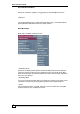
About This User’s Guide About This User's Guide Intended Audience This manual is intended for people who want to configure the FSG1100HN using the Web Configurator. You should have at least a basic knowledge of TCP/IP networking concepts and topology. Tips for Reading User’s Guides On-Screen When reading a ZyXEL User’s Guide On-Screen, keep the following in mind: • If you don’t already have the latest version of Adobe Reader, you can download it from http://www.adobe.com.
About This User’s Guide Documentation Feedback Send your comments, questions or suggestions to: techwriters@zyxel.com.tw. Thank you! The Technical Writing Team, ZyXEL Communications Corp., 6 Innovation Road II, Science-Based Industrial Park, Hsinchu, 30099, Taiwan. Need More Help? More help is available at www.zyxel.com. • Download Library Search for the latest product updates and documentation from this link.
About This User’s Guide Customer Support Should problems arise that cannot be solved by the methods listed above, you should contact your vendor. If you cannot contact your vendor, then contact a ZyXEL office for the region in which you bought the device. See http://www.zyxel.com/web/contact_us.php for contact information. Please have the following information ready when you contact an office. • Product model and serial number. • Warranty Information. • Date that you received your device.
Document Conventions Document Conventions Warnings and Notes These are how warnings and notes are shown in this User’s Guide. Warnings tell you about things that could harm you or your device. Note: Notes tell you other important information (for example, other things you may need to configure or helpful tips) or recommendations. Syntax Conventions • The FSG1100HN may be referred to as the “FSG1100HN”, the “device”, the “product” or the “system” in this User’s Guide.
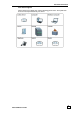
Document Conventions Icons Used in Figures Figures in this User’s Guide may use the following generic icons. The ZyXEL icon is not an exact representation of your device.
Safety Warnings Safety Warnings • Do NOT use this product near water, for example, in a wet basement or near a swimming pool. • Do NOT expose your device to dampness, dust or corrosive liquids. • Do NOT store things on the device. • Do NOT install, use, or service this device during a thunderstorm. There is a remote risk of electric shock from lightning. • Connect ONLY suitable accessories to the device. • Do NOT open the device or unit.
SAFETY WARNINGS FSG1100HN User’s Guide 9
Table of Contents Table of Contents FSG1100HN ............................................................................................................... 1 About This User's Guide........................................................................................................................................ 3 Safety Warnings ........................................................................................................................................................
Table of Contents 6.4.1 6.4.2 Active DHCP Client Table ................................................................................................................ 59 Static DHCP .......................................................................................................................................... 60 6.5 VLAN Screen .............................................................................................................................................. 61 7 NAT ................
PART I Introduction Getting to Know Your FSG-100HN (15) The WPS Button (19) Introducing the Web Configurator (21) Setting the Device Mode (24) FSG1100HN User’s Guide 13
Chapter 2 The WPS Button 1 Getting to Know Your FSG1100HN 1.1 Overview This chapter introduces the main features and applications of the FSG1100HN. The FSG1100HN extends the range of your existing wired network without additional wiring, providing easy network access to mobile users. You can set up a wireless network with other IEEE 802.11b/g/n compatible devices. A range of services such as a firewall and content filtering are also available for secure Internet computing. 1.
Chapter 2 The WPS Button 1.3 Ways to Manage the FSG1100HN Use any of the following methods to manage the FSG1100HN. • WPS (Wi-Fi Protected Setup). You can use the WPS button or the WPS section of the Web Configurator to set up a wireless network with your ZyXEL Device. • Web Configurator. This is recommended for everyday management of the FSG1100HN using a (supported) web browser. 1.
Chapter 2 The WPS Button The following table describes the LEDs and the WPS button. Front Panel LEDs and WPS Button LED Power COLOR Green STATUS On WAN Red Green Off On On Blinking Off WLAN/WPS Green On Blinking Internet Orange Off Blinking Green On Blinking FSG1100HN User’s Guide DESCRIPTION The FSG1100HN is receiving power and functioning properly The FSG1100HN is not receiving power. A system error has occurred. The FSG1100HN has a successful 10/100Mbps WAN connection.
Chapter 2 The WPS Button Off LAN 1-4 WPS Button 18 The FSG1100HN’s power is off, it is in bridged mode, or a connection not present. Red On The FSG1100HN’s attempt to achieve an IP connection failed (no DHCP response, no PPPoE response, PPPoE authentication failed, no IP address from IPCP, etc.). Green On The FSG1100HN has a successful 10/100Mbps Ethernet connection. Blinking The FSG1100HN is sending/receiving data through the LAN, flashing at 4 HZ with a 50% duty cycle.
Chapter 2 The WPS Button 2 The WPS Button 2.1 Overview Your FSG1100N supports WiFi Protected Setup (WPS), which is an easy way to set up a secure wireless network. WPS is an industry standard specification, defined by the WiFi Alliance. WPS allows you to quickly set up a wireless network with strong security, without having to configure security settings manually. Each WPS connection works between two devices. Both devices must support WPS (check each device’s documentation to make sure).
Chapter 4 Wireless LAN 3 Introducing the Web Configurator 3.1 Overview This chapter describes how to access the FSG1100HN Web Configurator and provides an overview of its screens. The Web Configurator is an HTML-based management interface that allows easy setup and management of the FSG1100HN via Internet browser. Use Internet Explorer 6.0 and later or Netscape Navigator 7.0 and later versions or Safari 2.0 or later versions. The recommended screen resolution is 1024 by 768 pixels.
Chapter 4 Wireless LAN 4. Type "1234" (default) as the password and click Login. In some versions, the default password appears automatically - if this is the case, click Login. 5. You should see a screen asking you to change your password (highly recommended) as shown next. Type a new password (and retype it to confirm) and click Apply or click Ignore.
Chapter 4 Wireless LAN 3.4 Navigating the Web Configurator The following summarizes how to navigate the Web Configurator from the Status screen. Status Screen Click this icon at anytime to exit the Web Configurator. Web Configurator Status Screen LABEL DESCRIPTION Device Information System Name This is the System Name you enter in the Maintenance > System Settings > General screen. It is for identification purposes. Firmware Version This is the firmware version.
Chapter 4 Wireless LAN LAN Information IP Address This is the LAN port’s IP address. IP Subnet Mask This is the LAN port’s subnet mask. DHCP This is the LAN port’s DHCP role, Enable or Disable. System Status Interface These are the devices three types of interfaces. Status This is the current status of each interface type. CPU Usage This displays what percentage of the FSG1100HN’s processing ability is currently used.
Chapter 4 Wireless LAN The following table describes the multiple AP labels in this screen Status > Multiple AP 3.4.2 LABEL DESCRIPTION SSID This displays the Service Set Identity (SSID) associated with the AP. Band This displays the operating frequency for the AP. The options are: 2.4 GHz (B+G+N) for networks using a mix of 802.11b, 802.11g, and 802.11n wireless clients, 2.4 GHz (G+N) for networks using a mix of 802.11g and 802.11n wireless clients, 2.4 GHz (B+G) for networks using a mix of 802.
Chapter 4 Wireless LAN System Information > Active Session 3.5 LABEL DESCRIPTION Index The index number of the active session table entry. Internal The internal IP address of the of the active session table entry. Protocol The protocol of the active session table entry. External The external IP address of the of the active session table entry. NAT (Port) The NAT port number of the active session entry. Time Out (sec) The time, in seconds, until the active session entry times out.
PART II Network Wireless LAN (30) WAN (48) LAN (56) Network Address Translation (NAT) (63) 28 FSG1100HN User’s Guide
FSG1100HN User’s Guide 29
Chapter 4 Wireless LAN 4 Wireless LAN 4.1 Overview This chapter discusses how to configure the wireless network settings in your FSG1100HN. See the appendices for more detailed information about wireless networks. The following figure provides an example of a wireless network. Example of a Wireless Network The wireless network is the part in the blue circle. In this wireless network, devices A and B are called wireless clients.
Chapter 4 Wireless LAN 4.2 What You Can Do • Use the Basic screen (32) to configure the basic wireless settings, including to enable the Wireless LAN, select the band, display the currently configured multiple APs, enter the SSID, select the channel width, set the control sideband, select a channel number, enable broadcast SSID, set the data rate, and display active clients.
Chapter 4 Wireless LAN 4.4 Wireless Basic Settings Screen The Wireless Basic Settings window allows users to configure the Wireless LAN Interface. Click Wireless > Basic Settings to open the Wireless Basic Settings screen. Wireless > Basic Settings The following table describes the basic wireless labels in this screen. Wireless > Basic Settings LABEL DESCRIPTION Wireless Basic Settings 32 Wireless LAN Interface Enable or disable the wireless LAN interface on the FSG1100HN.
Chapter 4 Wireless LAN FSG1100HN to adjust the channel bandwidth automatically. 4.4.1 Channel Number Select the channel number for the wireless network between 1 and 11 or select Auto to automatically scan for an active channel on the network. Broadcast SSID Enable or disable the broadcasting of the FSG1100HN’s SSID. If this is disabled, the SSID in the outgoing beacon frame will be hidden. This prevents a station from obtaining the SSID through scanning using a site survey tool.
Chapter 4 Wireless LAN built-in to the FSG1100HN must have the same SSID. 4.4.2 Data Rate Select the data transmission rate. For best performance, it is strongly suggested to choose the default, Auto. Broadcast SSID Enable or disable the broadcasting of the FSG1100HN’s SSID. If this is disabled, the SSID in the outgoing beacon frame will be hidden. This prevents a station from obtaining the SSID through scanning using a site survey tool.
Chapter 4 Wireless LAN 4.5 Wireless Advanced Settings Screen The Wireless Advanced Settings window allows users to configure the Wireless LAN Interface. Click Wireless > Advanced Settings to open the Wireless Advanced Settings screen.
Chapter 4 Wireless LAN Short GI Enable or disable Short Guard Interval (GI). Enabling this feature reduces the guard interval time thereby increasing data capacity. The drawback is that it can be less reliable and may create higher data loss. Block IntraBSS Traffic Enable or disable Intra-BSS Traffic. A Basic Service Set (BSS) exists when all communications between wireless clients or between a wireless client and a wired network client go through one access point.
Chapter 4 Wireless LAN 4.6 Wireless Security Screen The Wireless Security Setup window allows users to configure WEP, WPA, WPA2, and WPA-Mixed encryption. Click Wireless > Security to open the Wireless Security screen. Wireless > Security The following table describes the wireless security labels in this screen Wireless > Security LABEL DESCRIPTION Wireless Security Setup 4.6.1 Select SSID Select the desired Service Set Identity (SSID).
Chapter 4 Wireless LAN Wireless > Security > WEP The following table describes the wireless security for WEP labels in this screen Wireless > Security > WEP LABEL DESCRIPTION Wireless Security Setup Select SSID Select the desired Service Set Identity (SSID). Encryption Choose the encryption security type, WEP. The other encryption security options are: WPA, WPA2, WPA-Mixed, and Disable. The default is Disable. Authentication Select Open System, Shared Key, or Auto authentication.
Chapter 4 Wireless LAN 4.6.2 WPA Wi-Fi Protected Access (WPA) is an encryption security option designed to improve upon the features of WEP. It employs Temporal Key Integrity Protocol (TKIP) to scramble the keys using a hash algorithm and, by adding an integrity-checking feature, ensures that the keys have not been tampered with. WPA-PSK/WPA2-PSK uses a passphrase or key to authenticate wireless connections. The key is an alphanumeric password between 8 and 63 characters long.
Chapter 4 Wireless LAN LABEL DESCRIPTION Wireless Security Setup Select SSID Select the desired Service Set Identity (SSID). Encryption Choose the encryption security type, WPA. The other encryption security options are: WEP, WPA2, WPA-Mixed, and Disable. The default is Disable. Authentication Mode Select Enterprise (RADIUS) or Personal (Pre-Shared Key) authentication. Personal (Pre-Shared Key) is the default. WPA Suite Tick the Cipher Suite type, TKIP or AES.
Chapter 4 Wireless LAN 4.6.3 WPA2 Click Wireless > Security > WPA2 to open the Wireless Security WPA2 screens. Wireless > Security > WPA2 Wireless Security Setup window for WPA2 (Personal (Pre-Shared Key)) Wireless Security Setup window for WPA2 (Enterprise (RADIUS)) The following table describes the wireless security for WPA2 labels in these screens.
Chapter 4 Wireless LAN LABEL DESCRIPTION Wireless Security Setup 4.6.4 Select SSID Select the desired Service Set Identity (SSID). Encryption Choose encryption security type WPA2. The other encryption security options are: WEP, WPA, WPA-Mixed, and Disable. The default is Disable. Authentication Mode Select Enterprise (RADIUS) or Personal (Pre-Shared Key) authentication. Personal (Pre-Shared Key) is the default. WPA2 Cipher Suite Tick the Cipher Suite type, TKIP or AES.
Chapter 4 Wireless LAN Wireless Security Setup window for WPA-Mixed (Personal (Enterprise (RADIUS)) The following table describes the wireless security for WPA-Mixed labels in these screens. Wireless > Security > WPA-Mixed LABEL DESCRIPTION Wireless Security Setup Select SSID Select the desired Service Set Identity (SSID). Encryption Choose the encryption security type, WPA-Mixed. The other encryption security options are: WEP, WPA, WPA2, and Disable. The default is Disable.
Chapter 4 Wireless LAN 4.7 Wireless Access Control Screen The Wireless Access Control window allows users to configure wireless access control by creating a white list and a black list. This allows administrators to block users or only allow approved users to make a connection. Click Wireless > Access Control to open the Wireless Access Control screen. Wireless > Access Control The following table describes the wireless access control labels in this screen.
Chapter 4 Wireless LAN Click Wireless > WPS to open the Wi-Fi Protected Setup screen. Wireless > WPS The following table describes the WPS labels in this screen. Wireless > WPS LABEL DESCRIPTION WPS Settings Active Enable or Disable the WPS feature. Click Apply to commit the setting. Click Refresh to display current settings of the window.
Chapter 4 Wireless LAN PBC 46 Push Button Configuration (PBC) allows users to click the Configure via PBC button to set up WPS. Once the button is clicked on this window, users have 2 minutes to press a similar virtual or actual button on the new wireless client device.
Chapter 4 Wireless LAN FSG1100HN User’s Guide 47
Chapter 5 WAN 5 WAN 5.1 Overview This chapter discusses the FSG1100HN’s WAN screens. Use these screens to configure your FSG1100HN for Internet access. A WAN (Wide Area Network) connection is an outside connection to another network or the Internet. It connects your private networks (such as a LAN (Local Area Network) and other networks, so that a computer in one location can communicate with computers in other locations. LAN and WAN 5.
Chapter 5 WAN 5.3 WAN for DHCP Client Screen Dynamic Host Configuration Protocol (DHCP), based on RFC 2131 and RFC 2132, allows individual clients to obtain TCP/IP configuration at start-up from a server. Users can configure the FSG1100HN’s LAN as a DHCP server or disable it. When configured as a server, the FSG1100HN provides the TCP/IP configuration for the clients. If DHCP service is disabled, another DHCP server must be available on that network, or the computer will need to be manually configured.
Chapter 5 WAN the device discovered through standard IGMP interfaces. 50 Enable Ping Access on WAN Enable the Ping access on WAN feature. This allows Ping to use the WAN to send ICMP echo request packets to the target host and listen for ICMP echo response replies. Enable Web Server Access on WAN Enable the Web server access on WAN feature. This allows Web server access via the WAN. Enable IPSec Pass Through on VPN Connection Enable the IPSec Pass Through on VPN connection feature.
Chapter 5 WAN 5.4 WAN for Static IP Screen Select Static IP if the WAN port IP information is provided by the ISP. Users will need to enter the IP address, subnet mask, gateway address, and DNS(es) provided by the ISP. Click Networking > WAN > Static IP to open the WAN screen for Static IP. Networking > WAN > Static IP The following table describes the WAN static IP labels in this screen. Networking > WAN > Static IP LABEL DESCRIPTION WAN Settings WAN Access Type Choose Static IP.
Chapter 5 WAN Enable IGMP Proxy 52 uses TCP/IP for simple peer-to-peer network connectivity between devices. A UPnP device can dynamically join a network, obtain an IP address, convey its capabilities and learn about other devices on the network. In turn, a device can leave a network smoothly and automatically when it is no longer in use. Enable the IGMP proxy feature. IGMP proxy enables the device to issue IGMP host messages on behalf of hosts that the device discovered through standard IGMP interfaces.
Chapter 5 WAN 5.5 WAN for PPPoE Screen Point-to-Point Protocol over Ethernet (PPPoE) emulates a dial-up connection. It allows an ISP to use their existing network configuration with newer broadband technologies such as ADSL. The PPPoE driver on the FSG1100HN is transparent to the computers on the LAN, which see only Ethernet and are not aware of PPPoE thus saving users the need to manage PPPoE clients on individual computers. Click Networking > WAN > PPPoE to open the WAN screen for PPPoE.
Chapter 5 WAN Attain DNS Automatically Click to attain DNS automatically. Otherwise, enter DNS manually using the field below. Set DNS Manually Enter the DNS server IP address(es) assigned by the ISP. DNS1-DNS3 Enter the DNS server IP address(es) assigned by the ISP. Clone MAC Address Enable MAC address cloning. Enable UPnP Enable the Universal Plug and Play (UPnP) feature.
Chapter 5 WAN FSG1100HN User’s Guide 55
Chapter 6 LAN 6 LAN 6.1 Overview This chapter describes how to configure LAN settings. A Local Area Network (LAN) is a shared communication system to which many computers are attached. A LAN is a computer network limited to the immediate area, usually the same building or floor of a building. The LAN screens can help you configure a LAN DHCP server, manage IP addresses, and partition your physical network into logical networks. LAN Setup 6.
Chapter 6 LAN 6.3 What You Need To Know The actual physical connection determines whether the FSG1100HN ports are LAN or WAN ports. There are two separate IP networks, one inside the LAN network and the other outside the WAN network as shown next. LAN and WAN IP Addresses The LAN parameters of the FSG1100HN are preset in the factory with the following values: • IP address of 192.168.1.254 with subnet mask of 255.255.255.0 (24 bits) • DHCP server enabled with 32 client IP addresses starting from 192.168.
Chapter 6 LAN 6.4 LAN General Screen The LAN window General tab allows users to configure and display LAN settings. A Local Area Network (LAN) is a shared communication system to which many computers are attached. A LAN is a computer network limited to the immediate area, usually the same building or floor of a building. The LAN windows can help users configure a LAN DHCP server, manage IP addresses, and partition the physical network into logical networks.
Chapter 6 LAN Enable this setting and click Set Static DHCP. Select an Index between 1 and 20, enter an IP Address, a MAC Address, and an optional identifying Comment in the Static DHCP window displayed on the next page. Domain Name Enter the domain name. If this is left blank, the ISP may assign a domain name via DHCP. IP Alias 6.4.1 IP Alias Choose Enable to configure the LAN network for the FSG1100HN. IP Address Enter the IP address of the FSG1100HN in dotted decimal notation.
Chapter 6 LAN 6.4.2 Static DHCP The Static DHCP window allows users to set up static DHCP on the FSG1100HN. Select an index between 1 and 20, enter an IP address, a MAC Address, and an optional identifying comment. A Static DHCP List at the bottom of the window displays the current static DHCP entries. Click Networking > LAN > Set Static DHCP to open the Static DHCP screen. Networking > LAN > Set Static DHCP The following table describes the static DHCP labels in this screen.
Chapter 6 LAN 6.5 VLAN Screen The VLAN screen allows users to configure VLAN settings. Click Networking > VLAN to open the VLAN screen. Networking > VLAN The following table describes the VLAN labels in this screen. Networking > VLAN LABEL DESCRIPTION VLAN Settings VLAN Enable or disable VLANs. Index An index number for the VLAN entry (row) Enable Tick to enable the VLAN entry. Ethernet/Wireless This column displays the VLAN’s interface.
Chapter 6 LAN 62 FSG1100HN User’s Guide
Chapter 7 NAT 7 NAT 7.1 Overview This chapter discusses how to configure NAT on the FSG1100HN. NAT (Network Address Translation – NAT, RFC 1631) is the translation of the IP address of a host in a packet. For example, the source address of an outgoing packet, used within one network is changed to a different IP address known within another network. Each packet has two addresses – a source address and a destination address.
Chapter 7 NAT 7.3 NAT General Screen The NAT window General tab allows users to configure NAT settings. NAT (Network Address Translation – NAT, RFC 1631) is the translation of the IP address of a host in a packet. For example, the source address of an outgoing packet, used within one network is changed to a different IP address known within another network. Each packet has two addresses – a source address and a destination address.
Chapter 7 NAT Apply Click Apply to save your changes back to the FSG1100HN. Refresh Click Refresh to begin configuring this screen afresh.
Chapter 7 NAT 7.4 NAT DMZ Screen Demilitarized Zone (DMZ) allows one IP address to be exposed to the Internet. This is useful for special-purpose services such as Internet gaming or video conferencing. However, as any user on the Internet can access in/out data from the DMZ host, care should be taken when using this feature to minimize security issues. Click Networking > NAT > DMZ to open the NAT DMZ screen. Networking > NAT > DMZ The following table describes the NAT DMZ labels in this screen.
Chapter 7 NAT 7.5 NAT Port Forwarding Screen Port forwarding allows users to define the local servers to which incoming services will be forwarded by creating a firewall between the internal network and the Internet. A tunnel is created so that computers on the Internet can communicate to computers on a user’s LAN through a single port. This is useful for running Web servers, game servers, FTP servers, and video conferencing and is more secure than DMZ.
Chapter 7 NAT 68 FSG1100HN User’s Guide
PART III Security Firewall (71) FSG1100HN User’s Guide 69
FSG1100HN User’s Guide
Chapter 8 Firewall 8 Firewall Overview Use these screens to enable and configure the firewall that protects your FSG1100HN and your LAN from unwanted or malicious traffic. Enable the firewall to protect your LAN computers from attacks by hackers on the Internet and control access between the LAN and WAN. By default the firewall: • allows traffic that originates from your LAN computers to go to all of the networks. • blocks traffic that originates on the other networks from going to the LAN.
Chapter 8 Firewall 8.1 What You Can Do • Use the Firewall Filter screen (73) to enable or disable the FSG1100HN’s firewall. • Use the Firewall Filter Add screen (74) to add a filter to the FSG1100HN firewall. • Use the Firewall Denial of Service screen (75) to enable and configure Denial of Service Prevention. • Use the Firewall Content Filter screen (75) to restrict Web features, add keywords for blocking, and designate a trusted computer. 8.
Chapter 8 Firewall 8.3 Firewall Filter Screen The Filter window allows users to view existing filters on the FSG1100HN. To set up a new filter, click the Add button. Click Firewall > Filter to open the Filter screen. Firewall > Filter The following table describes the filter labels in this screen. Firewall > Filter LABEL DESCRIPTION Rule Setup Index Displays filter index number. Active Displays current filter status. Protocol Displays the current filter protocol setting.
Chapter 8 Firewall 8.4 Firewall Filter Add Screen The Rule Configuration screen allows users to set up filtering rules. Click Firewall > Filter > Add to open the Rule Configuration screen. Firewall > Filter > Add The following table describes the filter labels in this screen. Firewall > Filter > Add LABEL DESCRIPTION Rule Configuration Active Enable or disable filtering. Protocol Select which protocol to use to filter incoming packets: Both, TCP, UDP, or Any.
Chapter 8 Firewall Destination Enter the range of ports to be filtered between 1 and 65535. -- Port Range Apply Click Apply to save your changes back to the FSG1100HN. Refresh Click Refresh to begin configuring this screen afresh. Back 8.5 Click Back to return to the main Filter screen. Firewall Denial of Service Screen The Denial of Service screen allows users to prevent various types of Denial of Service attacks. Click Firewall > Denial of Service to open the Denial of Service screen.
Chapter 8 Firewall 76 Whole System Flood: SYN Tick to enable whole system flooding for SYN DoS prevention. Whole System Flood: FIN Tick to enable whole system flooding for FIN DoS prevention. Whole System Flood: UDP Tick to enable whole system flooding for UDP DoS prevention. Whole System Flood: ICMP Tick to enable whole system flooding for ICMP DoS prevention. Per-Source IP Flood: SYN Tick to enable per-source IP flooding for SYN DoS prevention.
Chapter 8 Firewall 8.6 Firewall Content Filter Screen The Content Filter screen allows users to restrict Web features, add keywords for blocking, and designate a trusted computer. A content filtering profile conveniently stores your custom settings for the following features. Restrict Web Features The FSG1100HN can disable Web proxies and block Web features such as ActiveX controls, Java applets, and cookies.
Chapter 8 Firewall Keyword Add Type a keyword in this field. You may use any character (up to 64 characters). Wildcards are not allowed. You can also enter a numerical IP address. Click Add after you have typed a keyword. Repeat this procedure to add other keywords. Up to 64 keywords are allowed. Refresh When you try to access a Web page containing a keyword, you will get a message telling you that the content filter is blocking this request. Click Refresh to begin configuring this screen afresh.
Chapter 8 Firewall FSG1100HN User’s Guide 79
PART IV Management Bandwidth Maintenance (82) TR-069 (85) Auto Provision (88) 80 FSG1100HN User’s Guide
FSG1100HN User’s Guide 81
Chapter 9 Media Bandwidth Management 9 Media Bandwidth Management 9.1 Media Bandwidth Management Screen The Media Bandwidth Management screen allows users to configure bandwidth rules for pre-defined services or applications. Click Networking > MBM to open the Media Bandwidth Management screen. Networking > MBM The following table describes the media bandwidth management labels in this screen.
Chapter 9 Media Bandwidth Management Protocol Select the protocol: TCP, UDP, TCP/UDP, ICMP, or Any. Local IP Address Enter the IP address of the computer to which the bandwidth rule does not apply. This is the range of ports for which the bandwidth rule applies. Port Mode Choose Guaranteed minimum Restricted maximum bandwidth. Uplink Bandwidth Enter the uplink bandwidth in Kbps. Downlink Bandwidth Enter the downlink bandwidth in Kbps.
Chapter 9 Media Bandwidth Management 84 FSG1100HN User’s Guide
Chapter 10 TR-069 10 TR-069 10.1 TR-069 General Screen The TR-069 General tab allows users to configure a TR-069 Auto-Configuration Server (ACS). Click Management > TR-069 > General to open the TR-069 General screen. Management > TR-069 > General The following table describes the TR-069 general labels in this screen. Management > TR-069 > General LABEL DESCRIPTION ACS ACS URL Enter the URL of the ACS. User Name Enter the user name for the ACS. Password Enter the password for the ACS.
Chapter 10 TR-069 Refresh 86 Click Refresh to begin configuring this screen afresh.
Chapter 10 TR-069 FSG1100HN User’s Guide 87
Chapter 11 Auto Provision 11 Auto Provision 11.1 Auto Provision Screen The Auto Provision screen allows automatic updating of configurable settings for configuration files and image files via TFTP, FTP server, or HTTP server. Click Management > Auto Provision to open the Auto Provision screen. Management > Auto Provision The following table describes the auto provision labels in this screen.
Chapter 11 Auto Provision Refresh Click Refresh to begin configuring this screen afresh.
Chapter 11 Auto Provision 90 FSG1100HN User’s Guide
PART V Maintenance and Troubleshooting System Settings (93) Log (98) Tools (100) FSG1100HN User’s Guide 91
FSG1100HN User’s Guide
Chapter 12 System Settings 12 System Settings 12.1 System Settings General Screen The System Settings screen’s General tab allows users to enter a name to identify the FSG1100HN on the network, configure the administrator inactivity timer, and set the system password. Click Maintenance > System Settings > General to open the System Settings General screen. Maintenance > System Settings > General The following table describes the system settings general labels in this screen.
Chapter 12 System Settings Password New Password access the system in this field. The default password of the FSG1100HN is “1234”. Type your new system password (up to 30 characters). Note that as you type a password, the screen displays an asterisk (*) for each character you type. Retype to Confirm Type the new password again in this field. Apply Click Apply to save your changes back to the FSG1100HN. Refresh Click Refresh to begin configuring this screen afresh. 12.
Chapter 12 System Settings 12.3 System Settings Time Screen The System Settings’ Time tab allows time, date, and time zone configuration, including use of an NTP Server and setting up DST on the FSG1100HN. Click Maintenance > System Settings > Time to open the System Settings Time screen. Maintenance > System Settings > Dynamic DNS The following table describes the system settings time labels in this screen.
Chapter 12 System Settings Time Zone Setup Time Zone Choose the time zone of your location. This will set the time difference between your time zone and Greenwich Mean Time (GMT). Daylight Savings Daylight saving is a period from late spring to early fall when many countries set their clocks ahead of normal local time by one hour to give more daytime light in the evening. Select this option if you use Daylight Saving Time.
Chapter 12 System Settings FSG1100HN User’s Guide 97
Chapter 13 Log 13 Log 13.1 Log Screen The Log screen allows users to configure and display system logs. Click Maintenance > Log to open the Log screen. Maintenance > Log The following table describes the system settings log labels in this screen. Maintenance > Log 98 LABEL DESCRIPTION Enable Log Tick to enable the system log. System All Tick to enable all types of system logs. Wireless Tick to enable the wireless system log. Enable Remote Log Tick to enable a remote system log.
Chapter 13 Log FSG1100HN User’s Guide 99
Chapter 14 Tools 14 Tools 14.1 Tools Firmware Screen This screen allows users to upgrade firmware. Click Maintenance > Tools > Firmware to open the Firmware screen. Maintenance > Tools > Firmware Tools window – Firmware tab The following table describes the tools firmware labels in this screen. Maintenance > Tools > Firmware LABEL DESCRIPTION Firmware Upgrade Choose File Click to choose the file name and file path of the configuration file to be restored.
Chapter 14 Tools Maintenance > Tools > Configuration The following table describes the tools configuration labels in this screen. Maintenance > Tools > Configuration LABEL DESCRIPTION Backup Configuration - Allows you to back up (save) the FSG1100HN’s current configuration to a file on your computer. Once your FSG1100HN is configured and functioning properly, it is highly recommended that you back up your configuration file before making configuration changes.
Chapter 14 Tools Maintenance > Tools > Restart Tools window – Restart tab Click Restart to reboot the FSG1100HN. The following table describes the tools restart label in this screen. Maintenance > Tools > Restart LABEL DESCRIPTION Restart Restart 102 Click to have the FSG1100HN reboot. This does not effect the FSG1100HN’s configuration.
Chapter 14 Tools FSG1100HN User’s Guide 103
PART VI Appendices Pop-up Windows, JavaScripts and Java Permissions (106) IP Addresses and Subnetting (114) Setting up Your Computer’s IP Address (124) Wireless LANs (142) Services (154) Legal Information (158) 104 FSG1100HN User’s Guide
FSG1100HN User’s Guide 105
Appendix A Pop-up Windows, JavaScripts, and Java Permissions A Pop-up Windows, JavaScripts and Java Permissions In order to use the Web Configurator you need to allow: • Web browser pop-up windows from your device. • JavaScripts (enabled by default). • Java permissions (enabled by default). Note: Internet Explorer 6 screens are used here. Screens for other Internet Explorer versions may vary. Internet Explorer Pop-up Blockers You may have to disable pop-up blocking to log into your device.
Appendix A Pop-up Windows, JavaScripts, and Java Permissions 2 In Internet Explorer, select Tools, Internet Options, Privacy. 3 Clear the Block pop-ups check box in the Pop-up Blocker section of the screen. This disables any web pop-up blockers you may have enabled. Internet Options: Privacy 4 Click Apply to save this setting. Enable pop-up Blockers with Exceptions Alternatively, if you only want to allow pop-up windows from your device, see the following steps.
Appendix A Pop-up Windows, JavaScripts, and Java Permissions 2 Select Settings…to open the Pop-up Blocker Settings screen. Internet Options: Privacy 3 Type the IP address of your device (the web page that you do not want to have blocked) with the prefix “http://”. For example, http://192.168.167.1.
Appendix A Pop-up Windows, JavaScripts, and Java Permissions 4 Click Add to move the IP address to the list of Allowed sites. Pop-up Blocker Settings 5 Click Close to return to the Privacy screen. 6 Click Apply to save this setting. JavaScripts If pages of the Web Configurator do not display properly in Internet Explorer, check that JavaScripts are allowed.
Appendix A Pop-up Windows, JavaScripts, and Java Permissions 1 In Internet Explorer, click Tools, Internet Options and then the Security tab. Internet Options: Security 2 Click the Custom Level... button. 3 Scroll down to Scripting. 4 Under Active scripting make sure that Enable is selected (the default). 5 Under Scripting of Java applets make sure that Enable is selected (the default).
Appendix A Pop-up Windows, JavaScripts, and Java Permissions 6 Click OK to close the window. Security Settings - Java Scripting Java Permissions 1 From Internet Explorer, click Tools, Internet Options and then the Security tab. 2 Click the Custom Level... button. 3 Scroll down to Microsoft VM. 4 Under Java permissions make sure that a safety level is selected.
Appendix A Pop-up Windows, JavaScripts, and Java Permissions 5 Click OK to close the window. Security Settings – Java JAVA (Sun) 1 From Internet Explorer, click Tools, Internet Options and then the Advanced tab. 2 Make sure that Use Java 2 for
Appendix A Pop-up Windows, JavaScripts, and Java Permissions 3 Click OK to close the window.
Appendix B IP Addresses and Subnetting B IP Addresses and Subnetting This appendix introduces IP addresses and subnet masks. IP addresses identify individual devices on a network. Every networking device (including computers, servers, routers, printers, etc.) needs an IP address to communicate across the network. These networking devices are also known as hosts. Subnet masks determine the maximum number of possible hosts on a network.
Appendix B IP Addresses and Subnetting The following figure shows an example IP address in which the first three octets (192.168.1) are the network number, and the fourth octet (16) is the host ID. Network Number and Host ID How much of the IP address is the network number and how much is the host ID varies according to the subnet mask. Subnet Masks A subnet mask is used to determine which bits are part of the network number, and which bits are part of the host ID (using a logical AND operation).
Appendix B IP Addresses and Subnetting Subnet Mask - Identifying Network Number Network Number Host ID 1ST OCTET: (192) 11000000 2ND OCTET: (168) 10101000 3RD OCTET: (1) 00000001 4TH OCTET: (2) 00000010 By convention, subnet masks always consist of a continuous sequence of ones beginning from the leftmost bit of the mask, followed by a continuous sequence of zeros, for a total number of 32 bits. Subnet masks can be referred to by the size of the network number part (the bits with a “1” value).
Appendix B IP Addresses and Subnetting As these two IP addresses cannot be used for individual hosts, calculate the maximum number of possible hosts in a network as follows: Maximum Host Numbers SUBNET MASK HOST ID SIZE 8 bits 16 bits 24 bits 29 bits 24 bits 16 bits 8 bits 3 bits 255.0.0.0 255.255.0.0 255.255.255.0 255.255.255.
Appendix B IP Addresses and Subnetting Subnetting You can use subnetting to divide one network into multiple sub-networks. In the following example a network administrator creates two sub-networks to isolate a group of servers from the rest of the company network for security reasons. In this example, the company network address is 192.168.1.0. The first three octets of the address (192.168.
Appendix B IP Addresses and Subnetting The following figure shows the company network after subnetting. There are now two sub-networks, A and B. Subnetting Example: After Subnetting In a 25-bit subnet the host ID has 7 bits, so each sub-network has a maximum of 7 2 – 2 or 126 possible hosts (a host ID of all zeroes is the subnet’s address itself, all ones is the subnet’s broadcast address). 192.168.1.0 with mask 255.255.255.128 is subnet A itself, and 192.168.1.127 with mask 255.255.255.
Appendix B IP Addresses and Subnetting Each subnet contains 6 host ID bits, giving 26 - 2 or 62 hosts for each subnet (a host ID of all zeroes is the subnet itself, all ones is the subnet’s broadcast address). Subnet 1 IP/SUBNET MASK NETWORK NUMBER IP Address (Decimal) IP Address (Binary) Subnet Mask (Binary) Subnet Address: 192.168.1.0 Broadcast Address: 192.168.1.63 192.168.1. 11000000.10101000.00000001. 11111111.11111111.11111111. Lowest Host ID: 192.168.1.
Appendix B IP Addresses and Subnetting Example: Eight Subnets Similarly, use a 27-bit mask to create eight subnets (000, 001, 010, 011, 100, 101, 110 and 111). The following table shows IP address last octet values for each subnet.
Appendix B IP Addresses and Subnetting The following table is a summary for subnet planning on a network with a 16-bit network number. 16-bit Network Number Subnet Planning NO. “BORROWED” HOST BITS 1 2 3 4 5 6 7 8 9 10 11 12 13 14 15 SUBNET MASK 255.255.255.0 (/17) 255.255.255.0 (/18) 255.255.255.0 (/19) 255.255.255.0 (/20) 255.255.255.0 (/21) 255.255.255.0 (/22) 255.255.255.0 (/23) 255.255.255.0 (/24) 255.255.255.128 (/25) 255.255.255.192 (/26) 255.255.255.224 (/27) 255.255.255.240 (/28) 255.255.255.
Appendix B IP Addresses and Subnetting address that you entered. You don't need to change the subnet mask computed by the FSG1100HN unless you are instructed to do otherwise. Private IP Addresses Every machine on the Internet must have a unique address. If your networks are isolated from the Internet (running only between two branch offices, for example) you can assign any IP addresses to the hosts without problems.
Appendix C Setting up Your Computer’s IP Address C Setting up Your Computer’s IP Address All computers must have a 10M or 100M Ethernet adapter card and TCP/IP installed. Windows 95/98/Me/NT/2000/XP, Macintosh OS 7 and later operating systems and all versions of UNIX/LINUX include the software components you need to install and use TCP/IP on your computer. Windows 3.1 requires the purchase of a third party TCP/IP application package.
Appendix C Setting up Your Computer’s IP Address Windows 95/98/Me Click Start, Settings, Control Panel and double-click the Network icon to open the Network window. Windows 95/98/Me: Network: Configuration Installing Components The Network window Configuration tab displays a list of installed components. You need a network adapter, the TCP/IP protocol and Client for Microsoft Networks. If you need the adapter: 1 In the Network window, click Add. 2 Select Adapter and then click Add.
Appendix C Setting up Your Computer’s IP Address 3 Select Microsoft from the list of manufacturers. 4 Select TCP/IP from the list of network protocols and then click OK. If you need Client for Microsoft Networks: 1 Click Add. 2 Select Client and then click Add. 3 Select Microsoft from the list of manufacturers. 4 Select Client for Microsoft Networks from the list of network clients and then click OK. 5 Restart your computer so the changes you made take effect.
Appendix C Setting up Your Computer’s IP Address 3 Click the DNS Configuration tab. • If you do not know your DNS information, select Disable DNS. • If you know your DNS information, select Enable DNS and type the information in the fields below (you may not need to fill them all in). Windows 95/98/Me: TCP/IP Properties: DNS Configuration 4 Click the Gateway tab. • If you do not know your gateway’s IP address, remove previously installed gateways.
Appendix C Setting up Your Computer’s IP Address 3 Select your network adapter. You should see your computer's IP address, subnet mask and default gateway. Windows 2000/NT/XP The following example figures use the default Windows XP GUI theme. 1 Click start (Start in Windows 2000/NT), Settings, Control Panel.
Appendix C Setting up Your Computer’s IP Address 2 In the Control Panel, double-click Network Connections (Network and Dialup Connections in Windows 2000/NT). Windows XP: Control Panel 3 Right-click Local Area Connection and then click Properties.
Appendix C Setting up Your Computer’s IP Address 4 Select Internet Protocol (TCP/IP) (under the General tab in Win XP) and then click Properties. Windows XP: Local Area Connection Properties 5 The Internet Protocol TCP/IP Properties window opens (the General tab in Windows XP). • If you have a dynamic IP address click Obtain an IP address automatically. • If you have a static IP address click Use the following IP Address and fill in the IP address, Subnet mask, and Default gateway fields.
Appendix C Setting up Your Computer’s IP Address Windows XP: Internet Protocol (TCP/IP) Properties 6 If you do not know your gateway's IP address, remove any previously installed gateways in the IP Settings tab and click OK. Do one or more of the following if you want to configure additional IP addresses: • In the IP Settings tab, in IP addresses, click Add. • In TCP/IP Address, type an IP address in IP address and a subnet mask in Subnet mask, and then click Add.
Appendix C Setting up Your Computer’s IP Address • Click OK when finished. Windows XP: Advanced TCP/IP Properties 7 In the Internet Protocol TCP/IP Properties window (the General tab in Windows XP): • Click Obtain DNS server address automatically if you do not know your DNS server IP address(es). • If you know your DNS server IP address(es), click Use the following DNS server addresses, and type them in the Preferred DNS server and Alternate DNS server fields.
Appendix C Setting up Your Computer’s IP Address • If you have previously configured DNS servers, click Advanced and then the DNS tab to order them. Windows XP: Internet Protocol (TCP/IP) Properties 8 Click OK to close the Internet Protocol (TCP/IP) Properties window. 9 Click Close (OK in Windows 2000/NT) to close the Local Area Connection Properties window. 10 Close the Network Connections window (Network and Dial-up Connections in Windows 2000/NT).
Appendix C Setting up Your Computer’s IP Address Macintosh OS 8/9 1 Click the Apple menu, Control Panel and double-click TCP/IP to open the TCP/IP Control Panel.
Appendix C Setting up Your Computer’s IP Address 2 Select Ethernet built-in from the Connect via list. Macintosh OS 8/9: TCP/IP 3 For dynamically assigned settings, select Using DHCP Server from the Configure: list. 4 For statically assigned settings, do the following: • From the Configure box, select Manually. • Type your IP address in the IP Address box. • Type your subnet mask in the Subnet mask box. • Type the IP address of your Prestige in the Router address box. 5 Close the TCP/IP Control Panel.
Appendix C Setting up Your Computer’s IP Address Macintosh OS X 1 Click the Apple menu, and click System Preferences to open the System Preferences window. Macintosh OS X: Apple Menu 2 Click Network in the icon bar. • Select Automatic from the Location list. • Select Built-in Ethernet from the Show list. • Click the TCP/IP tab. 3 For dynamically assigned settings, select Using DHCP from the Configure list.
Appendix C Setting up Your Computer’s IP Address 4 For statically assigned settings, do the following: • From the Configure box, select Manually. • Type your IP address in the IP Address box. • Type your subnet mask in the Subnet mask box. • Type the IP address of your Prestige in the Router address box. 5 Click Apply Now and close the window. 6 Turn on your Prestige and restart your computer (if prompted). Verifying Settings Check your TCP/IP properties in the Network window.
Appendix C Setting up Your Computer’s IP Address 2 Double-click on the profile of the network card you wish to configure. The Ethernet Device General screen displays as shown. Red Hat 9.0: KDE: Ethernet Device: General • If you have a dynamic IP address click Automatically obtain IP address settings with and select dhcp from the drop down list. • If you have a static IP address click Statically set IP Addresses and fill in the Address, Subnet mask, and Default Gateway Address fields.
Appendix C Setting up Your Computer’s IP Address 5 Click the Devices tab. 6 Click the Activate button to apply the changes. The following screen displays. Click Yes to save the changes in all screens. Red Hat 9.0: KDE: Network Configuration: Activate 7 After the network card restart process is complete, make sure the Status is Active in the Network Configuration screen. Using Configuration Files Follow the steps below to edit the network configuration files and set your computer IP address.
Appendix C Setting up Your Computer’s IP Address • If you have a static IP address, enter static in the BOOTPROTO= field. Type IPADDR= followed by the IP address (in dotted decimal notation) and type NETMASK= followed by the subnet mask. The following example shows an example where the static IP address is 192.168.1.10 and the subnet mask is 255.255.255.0. Red Hat 9.0: Static IP Address Setting in ifconfig-eth0 DEVICE=eth0 ONBOOT=yes BOOTPROTO=static IPADDR=192.168.1.10 NETMASK=255.255.255.
Appendix C Setting up Your Computer’s IP Address Verifying Settings Enter ifconfig in a terminal screen to check your TCP/IP properties. Red Hat 9.0: Checking TCP/IP Properties [root@localhost]# ifconfig eth0 Link encap:Ethernet HWaddr 00:50:BA:72:5B:44 inet addr:172.23.19.129 Bcast:172.23.19.255 Mask:255.255.255.
Appendix D Wireless LANs D Wireless LANs Wireless LAN Topologies This section discusses ad-hoc and infrastructure wireless LAN topologies. Ad-hoc Wireless LAN Configuration The simplest WLAN configuration is an independent (Ad-hoc) WLAN that connects a set of computers with wireless stations (A, B, C). Any time two or more wireless adapters are within range of each other, they can set up an independent network, which is commonly referred to as an Ad-hoc network or Independent Basic Service Set (IBSS).
Appendix D Wireless LANs communicate with each other. When Intra-BSS is disabled, wireless station A and B can still access the wired network but cannot communicate with each other. Basic Service Set ESS An Extended Service Set (ESS) consists of a series of overlapping BSSs, each containing an access point, with each access point connected together by a wired network. This wired connection between APs is called a Distribution System (DS).
Appendix D Wireless LANs An ESSID (ESS IDentification) uniquely identifies each ESS. All access points and their associated wireless stations within the same ESS must have the same ESSID in order to communicate. Infrastructure WLAN Channel A channel is the radio frequency(ies) used by IEEE 802.11a/b/g wireless devices. Channels available depend on your geographical area.
Appendix D Wireless LANs wireless gateway, but out-of-range of each other, so they cannot "hear" each other, that is they do not know if the channel is currently being used. Therefore, they are considered hidden from each other. RTS/CTS When station A sends data to the AP, it might not know that the station B is already using the channel.
Appendix D Wireless LANs Fragmentation Threshold A Fragmentation Threshold is the maximum data fragment size (between 256 and 2432 bytes) that can be sent in the wireless network before the AP will fragment the packet into smaller data frames. A large Fragmentation Threshold is recommended for networks not prone to interference while you should set a smaller threshold for busy networks or networks that are prone to interference.
Appendix D Wireless LANs has several intermediate rate steps between the maximum and minimum data rates. The IEEE 802.11g data rate and modulation are as follows: IEEE 802.11g DATA RATE (MBPS) 1 2 5.5/11 6/9/12/18/24/36/ 48/54 MODULATION DBPSK (Differential Binary Phase Shift Keyed) DQPSK (Differential Quadrature Phase Shift Keying) CCK (Complementary Code Keying) OFDM (Orthogonal Frequency Division Multiplexing) IEEE 802.1x In June 2001, the IEEE 802.
Appendix D Wireless LANs Types of RADIUS Messages The following types of RADIUS messages are exchanged between the access point and the RADIUS server for user authentication: • Access-Request Sent by an access point requesting authentication. • Access-Reject Sent by a RADIUS server rejecting access. • Access-Accept Sent by a RADIUS server allowing access. • Access-Challenge Sent by a RADIUS server requesting more information in order to allow access.
Appendix D Wireless LANs However, MD5 authentication has some weaknesses. Since the authentication server needs to get the plaintext passwords, the passwords must be stored. Thus someone other than the authentication server may access the password file. In addition, it is possible to impersonate an authentication server as MD5 authentication method does not perform mutual authentication. Finally, MD5 authentication method does not support data encryption with dynamic session key.
Appendix D Wireless LANs If this feature is enabled, it is not necessary to configure a default encryption key in the Wireless screen. You may still configure and store keys here, but they will not be used while Dynamic WEP is enabled. Note: EAP-MD5 cannot be used with dynamic WEP key exchange. For added security, certificate-based authentications (EAP-TLS, EAP-TTLS and PEAP) use dynamic keys for data encryption.
Appendix D Wireless LANs TKIP regularly changes and rotates the encryption keys so that the same encryption key is never used twice. The RADIUS server distributes a Pairwise Master Key (PMK) key to the AP that then sets up a key hierarchy and management system, using the pair-wise key to dynamically generate unique data encryption keys to encrypt every data packet that is wirelessly communicated between the AP and the wireless clients. This all happens in the background automatically.
Appendix D Wireless LANs WPA(2)-PSK Application Example A WPA(2)-PSK application looks as follows. 1 First enter identical passwords into the AP and all wireless clients. The PreShared Key (PSK) must consist of between 8 and 63 ASCII characters (including spaces and symbols). 2 The AP checks each wireless client's password and (only) allows it to join the network if the password matches. 3 The AP derives and distributes keys to the wireless clients.
Appendix D Wireless LANs Security Parameters Summary Refer to this table to see what other security parameters you should configure for each Authentication Method/ key management protocol type. MAC address filters are not dependent on how you configure these security features. Wireless Security Relational Matrix AUTHENTICATION METHOD/KEY MANAGEMENT PROTOCOL Open ENCRYPTION METHOD ENTER MANUAL KEY IEEE 802.
Appendix E Services E Services The following table lists some commonly-used services and their associated protocols and port numbers. • Name: This is a short, descriptive name for the service. You can use this one or create a different one, if you like. • Protocol: This is the type of IP protocol used by the service. If this is TCP/ UDP, then the service uses the same port number with TCP and UDP. If this is User-Defined, the Port(s) is the IP protocol number, not the port number.
Appendix E Services Examples of Services (continued) NAME PROTOCOL PORT(S) DESCRIPTION FTP TCP 20 TCP 21 File Transfer Program, a program to enable fast transfer of files, including large files that may not be possible by e-mail. H.323. TCP 1720 NetMeeting uses this protocol. HTTP TCP 80 Hyper Text Transfer Protocol – a client/server protocol for the World Wide Web. HTTPS TCP 443 HTTPS is a secured HTTP session often used in e-commerce.
Appendix E Services Examples of Services (continued) NAME PROTOCOL PORT(S) DESCRIPTION POP3 TCP 110 Post Office Protocol version 3 lets a client computer get e-mail from a POP3 server through a temporary connection (TCP/IP or other). POP3S TCP 995 This is a more secure version of POP3 that runs over SSL. PPTP TCP 1723 Point-to-Point Tunneling Protocol enables secure transfer of data over public networks. This is the control channel.
Appendix E Services Examples of Services (continued) NAME PROTOCOL PORT(S) DESCRIPTION SSDP UDP 1900 The Simple Service Discovery Protocol supports Universal Plug-and-Play (UPnP). SSH TCP/UDP 22 Secure Shell Remote Login Program. STRM WORKS UDP 1558 Stream Works Protocol. SYSLOG UDP 514 Syslog allows you to send system logs to a UNIX server. TACACS UDP 49 Login Host Protocol is used for Terminal Access Controller Access Control System (TACACS).
Appendix E Services F Legal Information Copyright Copyright © 2010 by ZyXEL Communications Corporation. The contents of this publication may not be reproduced in any part or as a whole, transcribed, stored in a retrieval system, translated into any language, or transmitted in any form or by any means, electronic, mechanical, magnetic, optical, chemical, photocopying, manual, or otherwise, without the prior written permission of ZyXEL Communications Corporation.
Appendix E Services This device has been designed for the WLAN 2.4 GHz network throughout the EC region and Switzerland, with restrictions in France. Viewing Certifications 1 Go to http://www.zyxel.com. 2 Select your product on the ZyXEL home page to go to that product's page. 3 Select the certification you wish to view from this page.
Appendix E Services remedy of the purchaser. This warranty is in lieu of all other warranties, express or implied, including any implied warranty of merchantability or fitness for a particular use or purpose. ZyXEL shall in no event be held liable for indirect or consequential damages of any kind to the purchaser. To obtain the services of this warranty, contact your vendor. You may also refer to the warranty policy for the region in which you bought the device at http:// www.zyxel.
Appendix E Services any proprietary notice of ZyXEL or any of its licensors from any copy of the Software or Documentation. 4. Restrictions You may not publish, display, disclose, sell, rent, lease, modify, store, loan, distribute, or create derivative works of the Software, or any part thereof. You may not assign, sublicense, convey or otherwise transfer, pledge as security or otherwise encumber the rights and licenses granted hereunder with respect to the Software.
Appendix E Services DAYS FROM THE DATE OF PURCHASE OF THE SOFTWARE, AND NO WARRANTIES SHALL APPLY AFTER THAT PERIOD. 7.
Appendix E Services NOTE: Some components of this product incorporate source code covered under the open source code licenses. To obtain the source code covered under those Licenses, please check ZyXEL Technical Support (support@zyxel.com.tw) to get it.
Appendix F Legal Information Open-Sourced Components 164 3RD PARTY SOFTWAR E MIPS Linux Kernel VERSIO N WEB ADDRESS OF THE SOFTWARE LICENSE TERM 2.6.20 http://www.linux-mips.org bridge-utils 0.9.5 http://bridge.sourceforge.net busybox 1.8.2 http://www.busybox.net Dnrd 2.12.1 http://dnrd.sourceforge.net/ Goahead Web Server igmpproxy 2.1.1 http://www.goahead.com 0.1 http://igmpproxy.sourceforge.net/ iproute2 2.6.19 http://linux-net.osdl.org/index.php/Iproute2 iptables 1.3.
Appendix F Legal Information Notice Information herein is subject to change without notice. Companies, names, and data used in examples herein are fictitious unless otherwise noted. No part may be reproduced or transmitted in any form or by any means, electronic or mechanical, for any purpose, except the express written permission of ZyXEL Communications Corporation. This Product includes MIPS Linux Kernel 2.6.20, bridge-utils 0.9.5, busybox 1.8.2, Dnrd 2.12.1, iproute2 2.6.19, iptables 1.3.
Appendix F Legal Information verbatim or with modifications and/or translated into another language. (Hereinafter, translation is included without limitation in the term "modification".) Each licensee is addressed as "you". Activities other than copying, distribution and modification are not covered by this License; they are outside its scope.
Appendix F Legal Information modifications to it. For an executable work, complete source code means all the source code for all modules it contains, plus any associated interface definition files, plus the scripts used to control compilation and installation of the executable.
Appendix F Legal Information Each version is given a distinguishing version number. If the Program specifies a version number of this License which applies to it and "any later version", you have the option of following the terms and conditions either of that version or of any later version published by the Free Software Foundation. If the Program does not specify a version number of this License, you may choose any version ever published by the Free Software Foundation. 10.
Appendix F Legal Information This software can be discussed on the SYSLINUX mailing list. To subscribe, go to the list subscription page at: http://www.zytor.com/mailman/listinfo/syslinux /* -*- c -*- ------------------------------------------------------------- * * * Copyright 2001 H. Peter Anvin - All Rights Reserved * * This program is free software available under the same license * as the "OpenBSD" operating system, distributed at * http://www.openbsd.org/.
Appendix F Legal Information * OUT OF THE USE OF THIS SOFTWARE, EVEN IF ADVISED OF THE POSSIBILITY OF * SUCH DAMAGE. */ #include "config.h" /* Must be included first */ #include "tftpd.h" #ifndef lint static const char *copyright UNUSED = "@(#) Copyright (c) 1983 Regents of the University of California.\n\ All rights reserved. /* $Id$ */ /* ----------------------------------------------------------------------- * * * Copyright 2001 H.
Appendix F Legal Information .\" HOWEVER CAUSED AND ON ANY THEORY OF LIABILITY, WHETHER IN CONTRACT, STRICT .\" LIABILITY, OR TORT (INCLUDING NEGLIGENCE OR OTHERWISE) ARISING IN ANY WAY .\" OUT OF THE USE OF THIS SOFTWARE, EVEN IF ADVISED OF THE POSSIBILITY OF .\" SUCH DAMAGE. .\" .\"----------------------------------------------------------------------- */ /* $Id$ */ /* ----------------------------------------------------------------------- * * * Copyright 2001-2004 H.
Appendix F Legal Information * notice, this list of conditions and the following disclaimer. * 2. Redistributions in binary form must reproduce the above copyright * notice, this list of conditions and the following disclaimer in the * documentation and/or other materials provided with the distribution. * 3.
Appendix F Legal Information * THIS SOFTWARE IS PROVIDED BY THE REGENTS AND CONTRIBUTORS ``AS IS'' AND * ANY EXPRESS OR IMPLIED WARRANTIES, INCLUDING, BUT NOT LIMITED TO, THE * IMPLIED WARRANTIES OF MERCHANTABILITY AND FITNESS FOR A PARTICULAR PURPOSE * ARE DISCLAIMED.
Appendix F Legal Information .\" DAMAGES (INCLUDING, BUT NOT LIMITED TO, PROCUREMENT OF SUBSTITUTE GOODS .\" OR SERVICES; LOSS OF USE, DATA, OR PROFITS; OR BUSINESS INTERRUPTION) .\" HOWEVER CAUSED AND ON ANY THEORY OF LIABILITY, WHETHER IN CONTRACT, STRICT .\" LIABILITY, OR TORT (INCLUDING NEGLIGENCE OR OTHERWISE) ARISING IN ANY WAY .\" OUT OF THE USE OF THIS SOFTWARE, EVEN IF ADVISED OF THE POSSIBILITY OF .\" SUCH DAMAGE. .\" .
Appendix F Legal Information /* tftp-hpa: $Id$ */ /* $OpenBSD: tftpsubs.c,v 1.2 1996/06/26 05:40:36 deraadt Exp $*/ /* $NetBSD: tftpsubs.c,v 1.3 1994/12/08 09:51:31 jtc Exp $*/ /* * Copyright (c) 1983, 1993 *The Regents of the University of California. All rights reserved. * * Redistribution and use in source and binary forms, with or without * modification, are permitted provided that the following conditions * are met: * 1.
Appendix F Legal Information * notice, this list of conditions and the following disclaimer. * 2. Redistributions in binary form must reproduce the above copyright * notice, this list of conditions and the following disclaimer in the * documentation and/or other materials provided with the distribution. * 3.
Appendix F Legal Information Pppd, pppstats and pppdump are under BSD-style notices. Some of the pppd plugins are GPL'd. Chat is public domain. pppd - Point-to-Point Protocol Daemon Authors Paul Mackerras (paulus@samba.org), based on earlier work by Drew Perkins, Brad Clements, Karl Fox, Greg Christy, and Brad Parker. Copyright Pppd is copyrighted and made available under conditions which provide that it may be copied and used in source or binary forms provided that the conditions listed below are met.
Appendix F Legal Information "This product includes software developed by Tommi Komulainen ".
Appendix F Legal Information THIS LICENSE ALLOWS ONLY THE LIMITED USE OF GO AHEAD SOFTWARE, INC. PROPRIETARY CODE. PLEASE CAREFULLY READ THIS AGREEMENT AS IT PERTAINS TO THIS LICENSE, YOU CERTIFY THAT YOU WILL USE THE SOFTWARE ONLY IN THE MANNER PERMITTED HEREIN. 1. Definitions. 1.1 "Documentation" means any documentation GoAhead includes with the Original Code. 1.2 "GoAhead" means Go Ahead Software, Inc. 1.
Appendix F Legal Information days of either such event, You agree to ship to GoAhead a file containing the Modifications (in a media to be determined by the parties), including any programmers?notes and other programmers?materials. Additionally, You will provide to GoAhead a complete description of the product, the product code or model number, the date on which the product is initially shipped, and a contact name, phone number and e-mail address for future correspondence.
Appendix F Legal Information You agree to include copies of the following notice (the "Notice") regarding proprietary rights in all copies of the products that You distribute, as follows: (i) embedded in the object code; and (ii) on the title pages of all documentation. Furthermore, You agree to use commercially reasonable efforts to cause any licensees of your products to embed the Notice in object code and on the title pages or relevant documentation.
Appendix F Legal Information You agree that GoAhead and its distributors and dealers will not be LIABLE for defense or indemnity with respect to any claim against You by any third party arising from your possession or use of the Original Code or the Documentation. In no event will GoAheadtotal liability to You for all dam ages, losses, and causes of action (whether in contract, tort, including negligence, or otherwise) exceed the amount You paid for this product.
Appendix F Legal Information invalid provision deemed modified to the least degree necessary to remedy such invalidity. 11. Entire Agreement. This Agreement is the complete agreement between GoAhead and You and supersedes all prior agreements, oral or written, with respect to the subject matter hereof. If You have any questions concerning this Agreement, You may write to GoAhead Software, Inc., 10900 N.E. 8th Street, Suite 750, Bellevue, Washington 98004 or send e-mail to info@goahead.com.