WAP3205 Wireless N Access Point Default Login Details IP Address http://192.168.1.2 Password 1234 Firmware Version 1.0 Edition 3, 04/2011 www.zyxel.com www.zyxel.
About This User's Guide About This User's Guide Intended Audience This manual is intended for people who want to configure the WAP3205 using the Web Configurator. Related Documentation • Quick Start Guide The Quick Start Guide is designed to help you get up and running right away. It contains information on setting up your network and configuring for Internet access. • Support Disc Refer to the included CD for support documents.
About This User's Guide • Download Library Search for the latest product updates and documentation from this link. Read the Tech Doc Overview to find out how to efficiently use the User Guide, Quick Start Guide and Command Line Interface Reference Guide in order to better understand how to use your product. • Knowledge Base If you have a specific question about your product, the answer may be here. This is a collection of answers to previously asked questions about ZyXEL products.
Document Conventions Document Conventions Warnings and Notes These are how warnings and notes are shown in this User’s Guide. Warnings tell you about things that could harm you or your device. Note: Notes tell you other important information (for example, other things you may need to configure or helpful tips) or recommendations. Syntax Conventions • The WAP3205 may be referred to as the “WAP3205”, the “device”, the “product” or the “system” in this User’s Guide.
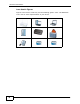
Document Conventions Icons Used in Figures Figures in this User’s Guide may use the following generic icons. The WAP3205 icon is not an exact representation of your device.
Safety Warnings Safety Warnings • Do NOT use this product near water, for example, in a wet basement or near a swimming pool. • Do NOT expose your device to dampness, dust or corrosive liquids. • Do NOT store things on the device. • Do NOT install, use, or service this device during a thunderstorm. There is a remote risk of electric shock from lightning. • Connect ONLY suitable accessories to the device. • Do NOT open the device or unit.
Safety Warnings 8 WAP3205 User’s Guide
Contents Overview Contents Overview User’s Guide ........................................................................................................................... 17 Getting to Know Your WAP3205 ................................................................................................ 19 WAP3205 Modes ....................................................................................................................... 23 Access Point Mode ...................................................
Contents Overview 10 WAP3205 User’s Guide
Table of Contents Table of Contents About This User's Guide .......................................................................................................... 3 Document Conventions............................................................................................................ 5 Safety Warnings........................................................................................................................ 7 Contents Overview .......................................................
Table of Contents 4.3 What You Need to Know ...................................................................................................... 34 4.4 Setting your WAP3205 to Client Mode ................................................................................ 34 4.5 Client Mode Status Screen .................................................................................................. 35 4.6 Wireless LAN Profile Screen .........................................................................
Table of Contents 8.3.1 Push Button Configuration (PBC) .............................................................................. 74 8.3.2 PIN Configuration ....................................................................................................... 75 8.4 Enabling and Configuring Wireless Security (No WPS) ...................................................... 77 8.4.1 Configure Your Notebook ........................................................................................... 79 8.
Table of Contents Chapter 11 LAN......................................................................................................................................... 117 11.1 Overview ...........................................................................................................................117 11.2 What You Can Do .............................................................................................................117 11.3 What You Need To Know ...................................
Table of Contents Appendix F Legal Information .............................................................................................. 215 Appendix G Open Software Announcements....................................................................... 219 Index.......................................................................................................................................
Table of Contents 16 WAP3205 User’s Guide
P ART I User’s Guide 17
CHAPTER 1 Getting to Know Your WAP3205 1.1 Overview This chapter introduces the main features and applications of the WAP3205. The WAP3205 extends the range of your existing wired network without additional wiring, providing easy network access to mobile users. You can set up a wireless network with other IEEE 802.11b/g/n compatible devices. 1.2 Applications Your can have the following networks on the WAP3205: • Wired.
Chapter 1 Getting to Know Your WAP3205 • WPS (Wi-Fi Protected Setup) button. You can use the WPS button or the WPS section of the Web Configurator to set up a wireless network with your WAP3205. 1.4 Good Habits for Managing the WAP3205 Do the following things regularly to make the WAP3205 more secure and to manage the WAP3205 more effectively. • Change the password. Use a password that’s not easy to guess and that consists of different types of characters, such as numbers and letters.
Chapter 1 Getting to Know Your WAP3205 Table 1 Front Panel LEDs and WPS Button LED COLOR STATUS DESCRIPTION WLAN Green On The WAP3205 is ready, but is not sending/ receiving data through the wireless LAN. Blinking The WAP3205 is sending/receiving data through the wireless LAN. Off The wireless LAN is not ready or has failed. On WPS is enabled. Blinking The WAP3205 is negotiating a WPS connection with a wireless client. Off The wireless LAN is not ready or has failed.
Chapter 1 Getting to Know Your WAP3205 22 WAP3205 User’s Guide
CHAPTER 2 WAP3205 Modes 2.1 Overview This chapter introduces the different modes available on your WAP3205. • Device mode. This is the operating mode of your WAP3205, or simply how the WAP3205 is being used in the network. 2.1.1 Device Modes This refers to the operating mode of the WAP3205, which can act as a: • Access Point. Use this mode if you want to extend your network by allowing network devices to connect to the WAP3205 wirelessly. Go to Section 3.
Chapter 2 WAP3205 Modes The following figure is a simple illustration of the device configuration modes of the WAP3205. Figure 3 Device Mode Example For more information on these modes and to change the mode of your WAP3205, refer to Chapter 12 on page 129. Note: Choose your device mode carefully to avoid having to change it later.
CHAPTER 3 Access Point Mode 3.1 Overview The WAP3205 is set to access point mode by default. In this mode your WAP3205 bridges a wired network (LAN) and wireless LAN (WLAN) in the same subnet. See the figure below for an example. Figure 4 Wireless Internet Access in Access Point Mode Note: See Chapter 8 on page 73 for an example of setting up a wireless network in Access Point mode. 3.2 What You Can Do • Use the Status screen (Section 3.4 on page 27) to view read-only information about your WAP3205.
Chapter 3 Access Point Mode 3.3.1 Setting your WAP3205 to AP Mode 1 Connect your computer to the LAN port of the WAP3205. 2 The default IP address of the WAP3205 is “192.168.1.2”. In this case, your computer must have an IP address in the range between “192.168.1.3” and “192.168.1.254”. 3 Click Start > Run on your computer in Windows. Type “cmd” in the dialog box. Enter “ipconfig” to show your computer’s IP address.
Chapter 3 Access Point Mode 3.4 AP Mode Status Screen Click to open the Status screen. Figure 6 Status Screen: Access Point Mode The following table describes the icons shown in the Status screen. Table 2 Status Screen Icon Key: Access Point Mode ICON DESCRIPTION Click this to go to the Home page. Click this icon to view copyright and a link for related product information. Click this icon to open the wizard. See Chapter 7 on page 61.
Chapter 3 Access Point Mode Table 2 Status Screen Icon Key: Access Point Mode (continued) ICON DESCRIPTION Click this icon to see the Configuration navigation menu. Click this icon to see the Maintenance navigation menu. The following table describes the labels shown in the Status screen. Table 3 Status Screen: Access Point Mode LABEL DESCRIPTION Logout Click this at any time to exit the Web Configurator. Device Information Host Name This is the WAP3205’s model name.
Chapter 3 Access Point Mode Table 3 Status Screen: Access Point Mode LABEL DESCRIPTION Status For the LAN ports, this field displays Down (line is down) or Up (line is up or connected). For the WLAN, it displays Up when the WLAN is enabled or Down when the WLAN is disabled. Rate For the LAN ports, this displays the port speed or N/A when the line is disconnected. For the WLAN, it displays the maximum transmission rate when the WLAN is enabled and N/A when the WLAN is disabled.
Chapter 3 Access Point Mode The following screen and table show the features you can configure in Access Point mode. Figure 7 Menu: Access Point Mode The following table describes the sub-menus. Table 4 Navigation Panel: Access Point Mode LINK TAB Status FUNCTION This screen shows the WAP3205’s general device, system and interface status information. Use this screen to access the wizard, and summary statistics tables.
Chapter 3 Access Point Mode Table 4 Navigation Panel: Access Point Mode LINK Wireless LAN LAN TAB FUNCTION General Use this screen to configure general wireless LAN settings. Security Use this screen to configure wireless security settings. MAC Filter Use the MAC filter screen to configure the WAP3205 to block access to devices or block the devices from accessing the WAP3205. Advanced This screen allows you to configure advanced wireless settings.
Chapter 3 Access Point Mode 32 WAP3205 User’s Guide
CHAPTER 4 Client Mode 4.1 Overview Your WAP3205 can act as a wireless client. In wireless client mode, it can connect to an existing network via an access point. Use this mode if you already have an access point or wireless router in your network. In the example below, one WAP3205 (A) is configured as a wireless client and another is used as an access point (B). The WAP3205 has two clients that need to connect to the Internet. The WAP3205 wirelessly connects to the available access point (B).
Chapter 4 Client Mode 4.3 What You Need to Know With the exception of the Wireless LAN screens, the LAN, Monitor, Configuration and Maintenance screens in Client mode are similar to the ones in Access Point Mode. See Chapter 11 on page 117 through Chapter 12 on page 121 of this User’s Guide. 4.4 Setting your WAP3205 to Client Mode 1 Connect your computer to the LAN port of the WAP3205. 2 The default IP address of the WAP3205 is “192.168.1.2”.
Chapter 4 Client Mode Note: The client mode IP address is always the same as the access point mode IP address. If you changed the IP address of your WAP3205 while in access point mode, use this IP address in client mode. 4.5 Client Mode Status Screen Click to open the status screen. Figure 10 Status: Client Mode The following table describes the labels shown in the Status screen. Table 5 Status Screen: Client Mode LABEL DESCRIPTION Logout Click this at any time to exit the Web Configurator.
Chapter 4 Client Mode Table 5 Status Screen: Client Mode LABEL DHCP DESCRIPTION This shows the LAN port’s DHCP role - Client or None. WLAN Information WLAN OP Mode This is the device mode (Section 2.1.1 on page 23) to which the WAP3205’s wireless LAN is set - Client Mode. MAC Address This shows the wireless adapter MAC Address of your device. Status This shows the current status of the Wireless LAN - ON. Name (SSID) This shows a descriptive name used to identify the WAP3205 in the wireless LAN.
Chapter 4 Client Mode Table 5 Status Screen: Client Mode LABEL DESCRIPTION Summary Packet Statistics Click Details... to go to the Monitor > Packet Statistics screen (Section 9.4 on page 96). Use this screen to view port status and packet specific statistics. 4.6 Wireless LAN Profile Screen Use this screen to view the wireless LAN profile settings of your WAP3205. Go to Configuration > Wireless LAN > Profile to open the following screen.
Chapter 4 Client Mode Table 6 Client Mode: WLAN > Profile (continued) LABEL DESCRIPTION Edit Select a profile and click this button to modify it. Activate Select a profile and click this button to enable it. Note: You can activate only one profile at a time. 4.6.1 Adding a New WLAN Profile Use this screen to create a new wireless LAN profile for your WAP3205. Click the Add button in the Configuration > Wireless LAN > Profile screen to open the following screen.
Chapter 4 Client Mode 4.6.1.1 No Security Use this screen if the access point to which you want to connect does not use encryption. Figure 13 Client Mode: WLAN > Profile: No Security The following table describes the labels in this screen. Table 8 Client Mode: WLAN > Profile: No Security LABEL DESCRIPTION Wireless Setup Profile Name Enter a descriptive name for this profile. Network Name (SSID) Enter the name of the access point to which you are connecting.
Chapter 4 Client Mode 4.6.1.2 Static WEP Use this screen if the access point to which you want to connect to uses WEP security mode. Figure 14 Client Mode: WLAN > Profile: WEP The following table describes the labels in this screen.. Table 9 Client Mode: WLAN > Profile: WEP LABEL DESCRIPTION Wireless Setup Profile Name Enter a descriptive name for this profile. Network Enter the name of the access point to which you are connecting.
Chapter 4 Client Mode Table 9 Client Mode: WLAN > Profile: WEP LABEL DESCRIPTION Authenticatio n Method Select Open or Shared Key from the drop-down list box. This field specifies whether the wireless clients have to provide the WEP key to log into the wireless network. Keep this setting at Open unless you want to force a key verification before communication between the wireless client and the ZyXEL Device occurs. Select Shared Key to force the clients to provide the WEP key prior to communication.
Chapter 4 Client Mode The following table describes the labels in this screen. . Table 10 Client Mode: WLAN > Profile: WPA-PSK/WPA2-PSK LABEL DESCRIPTION Wireless Setup Profile Name Enter a descriptive name for this profile. Network Name (SSID) Enter the name of the access point to which you are connecting. Security Security Mode Select WPA-PSK or WPA2-PSK to add strong security on this wireless network.
Chapter 4 Client Mode The following table describes the labels in this screen. Table 11 Client Mode: WLAN > Site Survey LABEL DESCRIPTION Station Site Survey # Select a wireless device and click Add Profile to open a configuration screen where you can add the selected wireless device to a profile and then enable it. SSID This displays the SSID of the wireless device. indicates the wireless device is added to an activated profile and the WAP3205 is connecting to it.
Chapter 4 Client Mode The following table describes the labels in this screen. Table 12 Client Mode: WLAN > WPS LABEL DESCRIPTION Station Site Survey # Use the radio button to select the wireless device to which you want to connect using WPS. SSID This displays the SSID of the wireless device. BSSID This displays the MAC address of the wireless device. Signal Strength This displays the strength of the wireless signal.
CHAPTER 5 Universal Repeater Mode 5.1 Overview In universal repeater mode, your WAP3205 can act as an access point and wireless client at the same time. The WAP3205 can connect to an existing network through another access point and also lets wireless clients connect to the network through it. This helps you expand wireless coverage when you have an access point or wireless router already in your network. In the example below, the WAP3205 (A) is configured as a universal repeater.
Chapter 5 Universal Repeater Mode • Use other Wireless LAN screens (Chapter 10 on page 99) to configure the wireless settings and wireless security between the wireless clients and the WAP3205. 5.3 What You Need to Know With the exception of the Wireless LAN > Universal Repeater screen, other configuration screens in Universal Repeater mode are similar to the ones in Access Point Mode. See Chapter 11 on page 117 through Chapter 12 on page 121 of this User’s Guide. 5.
Chapter 5 Universal Repeater Mode 7 To set your WAP3205 to Universal Repeater Mode, on the left of the screen, click Maintenance > Sys OP Mode and select Universal Repeater Mode. Figure 19 Changing to Universal Repeater mode Note: You have to log in to the Web Configurator again when you change modes. As soon as you do, your WAP3205 is already in Universal Repeater mode. Note: The universal repeater mode IP address is always the same as the access point mode IP address.
Chapter 5 Universal Repeater Mode 5.5 Universal Repeater Mode Status Screen Click to open the status screen. Figure 20 Status: Universal Repeater Mode The following table describes the labels shown in the Status screen. Table 13 Status Screen: Universal Repeater Mode LABEL DESCRIPTION Logout Click this at any time to exit the Web Configurator. Device Information Host Name This is the WAP3205’s model name. Firmware Version This is the firmware version and the date created.
Chapter 5 Universal Repeater Mode Table 13 Status Screen: Universal Repeater Mode LABEL DHCP DESCRIPTION This shows the LAN port’s DHCP role - Client or None. WLAN Information WLAN OP Mode This is the device mode (Section 2.1.1 on page 23) to which the WAP3205’s wireless LAN is set - Universal Repeater Mode. MAC Address This shows the wireless adapter MAC Address of your device. Status This shows the current status of the Wireless LAN - ON.
Chapter 5 Universal Repeater Mode Table 13 Status Screen: Universal Repeater Mode LABEL DESCRIPTION Memory Usage This shows what percentage of the heap memory the WAP3205 is using. System Setting Configuration Mode This shows the web configurator mode you are viewing - Expert. Summary Packet Statistics Click Details... to go to the Monitor > Packet Statistics screen (Section 9.4 on page 96). Use this screen to view port status and packet specific statistics. WLAN Station Status Click Details...
Chapter 5 Universal Repeater Mode 5.6.1 No Security Figure 21 Universal Repeater Mode: Wireless LAN > Universal Repeater: No Security The following table describes the labels in this screen. Table 14 Universal Repeater Mode: Wireless LAN > Universal Repeater: No Security LABEL DESCRIPTION Universal Repeater Parameters Enable Select this option to have the WAP3205 connect to the specified access point. SSID Enter the name of the access point to which you are connecting.
Chapter 5 Universal Repeater Mode 5.6.2 Static WEP Figure 22 Universal Repeater Mode: Wireless LAN > Universal Repeater: Static WEP The following table describes the labels in this screen. Table 15 Universal Repeater Mode: Wireless LAN > Universal Repeater: Static WEP LABEL DESCRIPTION Universal Repeater Parameters Enable Select this option to have the WAP3205 connect to the specified access point. SSID Enter the name of the access point to which you are connecting.
Chapter 5 Universal Repeater Mode Table 15 Universal Repeater Mode: Wireless LAN > Universal Repeater: Static WEP LABEL DESCRIPTION WEP Key 1 ~ WEP Key 4 The WEP keys are used to encrypt data. Both the WAP3205 and the access point must use the same WEP key for data transmission. If you chose HEX, enter 10 or 26 hexadecimal characters in the range of "A-F", "a-f" and "0-9" (for example, 11AA22BB33) for a 64-bit or 128-bit WEP key respectively.
Chapter 5 Universal Repeater Mode Table 16 Universal Repeater Mode: Wireless LAN > Universal Repeater: WPA(2)PSK LABEL DESCRIPTION Encryption Type Select the type of wireless encryption employed by the access point to which you want to connect. Pre-Shared Key WPA-PSK or WPA2-PSK uses a simple common password for authentication. Type the password employed by the access point to which you want to connect. 54 Apply Click Apply to save your changes back to the WAP3205.
CHAPTER 6 Introducing the Web Configurator 6.1 Overview This chapter describes how to access the WAP3205 Web Configurator and provides an overview of its screens. The Web Configurator is an HTML-based management interface that allows easy setup and management of the WAP3205 via Internet browser. Use Internet Explorer 6.0 and later or Safari 2.0 or later versions. The recommended screen resolution is 1024 by 768 pixels.
Chapter 6 Introducing the Web Configurator 4 After you’ve set your computer’s IP address, open a web browser such as Internet Explorer and type “http://192.168.1.2” as the web address in your web browser. 6.2.1 Login Screen The Web Configurator initially displays the following login screen. Figure 24 Login screen The following table describes the labels in this screen. Table 17 Login screen LABEL DESCRIPTION Password Type "1234" (default) as the password.
Chapter 6 Introducing the Web Configurator 6.2.2 Password Screen You should see a screen asking you to change your password (highly recommended) as shown next. Figure 25 Change Password Screen The following table describes the labels in this screen. Table 18 Change Password Screen LABEL DESCRIPTION New Password Type a new password. Retype to Confirm Retype the password for confirmation. Apply Click Apply to save your changes back to the WAP3205.
Chapter 6 Introducing the Web Configurator The Home screen displays as follows. Figure 26 Home Screen The following table describes the labels in this screen. Table 19 Home Screen LABEL DESCRIPTION Go Click this to open the Easy mode Web Configurator Status screen. Language Select a language to go to the Easy mode Web Configurator in that language and click Login. (This is just an example). This shows the current weather, either in celsius or fahrenheit, of the city you specify in Section 6.2.3.
Chapter 6 Introducing the Web Configurator The following table describes the labels in this screen. Table 20 Change Weather LABEL DESCRIPTION o Choose which temperature unit you want the WAP3205 to display. o C or F Change Location Select the location for which you want to know the weather. If the city you want is not listed, choose one that is closest to it. Finish Click this to apply the settings and refresh the date and time display. 6.2.3.
Chapter 6 Introducing the Web Configurator 6.3.1 Procedure to Use the Reset Button 60 1 Make sure the power LED is on. 2 Press the RESET button for longer than 1 second to restart/reboot the WAP3205. 3 Press the RESET button for longer than five seconds to set the WAP3205 back to its factory-default configurations.
CHAPTER 7 Connection Wizard 7.1 Overview This chapter provides information on the wizard setup screens in the Web Configurator. The Web Configurator’s wizard setup helps you change the system login password and configure your device’s operating mode and wireless settings. 7.2 Accessing the Wizard Launch your web browser and type "http://192.168.1.2" as the website address.
Chapter 7 Connection Wizard 7.2.1 Device Password Change the login password in the following screen. Enter the new password and retype it to confirm. Click Next to proceed with the Operation Mode screen. Figure 29 Device Password 7.2.2 Operation Mode Select in which device configuration mode you want the WAP3205 to operate. The WAP3205 can act as an access point (AP), wireless client or both at the same time. Click Next to configure wireless settings for the selected operation mode.
Chapter 7 Connection Wizard 7.2.3 Wireless Configuration Configure the wireless network settings on your WAP3205 in the following screen. The screen varies depending on the device configuration mode. 7.2.3.1 Universal Repeater Mode When the WAP3205 is in universal repeater mode, the WAP3205 works as an access point and wireless client at the same time. You can let wireless clients connect to another AP or wireless router through the WAP3205 to expand wireless coverage.
Chapter 7 Connection Wizard automatically. Enter the same security settings as the selected wireless device and click Next.
Chapter 7 Connection Wizard Figure 34 Wireless Security: WEP Settings for Wireless Clients Select the check box to use the same security settings (as the AP to which the WAP3205 is connecting) for communication between the WAP3205 and its wireless clients. Otherwise, clear the check box and use different SSID and wireless security settings for clients. Click Next. Figure 35 Wireless Configuration: Select a Network 7.2.3.2 Access Point Mode The WAP3205 is in access point mode by default.
Chapter 7 Connection Wizard Wireless Security: No Security Choose No Security in the Security mode field to let any wireless device within range access your wireless network. Figure 36 Wireless Security: No Security The following table describes the labels in this screen. Table 22 Wireless Security: No Security 66 LABEL DESCRIPTION Wireless Network Name (SSID) Enter a descriptive name (up to 32 printable 7-bit ASCII characters) for the wireless LAN.
Chapter 7 Connection Wizard Wireless Security: WPA-PSK/WPA2-PSK Choose WPA-PSK or WPA2-PSK security in the Security mode field to set up a password for your wireless network. Figure 37 Wireless Security: WPA-PSK/WPA2-PSK The following table describes the labels in this screen. Table 23 Wireless Security: WPA-PSK/WPA2-PSK LABEL DESCRIPTION Wireless Network Name (SSID) Enter a descriptive name (up to 32 printable 7-bit ASCII characters) for the wireless LAN.
Chapter 7 Connection Wizard Wireless Security: WEP Choose WEP security in the Security mode field to configure a WEP key for your wireless network. Figure 38 Wireless Security: WEP The following table describes the labels in this screen. Table 24 Wireless Security: WEP LABEL DESCRIPTION Wireless Network Name (SSID) Enter a descriptive name (up to 32 printable 7-bit ASCII characters) for the wireless LAN. Security mode Choose WEP security to enable data encryption using WEP keys.
Chapter 7 Connection Wizard Table 24 Wireless Security: WEP LABEL DESCRIPTION Exit Click this to close the wizard screen without saving. Back Click this to return to the previous screen. Next Click this to continue. 7.2.3.3 Client Mode In this mode, the WAP3205 is a wireless client. Clients can access the WAP3205 through a wired connection only. Select the wireless device to which you want the WAP3205 to connect and click Connect. Click Refresh to update the list of available wireless devices.
Chapter 7 Connection Wizard automatically. Enter the same security settings as the selected wireless device and click Next.
Chapter 7 Connection Wizard Figure 42 Wireless Security: WEP WAP3205 User’s Guide 71
Chapter 7 Connection Wizard 7.2.3.4 Wizard Setup Complete Click GO to reboot the WAP3205 and finish wizard configuration. Figure 43 Wizard Setup Complete Figure 44 Device Rebooting Congratulations! After the WAP3205 restarts, the login screen displays. You have successfully set up your WAP3205 to operate on your network and access the Internet. You are now ready to connect wirelessly to your WAP3205 and access the Internet.
CHAPTER 8 Tutorials 8.
Chapter 8 Tutorials 8.3 Configuring Wireless Security Using WPS This section gives you an example of how to set up wireless network using WPS. This example uses the WAP3205 as the AP and NWD-211AN as the wireless client which connects to a notebook. Note: The wireless client must be a WPS-aware device (for example, a WPS USB adapter or PCI card). There are two WPS methods for creating a secure connection. This tutorial shows you how to do both.
Chapter 8 Tutorials The following figure shows you how to set up wireless network and security by pressing a button on both WAP3205 and wireless client (the NWD-211AN in this example). Figure 46 Example WPS Process: PBC Method Wireless Client WITHIN 2 MINUTES SECURITY INFO COMMUNICATION 8.3.2 PIN Configuration When you use the PIN configuration method, you need to use both WAP3205’s configuration interface and the client’s utilities. 1 Launch your wireless client’s configuration utility.
Chapter 8 Tutorials The following figure shows you how to set up wireless network and security on WAP3205 and wireless client (NWD-211AN in this example) by using PIN method.
Chapter 8 Tutorials 8.4 Enabling and Configuring Wireless Security (No WPS) This example shows you how to configure wireless security settings with the following parameters on your WAP3205. SSID SSID_Example3 Channel Auto Security WPA-PSK (Pre-Shared Key: ThisismyWPA-PSKpre-sharedkey) Follow the steps below to configure the wireless settings on your WAP3205.
Chapter 8 Tutorials 4 Select the SSID (SSID_Example3) for which you want to configure the security. Set security mode to WPA-PSK and enter ThisismyWPA-PSKpre-sharedkey in the Pre-Shared Key field. Click Apply. Figure 49 Tutorial: Network > Wireless LAN > Security 5 Open the Status screen. Verify your wireless and wireless security settings under Device Information and check if the WLAN connection is up under Interface Status.
Chapter 8 Tutorials 8.4.1 Configure Your Notebook Note: We use the ZyXEL NWD-211AN wireless adapter utility screens as an example for the wireless client. The screens may vary for different models. 1 The WAP3205 supports IEEE 802.11b, IEEE 802.11g and IEEE 802.11n wireless clients. Make sure that your notebook or computer’s wireless adapter supports one of these standards. 2 Wireless adapters come with software sometimes called a “utility” that you install on your computer.
Chapter 8 Tutorials 6 The Confirm Save window appears. Check your settings and click Save to continue. Figure 53 Confirm Save 7 Check the status of your wireless connection in the screen below. If your wireless connection is weak or you have no connection, see the Troubleshooting section of this User’s Guide. Figure 54 Link Status If your connection is successful, open your Internet browser and enter http:// www.zyxel.com or the URL of any other web site in the address bar.
Chapter 8 Tutorials Clients can associate only with the SSIDs for which they have the correct security settings. Clients using different SSIDs can access the Internet and the wired network behind the WAP3205 (such as a printer), but they cannot listen to each other’s traffic. For example, you may set up three wireless networks (A, B and C) in your office. A is for workers, B is for guests and C is specific to a VoIP device in the meeting room. A SSID_Worker C SSID_VoIP B SSID_Guest 8.5.
Chapter 8 Tutorials 82 2 The default IP address of the WAP3205 is “192.168.1.2”. In this case, your computer must have an IP address in the range between “192.168.1.3” and “192.168.1.254”. 3 Click Start > Run on your computer in Windows. Type “cmd” in the dialog box. Enter “ipconfig” to show your computer’s IP address. If your computer’s IP address is not in the correct range then see Appendix C on page 167 for information on changing your computer’s IP address.
Chapter 8 Tutorials 9 Click the Security tab to configure security settings for each SSID. Select SSID_Worker from the SSID drop-down list. Configure the screen as follows. Click Apply. 10 Select SSID_Guest from the SSID drop-down list. Configure the screen as follows. Click Apply.
Chapter 8 Tutorials 11 Select SSID_VoIP from the SSID drop-down list. Configure the screen as follows. Click Apply. 12 Click the MAC Filter tab to configure MAC filtering for the SSID_VoIP wireless network. Select SSID_VoIP from the SSID drop-down list and select Allow in the Policy field. Enter the VoIP device’s MAC address in the Add a station Mac Address field and click Apply to allow only the VoIP device to associate with the WAP3205 using this SSID. 8.
Chapter 8 Tutorials repeater mode and then associate the WAP3205 with the AP or wireless router. The WAP3205 must be within the transmission range of the AP or wireless router. 1 Connect your computer to the LAN port of the WAP3205 using an Ethernet cable. 2 The default IP address of the WAP3205 is “192.168.1.2”. In this case, your computer must have an IP address in the range between “192.168.1.3” and “192.168.1.254”. 3 Click Start > Run on your computer in Windows. Type “cmd” in the dialog box.
Chapter 8 Tutorials 10 Go to Configuration > Network > Wireless LAN > Universal Repeater to connect the WAP3205 wirelessly to an AP. Select Enable. Enter the SSID of the existing AP or wireless router to which you want to connect (“SSIDofMyAP” in this example). Enter the wireless security settings which are the same as those on the existing AP or wireless router to access it (WPA-PSK and “KeyofMyWirelessNetwork” in this example). Click Apply.
Chapter 8 Tutorials 12 Go to the Status screen. If the WAP3205 has successfully connected to an AP or wireless router, it displays the SSID and MAC address of the AP or wireless router in the field next to WLAN Station Status under Device Information. To check whether a wireless client is currently connecting to the WAP3205, click the WLAN Station Status (Details...) hyperlink under Summary in the Status screen or Monitor > WLAN Station Status. See Section 9.5 on page 98 for more information.
Chapter 8 Tutorials 8.7 Connecting the WAP3205 (in Client Mode) to an AP or Wireless Router If you have an access point or wireless router with Internet access deployed in your network already, and you want to use the WAP3205 as a wireless client to connect to the existing AP or wireless router, set the WAP3205 to client mode. The WAP3205 then acts as a wireless client. Your device, such as a computer, can connect to the WAP3205 through a wired connection to access the Internet.
Chapter 8 Tutorials 10 To connect to a specific wireless network, you can manually create a wireless profile or use the site survey tool to associate with it. 8.7.1 Connecting to a Wireless Network Using Site Survey 1 Go to Configuration > Network > Wireless LAN > Site Survey. The WAP3205 automatically scans for and connects to an available wireless network. The green check icon indicates the wireless device to which the WAP3205 is connecting.
Chapter 8 Tutorials 3 The new profile entry displays in the Profile screen. The green check icon means this profile is active and the WAP3205 is associating with the specified wireless network. 8.7.2 Connecting to a Wireless Network Using a Profile 90 1 Go to Configuration > Network > Wireless LAN > Profile. Click Add to manually create a wireless LAN profile. 2 Enter a descriptive profile name and the SSID and security settings of the wireless device to which you want to connect. Click Apply.
Chapter 8 Tutorials 3 The new profile entry displays in the Profile screen. To enable a profile, select the corresponding radio button and click Activate. The green check icon means this profile is active and the WAP3205 is associating with the specified wireless network. 8.7.3 Deploying the WAP3205 in your Network 1 After you finish configuring the operating mode and wireless settings on the WAP3205, disconnect the computer from the WAP3205 and change its TCP/IP settings back to the previous ones.
Chapter 8 Tutorials 92 WAP3205 User’s Guide
P ART II Technical Reference 93
CHAPTER 9 Monitor 9.1 Overview This chapter discusses read-only information related to the device state of the WAP3205. Note: To access the Monitor screens, you can also click the links in the Summary table of the Status screen to view the packets sent/received as well as the status of clients connected to the WAP3205. 9.2 What You Can Do • Use the Log screen (Section 9.3 on page 95) to view the logs for the categories such as system maintenance, system errors, and so on.
Chapter 9 Monitor Click Monitor > Log. Figure 55 Monitor > Log The following table describes the labels in this screen. Table 25 Monitor > Log LABEL DESCRIPTION # This field is a sequential value and is not associated with a specific entry. Time This field displays the time the log was recorded. Message This field states the reason for the log. Refresh Click Refresh to renew the log screen. Clear Click Clear to delete all the logs. 9.4 Packet Statistics Click the Packet Statistics (Details...
Chapter 9 Monitor packet specific statistics and the "system up time". The Poll Interval(s) field is configurable and is used for refreshing the screen. Figure 56 Summary: Packet Statistics The following table describes the labels in this screen. Table 26 Summary: Packet Statistics LABEL DESCRIPTION Port This is the WAP3205’s port type. Status For the LAN ports, this displays the port speed or Down when the line is disconnected.
Chapter 9 Monitor 9.5 WLAN Station Status Click the WLAN Station Status (Details...) hyperlink in the Status screen or Monitor > WLAN Station Status. View the wireless stations that are currently associated to the WAP3205 in the Association List. Association means that a wireless client (for example, your network or computer with a wireless network card) has connected successfully to the AP (or wireless router) using the same SSID, channel and security settings.
CHAPTER 10 Wireless LAN 10.1 Overview This chapter discusses how to configure the wireless network settings in your WAP3205. See the appendices for more detailed information about wireless networks. The following figure provides an example of a wireless network. Figure 58 Example of a Wireless Network A B The wireless network is the part in the blue circle. In this wireless network, devices A and B are called wireless clients.
Chapter 10 Wireless LAN 10.2 What You Can Do • Use the General screen (Section 10.4 on page 103) to enter the SSID, enable intra-BSS traffic and select the channel. • Use the Security screen (Section 10.5 on page 104) to configure wireless security between the WAP3205 and the wireless clients. • Use the MAC Filter screen (Section 10.6 on page 108) to allow or deny wireless stations based on their MAC addresses from connecting to the WAP3205. • Use the Advanced screen (Section 10.
Chapter 10 Wireless LAN 10.3.1.1 SSID Normally, the AP acts like a beacon and regularly broadcasts the SSID in the area. You can hide the SSID instead, in which case the AP does not broadcast the SSID. In addition, you should change the default SSID to something that is difficult to guess. This type of security is fairly weak, however, because there are ways for unauthorized devices to get the SSID. In addition, unauthorized devices can still see the information that is sent in the wireless network. 10.3.
Chapter 10 Wireless LAN The types of encryption you can choose depend on the type of user authentication. Table 28 Types of Encryption for Each Type of Authentication NO AUTHENTICATION Weakest No Security WEP WPA-PSK Strongest WPA2-PSK Usually, you should set up the strongest encryption that every wireless client in the wireless network supports. Suppose the wireless network has two wireless clients. Device A only supports WEP, and device B supports WEP and WPA-PSK.
Chapter 10 Wireless LAN 10.4 General Wireless LAN Screen Use this screen to enter the SSID, select the channel and enable intra-BSS traffic. Note: If you are configuring the WAP3205 from a computer connected to the wireless LAN and you change the WAP3205’s SSID, channel or security settings, you will lose your wireless connection when you press Apply to confirm. You must then change the wireless settings of your computer to match the WAP3205’s new settings.
Chapter 10 Wireless LAN Table 29 Network > Wireless LAN > General LABEL Enable Intra-BSS Traffic DESCRIPTION A Basic Service Set (BSS) exists when all communications between wireless clients or between a wireless client and a wired network client go through one access point (AP). Intra-BSS traffic is traffic between wireless clients in the BSS. When IntraBSS is enabled, wireless clients can access the wired network and communicate with each other.
Chapter 10 Wireless LAN Note: If you do not enable any wireless security on your WAP3205, your network is accessible to any wireless networking device that is within range. Figure 60 Network > Wireless LAN > Security: No Security The following table describes the labels in this screen. Table 30 Network > Wireless LAN > Security: No Security LABEL DESCRIPTION SSID Select the SSID for which you want to configure the security. Security Mode Choose No Security from the drop-down list box.
Chapter 10 Wireless LAN Select Static WEP from the Security Mode list. Figure 61 Network > Wireless LAN > Security: Static WEP The following table describes the wireless LAN security labels in this screen. Table 31 Network > Wireless LAN > Security: Static WEP LABEL DESCRIPTION SSID Select the SSID for which you want to configure the security. Security Mode Select Static WEP to enable data encryption. PassPhrase Enter a Passphrase (up to 26 printable characters) and click Generate.
Chapter 10 Wireless LAN Table 31 Network > Wireless LAN > Security: Static WEP LABEL DESCRIPTION Hex Select this option in order to enter hexadecimal characters as a WEP key. The preceding "0x", that identifies a hexadecimal key, is entered automatically. Key 1 to Key 4 The WEP keys are used to encrypt data. Both the WAP3205 and the wireless stations must use the same WEP key for data transmission. If you chose 64-bit WEP, then enter any 5 ASCII characters or 10 hexadecimal characters ("0-9", "A-F").
Chapter 10 Wireless LAN Table 32 Network > Wireless LAN > Security: WPA-PSK/WPA2-PSK LABEL DESCRIPTION Pre-Shared Key WPA-PSK/WPA2-PSK uses a simple common password for authentication. Type a pre-shared key from 8 to 63 case-sensitive keyboard characters. Group Key Update Timer The Group Key Update Timer is the rate at which the AP sends a new group key out to all clients. The default is 3600 seconds (60 minutes). Apply Click Apply to save your changes back to the WAP3205.
Chapter 10 Wireless LAN Table 33 Network > Wireless LAN > MAC Filter LABEL DESCRIPTION Policy Define the filter action for the list of MAC addresses in the MAC Address table. Select Disable to deactivate the MAC filtering rule you configure below. Select Allow to permit access to the WAP3205, MAC addresses not listed will be denied access to the WAP3205.
Chapter 10 Wireless LAN The following table describes the labels in this screen. Table 34 Network > Wireless LAN > Advanced LABEL DESCRIPTION RTS/CTS Threshold Data with its frame size larger than this value will perform the RTS (Request To Send)/CTS (Clear To Send) handshake. Enter a value between 256 and 2432. Fragmentatio n Threshold The threshold (number of bytes) for the fragmentation boundary for directed messages. It is the maximum data fragment size that can be sent.
Chapter 10 Wireless LAN Table 34 Network > Wireless LAN > Advanced LABEL DESCRIPTION Apply Click Apply to save your changes back to the WAP3205. Cancel Click Cancel to reload the previous configuration for this screen. 10.8 Quality of Service (QoS) Screen The QoS screen allows you to automatically give a service (such as VoIP and video) a priority level. Click Network > Wireless LAN > QoS. The following screen appears.
Chapter 10 Wireless LAN Note: With WPS, wireless clients can only connect to the wireless network using the first SSID on the WAP3205. Figure 66 Network > Wireless LAN > WPS The following table describes the labels in this screen. Table 36 Network > Wireless LAN > WPS LABEL DESCRIPTION WPS Setup Enable WPS Select this to enable the WPS feature. PIN Number This displays a PIN number last time system generated. Click Generate to generate a new PIN number.
Chapter 10 Wireless LAN 10.10 WPS Station Screen Use this screen when you want to add a wireless station using WPS. To open this screen, click Network > Wireless LAN > WPS Station tab. Note: After you click Push Button on this screen, you have to press a similar button in the wireless station utility within 2 minutes. To add the second wireless station, you have to press these buttons on both device and the wireless station again after the first 2 minutes.
Chapter 10 Wireless LAN on or off on certain days and at certain times. To open this screen, click Network > Wireless LAN > Scheduling tab. Figure 68 Network > Wireless LAN > Scheduling The following table describes the labels in this screen. Table 38 Network > Wireless LAN > Scheduling LABEL DESCRIPTION Wireless LAN Scheduling Enable Wireless LAN Scheduling Select this to enable Wireless LAN scheduling.
Chapter 10 Wireless LAN 10.12 WDS Screen A Wireless Distribution System (WDS) is a wireless connection between two or more APs. Use this screen to set the operating mode of your WAP3205 to AP + Bridge or Bridge and establish wireless links with other APs. You need to know the MAC address of the peer device, which also must be in bridge mode. Note: You must enable the same wireless security settings on the WAP3205 and on all wireless clients that you want to associate with it.
Chapter 10 Wireless LAN Table 39 Network > Wireless LAN > WDS LABEL DESCRIPTION Phy Mode Select the Phy mode you want the WAP3205 to use. This dictates the maximum size of packets during data transmission. This field is not available when you select Disable in the Basic Setting field. Remote MAC Address This is the MAC address of the peer device that your WAP3205 wants to make a bridge connection with. You can connect to up to 4 peer devices.
CHAPTER 11 LAN 11.1 Overview This chapter describes how to configure LAN settings. A Local Area Network (LAN) is a shared communication system to which many computers are attached. A LAN is a computer network limited to the immediate area, usually the same building or floor of a building. The LAN screens can help you configure a LAN DHCP server, manage IP addresses, and partition your physical network into logical networks. Figure 70 LAN Example The LAN screens can help you manage IP addresses. 11.
Chapter 11 LAN 11.3 What You Need To Know There are two separate IP networks, one inside the LAN network and the other outside the WAN network as shown next. Figure 71 LAN and WAN IP Addresses The LAN parameters of the WAP3205 are preset in the factory with the following values: • IP address of 192.168.1.2 with subnet mask of 255.255.255.0 (24 bits) 11.3.1 LAN TCP/IP The WAP3205 has built-in DHCP server capability that assigns IP addresses and DNS servers to systems that support DHCP client capability.
Chapter 11 LAN 11.4 LAN IP Screen Use this screen to change the IP address for your WAP3205. Click Network > LAN > IP. Figure 72 Network > LAN > IP The following table describes the labels in this screen. Table 40 Network > LAN > IP LABEL DESCRIPTION Get from DHCP Server Click this to deploy the WAP3205 as a DHCP client in the network. When you enable this, the WAP3205 gets its IP address from the network’s DHCP server (for example, your ISP or router).
Chapter 11 LAN Table 40 Network > LAN > IP LABEL DESCRIPTION DNS Assignment First DNS Server Second DNS Server Select From ISP if your ISP or router to which the WAP3205 connects dynamically assigns DNS server information (and the WAP3205's WAN IP address). The field to the right displays the (read-only) DNS server IP address that the ISP assigns. Select User-Defined if you have the IP address of a DNS server. Enter the DNS server's IP address in the field to the right.
CHAPTER 12 Maintenance 12.1 Overview This chapter provides information on the Maintenance screens. 12.2 What You Can Do • Use the General screen (Section 12.3 on page 122) to set the timeout period of the management session. • Use the Password screen (Section 12.4 on page 122) to change your WAP3205’s system password. • Use the Time screen (Section 12.5 on page 123) to change your WAP3205’s time and date. • Use the Firmware Upgrade screen (Section 12.6 on page 125) to upload firmware to your WAP3205.
Chapter 12 Maintenance 12.3 General Screen Use this screen to set the management session timeout period. Click Maintenance > General. The following screen displays. Figure 74 Maintenance > General The following table describes the labels in this screen. Table 42 Maintenance > General LABEL DESCRIPTION Administrator Inactivity Timer Type how many minutes a management session can be left idle before the session times out. The default is 5 minutes.
Chapter 12 Maintenance The following table describes the labels in this screen. Table 43 Maintenance > Password LABEL DESCRIPTION Password Setup Change your WAP3205’s password (recommended) using the fields as shown. Old Password Type the default password or the existing password you use to access the system in this field. New Password Type your new system password (up to 30 characters). Note that as you type a password, the screen displays an asterisk (*) for each character you type.
Chapter 12 Maintenance he following table describes the labels in this screen. Table 44 Maintenance > Time LABEL DESCRIPTION Current Time and Date Current Time This field displays the time of your WAP3205. Each time you reload this page, the WAP3205 synchronizes the time with the time server. Current Date This field displays the date of your WAP3205. Each time you reload this page, the WAP3205 synchronizes the date with the time server.
Chapter 12 Maintenance Table 44 Maintenance > Time LABEL DESCRIPTION Start Date Configure the day and time when Daylight Saving Time starts if you selected Daylight Savings. The o'clock field uses the 24 hour format. Here are a couple of examples: Daylight Saving Time starts in most parts of the United States on the second Sunday of March. Each time zone in the United States starts using Daylight Saving Time at 2 A.M. local time.
Chapter 12 Maintenance Click Maintenance > Firmware Upgrade. Follow the instructions in this screen to upload firmware to your WAP3205. Figure 77 Maintenance > Firmware Upgrade The following table describes the labels in this screen. Table 45 Maintenance > Firmware Upgrade LABEL DESCRIPTION Upgrade Firmware File Path Type in the location of the file you want to upload in this field or click Browse... to find it. Browse... Click Browse... to find the .bin file you want to upload.
Chapter 12 Maintenance After you see the Firmware Upload In Process screen, wait two minutes before logging into the WAP3205 again. The WAP3205 automatically restarts in this time causing a temporary network disconnect. In some operating systems, you may see the following icon on your desktop. Figure 78 Network Temporarily Disconnected After two minutes, log in again and check your new firmware version in the Status screen. If the upload was not successful, an error message appears.
Chapter 12 Maintenance Click Maintenance > Backup/Restore. Information related to factory defaults, backup configuration, and restoring configuration appears as shown next. Figure 79 Maintenance > Backup/Restore The following table describes the labels in this screen. Table 46 Maintenance > Backup/Restore LABEL DESCRIPTION Backup Click Backup to save the WAP3205’s current configuration to your computer. File Path Type in the location of the file you want to upload in this field or click Browse...
Chapter 12 Maintenance Note: If you uploaded the default configuration file you may need to change the IP address of your computer to be in the same subnet as that of the default WAP3205 IP address (192.168.1.2). See Appendix C on page 167 for details on how to set up your computer’s IP address. 12.8 Reset/Restart Screen System restart allows you to reboot the WAP3205 without turning the power off. Click Maintenance > Reset/Restart to open the following screen.
Chapter 12 Maintenance Access Point An access point enabled all ethernet ports to be bridged together and be in the same subnet. To connect to the Internet, another device, such as a router, is required. Figure 81 Access Point Mode Client WAP3205 in client mode connects to an existing access point wirelessly. It acts just like a wireless client in notebooks/computers.
Chapter 12 Maintenance 12.10 Sys Op Mode Screen Use this screen to select how you want to use your WAP3205. Figure 84 Maintenance > Sys OP Mode The following table describes the labels in the General screen. Table 47 Maintenance > Sys OP Mode LABEL DESCRIPTION System Operation Mode Access Point Select Access Point Mode if your device bridges traffic between clients on the same network. • • Client Mode Select Client Mode if your device needs a wireless client to connect to an existing access point.
Chapter 12 Maintenance 132 WAP3205 User’s Guide
CHAPTER 13 Troubleshooting This chapter offers some suggestions to solve problems you might encounter. The potential problems are divided into the following categories. • Power, Hardware Connections, and LEDs • WAP3205 Access and Login • Internet Access • Resetting the WAP3205 to Its Factory Defaults • Wireless Router/AP Troubleshooting 13.1 Power, Hardware Connections, and LEDs The WAP3205 does not turn on. None of the LEDs turn on.
Chapter 13 Troubleshooting 3 Inspect your cables for damage. Contact the vendor to replace any damaged cables. 4 Disconnect and re-connect the power adaptor to the WAP3205. 5 If the problem continues, contact the vendor. 13.2 WAP3205 Access and Login I don’t know the IP address of my WAP3205. 1 The default IP address is 192.168.1.2. 2 If you changed the IP address and have forgotten it, • and your WAP3205 is a DHCP client, you can find your IP address from the DHCP server.
Chapter 13 Troubleshooting • If you changed the IP address and have forgotten it, see the troubleshooting suggestions for I don’t know the IP address of my WAP3205. 2 Check the hardware connections, and make sure the LEDs are behaving as expected. See the Quick Start Guide. 3 Make sure your Internet browser does not block pop-up windows and has JavaScripts and Java enabled. See Appendix A on page 143. 4 Make sure your computer is in the same subnet as the WAP3205.
Chapter 13 Troubleshooting 13.3 Internet Access I cannot access the Internet. 1 Check the hardware connections, and make sure the LEDs are behaving as expected. See the Quick Start Guide. 2 Make sure the WAP3205 is connected to a broadband modem or router with Internet access. 3 If you are trying to access the Internet wirelessly, make sure the wireless settings in the wireless client are the same as the settings in the AP.
Chapter 13 Troubleshooting The Internet connection is slow or intermittent. 1 There might be a lot of traffic on the network. Look at the LEDs, and check Section 1.5 on page 20. If the WAP3205 is sending or receiving a lot of information, try closing some programs that use the Internet, especially peer-to-peer applications. 2 Check the signal strength.
Chapter 13 Troubleshooting If the WAP3205 restarts automatically, wait for the WAP3205 to finish restarting, and log in to the Web Configurator. The password is “1234”. If the WAP3205 does not restart automatically, disconnect and reconnect the WAP3205’s power. Then, follow the directions above again. 13.5 Wireless Router/AP Troubleshooting I cannot access the WAP3205 or ping any computer from the WLAN (wireless AP or router).
CHAPTER 14 Product Specifications The following tables summarize the WAP3205’s hardware and firmware features. Table 48 Hardware Features Dimensions (W x D x H) 162 mm x 115 mm x 33 mm Weight 245 g Power Specification Input: 100~240 V AC, 50~60 Hz Output: 12 V DC 1A Two Ethernet ports Auto-negotiating: 10 Mbps, 100 Mbps in either half-duplex or fullduplex mode. Auto-crossover: Use either crossover or straight-through Ethernet cables.
Chapter 14 Product Specifications Table 49 Firmware Features FEATURE DESCRIPTION Device Management Use the Web Configurator to easily configure the rich range of features on the WAP3205. Wireless Functionality Allows IEEE 802.11b, IEEE 802.11g and/or IEEE 802.11n wireless clients to connect to the WAP3205 wirelessly. Enable wireless security (WPA(2)-PSK) and/or MAC filtering to protect your wireless network. Note: The WAP3205 may be prone to RF (Radio Frequency) interference from other 2.
Chapter 14 Product Specifications 4 Make sure the screws are snugly fastened to the wall. They need to hold the weight of the WAP3205 with the connection cables. 5 Align the holes on the back of the WAP3205 with the screws on the wall. Hang the WAP3205 on the screws. Figure 85 Wall-mounting Example The following are dimensions of an M4 tap screw and masonry plug used for wall mounting. All measurements are in millimeters (mm).
Chapter 14 Product Specifications 142 WAP3205 User’s Guide
APPENDIX A Pop-up Windows, JavaScripts and Java Permissions In order to use the web configurator you need to allow: • Web browser pop-up windows from your device. • JavaScripts (enabled by default). • Java permissions (enabled by default). Note: The screens used below belong to Internet Explorer version 6, 7 and 8. Screens for other Internet Explorer versions may vary. Internet Explorer Pop-up Blockers You may have to disable pop-up blocking to log into your device.
Appendix A Pop-up Windows, JavaScripts and Java Permissions 1 In Internet Explorer, select Tools, Internet Options, Privacy. 2 Clear the Block pop-ups check box in the Pop-up Blocker section of the screen. This disables any web pop-up blockers you may have enabled. Figure 88 Internet Options: Privacy 3 Click Apply to save this setting. Enable Pop-up Blockers with Exceptions Alternatively, if you only want to allow pop-up windows from your device, see the following steps.
Appendix A Pop-up Windows, JavaScripts and Java Permissions 2 Select Settings…to open the Pop-up Blocker Settings screen. Figure 89 Internet Options: Privacy 3 Type the IP address of your device (the web page that you do not want to have blocked) with the prefix “http://”. For example, http://192.168.167.1.
Appendix A Pop-up Windows, JavaScripts and Java Permissions 4 Click Add to move the IP address to the list of Allowed sites. Figure 90 Pop-up Blocker Settings 5 Click Close to return to the Privacy screen. 6 Click Apply to save this setting. JavaScripts If pages of the web configurator do not display properly in Internet Explorer, check that JavaScripts are allowed.
Appendix A Pop-up Windows, JavaScripts and Java Permissions 1 In Internet Explorer, click Tools, Internet Options and then the Security tab. Figure 91 Internet Options: Security 2 Click the Custom Level... button. 3 Scroll down to Scripting. 4 Under Active scripting make sure that Enable is selected (the default). 5 Under Scripting of Java applets make sure that Enable is selected (the default).
Appendix A Pop-up Windows, JavaScripts and Java Permissions 6 Click OK to close the window. Figure 92 Security Settings - Java Scripting Java Permissions 148 1 From Internet Explorer, click Tools, Internet Options and then the Security tab. 2 Click the Custom Level... button. 3 Scroll down to Microsoft VM. 4 Under Java permissions make sure that a safety level is selected.
Appendix A Pop-up Windows, JavaScripts and Java Permissions 5 Click OK to close the window. Figure 93 Security Settings - Java JAVA (Sun) 1 From Internet Explorer, click Tools, Internet Options and then the Advanced tab. 2 Make sure that Use Java 2 for
Appendix A Pop-up Windows, JavaScripts and Java Permissions 3 Click OK to close the window. Figure 94 Java (Sun) Mozilla Firefox Mozilla Firefox 2.0 screens are used here. Screens for other versions may vary slightly. The steps below apply to Mozilla Firefox 3.0 as well. You can enable Java, Javascripts and pop-ups in one screen. Click Tools, then click Options in the screen that appears.
Appendix A Pop-up Windows, JavaScripts and Java Permissions Click Content to show the screen below. Select the check boxes as shown in the following screen. Figure 96 Mozilla Firefox Content Security Opera Opera 10 screens are used here. Screens for other versions may vary slightly.
Appendix A Pop-up Windows, JavaScripts and Java Permissions Allowing Pop-Ups From Opera, click Tools, then Preferences. In the General tab, go to Choose how you prefer to handle pop-ups and select Open all pop-ups.
Appendix A Pop-up Windows, JavaScripts and Java Permissions Enabling Java From Opera, click Tools, then Preferences. In the Advanced tab, select Content from the left-side menu. Select the check boxes as shown in the following screen. Figure 98 Opera: Enabling Java To customize JavaScript behavior in the Opera browser, click JavaScript Options. Figure 99 Opera: JavaScript Options Select the items you want Opera’s JavaScript to apply.
Appendix A Pop-up Windows, JavaScripts and Java Permissions 154 WAP3205 User’s Guide
APPENDIX B IP Addresses and Subnetting This appendix introduces IP addresses and subnet masks. IP addresses identify individual devices on a network. Every networking device (including computers, servers, routers, printers, etc.) needs an IP address to communicate across the network. These networking devices are also known as hosts. Subnet masks determine the maximum number of possible hosts on a network. You can also use subnet masks to divide one network into multiple sub-networks.
Appendix B IP Addresses and Subnetting The following figure shows an example IP address in which the first three octets (192.168.1) are the network number, and the fourth octet (16) is the host ID. Figure 100 Network Number and Host ID How much of the IP address is the network number and how much is the host ID varies according to the subnet mask.
Appendix B IP Addresses and Subnetting By convention, subnet masks always consist of a continuous sequence of ones beginning from the leftmost bit of the mask, followed by a continuous sequence of zeros, for a total number of 32 bits. Subnet masks can be referred to by the size of the network number part (the bits with a “1” value). For example, an “8-bit mask” means that the first 8 bits of the mask are ones and the remaining 24 bits are zeroes.
Appendix B IP Addresses and Subnetting Notation Since the mask is always a continuous number of ones beginning from the left, followed by a continuous number of zeros for the remainder of the 32 bit mask, you can simply specify the number of ones instead of writing the value of each octet. This is usually specified by writing a “/” followed by the number of bits in the mask after the address. For example, 192.1.1.0 /25 is equivalent to saying 192.1.1.0 with subnet mask 255.255.255.128.
Appendix B IP Addresses and Subnetting The following figure shows the company network before subnetting. Figure 101 Subnetting Example: Before Subnetting You can “borrow” one of the host ID bits to divide the network 192.168.1.0 into two separate sub-networks. The subnet mask is now 25 bits (255.255.255.128 or /25). The “borrowed” host ID bit can have a value of either 0 or 1, allowing two subnets; 192.168.1.0 /25 and 192.168.1.128 /25. The following figure shows the company network after subnetting.
Appendix B IP Addresses and Subnetting In a 25-bit subnet the host ID has 7 bits, so each sub-network has a maximum of 27 – 2 or 126 possible hosts (a host ID of all zeroes is the subnet’s address itself, all ones is the subnet’s broadcast address). 192.168.1.0 with mask 255.255.255.128 is subnet A itself, and 192.168.1.127 with mask 255.255.255.128 is its broadcast address. Therefore, the lowest IP address that can be assigned to an actual host for subnet A is 192.168.1.1 and the highest is 192.168.1.126.
Appendix B IP Addresses and Subnetting Table 56 Subnet 3 IP/SUBNET MASK NETWORK NUMBER LAST OCTET BIT VALUE IP Address 192.168.1. 128 IP Address (Binary) 11000000.10101000.00000001. 10000000 Subnet Mask (Binary) 11111111.11111111.11111111. 11000000 Subnet Address: 192.168.1.128 Lowest Host ID: 192.168.1.129 Broadcast Address: 192.168.1.191 Highest Host ID: 192.168.1.190 Table 57 Subnet 4 IP/SUBNET MASK NETWORK NUMBER LAST OCTET BIT VALUE IP Address 192.168.1.
Appendix B IP Addresses and Subnetting Subnet Planning The following table is a summary for subnet planning on a network with a 24-bit network number. Table 59 24-bit Network Number Subnet Planning NO. “BORROWED” HOST BITS SUBNET MASK NO. SUBNETS NO. HOSTS PER SUBNET 1 255.255.255.128 (/25) 2 126 2 255.255.255.192 (/26) 4 62 3 255.255.255.224 (/27) 8 30 4 255.255.255.240 (/28) 16 14 5 255.255.255.248 (/29) 32 6 6 255.255.255.252 (/30) 64 2 7 255.255.255.
Appendix B IP Addresses and Subnetting addresses, follow their instructions in selecting the IP addresses and the subnet mask. If the ISP did not explicitly give you an IP network number, then most likely you have a single user account and the ISP will assign you a dynamic IP address when the connection is established. If this is the case, it is recommended that you select a network number from 192.168.0.0 to 192.168.255.0.
Appendix B IP Addresses and Subnetting IP Address Conflicts Each device on a network must have a unique IP address. Devices with duplicate IP addresses on the same network will not be able to access the Internet or other resources. The devices may also be unreachable through the network. Conflicting Computer IP Addresses Example More than one device can not use the same IP address.
Appendix B IP Addresses and Subnetting following example, the LAN and WAN are on the same subnet. The LAN computers cannot access the Internet because the router cannot route between networks. Figure 104 Conflicting Router IP Addresses Example Conflicting Computer and Router IP Addresses Example More than one device can not use the same IP address. In the following example, the computer and the router’s LAN port both use 192.168.1.1 as the IP address. The computer cannot access the Internet.
Appendix B IP Addresses and Subnetting 166 WAP3205 User’s Guide
APPENDIX C Setting Up Your Computer’s IP Address Note: Your specific WAP3205 may not support all of the operating systems described in this appendix. See the product specifications for more information about which operating systems are supported. This appendix shows you how to configure the IP settings on your computer in order for it to be able to communicate with the other devices on your network.
Appendix C Setting Up Your Computer’s IP Address 168 1 Click Start > Control Panel. 2 In the Control Panel, click the Network Connections icon. 3 Right-click Local Area Connection and then select Properties.
Appendix C Setting Up Your Computer’s IP Address 4 On the General tab, select Internet Protocol (TCP/IP) and then click Properties.
Appendix C Setting Up Your Computer’s IP Address 5 The Internet Protocol TCP/IP Properties window opens. 6 Select Obtain an IP address automatically if your network administrator or ISP assigns your IP address dynamically. Select Use the following IP Address and fill in the IP address, Subnet mask, and Default gateway fields if you have a static IP address that was assigned to you by your network administrator or ISP.
Appendix C Setting Up Your Computer’s IP Address Windows Vista This section shows screens from Windows Vista Professional. 1 Click Start > Control Panel. 2 In the Control Panel, click the Network and Internet icon. 3 Click the Network and Sharing Center icon.
Appendix C Setting Up Your Computer’s IP Address 4 Click Manage network connections. 5 Right-click Local Area Connection and then select Properties. Note: During this procedure, click Continue whenever Windows displays a screen saying that it needs your permission to continue.
Appendix C Setting Up Your Computer’s IP Address 6 Select Internet Protocol Version 4 (TCP/IPv4) and then select Properties.
Appendix C Setting Up Your Computer’s IP Address 7 The Internet Protocol Version 4 (TCP/IPv4) Properties window opens. 8 Select Obtain an IP address automatically if your network administrator or ISP assigns your IP address dynamically. Select Use the following IP Address and fill in the IP address, Subnet mask, and Default gateway fields if you have a static IP address that was assigned to you by your network administrator or ISP.
Appendix C Setting Up Your Computer’s IP Address 2 In the Command Prompt window, type "ipconfig" and then press [ENTER]. You can also go to Start > Control Panel > Network Connections, right-click a network connection, click Status and then click the Support tab to view your IP address and connection information. Windows 7 This section shows screens from Windows 7 Enterprise. 1 Click Start > Control Panel.
Appendix C Setting Up Your Computer’s IP Address 3 Click Change adapter settings. 4 Double click Local Area Connection and then select Properties. Note: During this procedure, click Continue whenever Windows displays a screen saying that it needs your permission to continue.
Appendix C Setting Up Your Computer’s IP Address 5 Select Internet Protocol Version 4 (TCP/IPv4) and then select Properties.
Appendix C Setting Up Your Computer’s IP Address 6 The Internet Protocol Version 4 (TCP/IPv4) Properties window opens. 7 Select Obtain an IP address automatically if your network administrator or ISP assigns your IP address dynamically. Select Use the following IP Address and fill in the IP address, Subnet mask, and Default gateway fields if you have a static IP address that was assigned to you by your network administrator or ISP.
Appendix C Setting Up Your Computer’s IP Address 3 The IP settings are displayed as follows. Mac OS X: 10.3 and 10.4 The screens in this section are from Mac OS X 10.4 but can also apply to 10.3. 1 Click Apple > System Preferences.
Appendix C Setting Up Your Computer’s IP Address 180 2 In the System Preferences window, click the Network icon. 3 When the Network preferences pane opens, select Built-in Ethernet from the network connection type list, and then click Configure.
Appendix C Setting Up Your Computer’s IP Address 4 For dynamically assigned settings, select Using DHCP from the Configure IPv4 list in the TCP/IP tab. 5 For statically assigned settings, do the following: • From the Configure IPv4 list, select Manually. • In the IP Address field, type your IP address. • In the Subnet Mask field, type your subnet mask. • In the Router field, type the IP address of your device. 6 Click Apply Now and close the window.
Appendix C Setting Up Your Computer’s IP Address Verifying Settings Check your TCP/IP properties by clicking Applications > Utilities > Network Utilities, and then selecting the appropriate Network Interface from the Info tab. Figure 106 Mac OS X 10.4: Network Utility Mac OS X: 10.5 and 10.6 The screens in this section are from Mac OS X 10.5 but can also apply to 10.6. 1 182 Click Apple > System Preferences.
Appendix C Setting Up Your Computer’s IP Address 2 In System Preferences, click the Network icon. 3 When the Network preferences pane opens, select Ethernet from the list of available connection types. 4 From the Configure list, select Using DHCP for dynamically assigned settings.
Appendix C Setting Up Your Computer’s IP Address 5 For statically assigned settings, do the following: • From the Configure list, select Manually. • In the IP Address field, enter your IP address. • In the Subnet Mask field, enter your subnet mask. • In the Router field, enter the IP address of your WAP3205. 6 184 Click Apply and close the window.
Appendix C Setting Up Your Computer’s IP Address Verifying Settings Check your TCP/IP properties by clicking Applications > Utilities > Network Utilities, and then selecting the appropriate Network interface from the Info tab. Figure 107 Mac OS X 10.5: Network Utility Linux: Ubuntu 8 (GNOME) This section shows you how to configure your computer’s TCP/IP settings in the GNU Object Model Environment (GNOME) using the Ubuntu 8 Linux distribution.
Appendix C Setting Up Your Computer’s IP Address 186 1 Click System > Administration > Network. 2 When the Network Settings window opens, click Unlock to open the Authenticate window. (By default, the Unlock button is greyed out until clicked.) You cannot make changes to your configuration unless you first enter your admin password.
Appendix C Setting Up Your Computer’s IP Address 3 In the Authenticate window, enter your admin account name and password then click the Authenticate button. 4 In the Network Settings window, select the connection that you want to configure, then click Properties.
Appendix C Setting Up Your Computer’s IP Address 5 The Properties dialog box opens. • In the Configuration list, select Automatic Configuration (DHCP) if you have a dynamic IP address. • In the Configuration list, select Static IP address if you have a static IP address. Fill in the IP address, Subnet mask, and Gateway address fields. 188 6 Click OK to save the changes and close the Properties dialog box and return to the Network Settings screen.
Appendix C Setting Up Your Computer’s IP Address Verifying Settings Check your TCP/IP properties by clicking System > Administration > Network Tools, and then selecting the appropriate Network device from the Devices tab. The Interface Statistics column shows data if your connection is working properly. Figure 108 Ubuntu 8: Network Tools Linux: openSUSE 10.3 (KDE) This section shows you how to configure your computer’s TCP/IP settings in the K Desktop Environment (KDE) using the openSUSE 10.
Appendix C Setting Up Your Computer’s IP Address Note: Make sure you are logged in as the root administrator. Follow the steps below to configure your computer IP address in the KDE: 190 1 Click K Menu > Computer > Administrator Settings (YaST). 2 When the Run as Root - KDE su dialog opens, enter the admin password and click OK.
Appendix C Setting Up Your Computer’s IP Address 3 When the YaST Control Center window opens, select Network Devices and then click the Network Card icon. 4 When the Network Settings window opens, click the Overview tab, select the appropriate connection Name from the list, and then click the Configure button.
Appendix C Setting Up Your Computer’s IP Address 5 When the Network Card Setup window opens, click the Address tab Figure 109 openSUSE 10.3: Network Card Setup 6 Select Dynamic Address (DHCP) if you have a dynamic IP address. Select Statically assigned IP Address if you have a static IP address. Fill in the IP address, Subnet mask, and Hostname fields. 7 192 Click Next to save the changes and close the Network Card Setup window.
Appendix C Setting Up Your Computer’s IP Address 8 If you know your DNS server IP address(es), click the Hostname/DNS tab in Network Settings and then enter the DNS server information in the fields provided. 9 Click Finish to save your settings and close the window. Verifying Settings Click the KNetwork Manager icon on the Task bar to check your TCP/IP properties. From the Options sub-menu, select Show Connection Information. Figure 110 openSUSE 10.
Appendix C Setting Up Your Computer’s IP Address When the Connection Status - KNetwork Manager window opens, click the Statistics tab to see if your connection is working properly.
APPENDIX D Wireless LANs Wireless LAN Topologies This section discusses ad-hoc and infrastructure wireless LAN topologies. Ad-hoc Wireless LAN Configuration The simplest WLAN configuration is an independent (Ad-hoc) WLAN that connects a set of computers with wireless adapters (A, B, C). Any time two or more wireless adapters are within range of each other, they can set up an independent network, which is commonly referred to as an ad-hoc network or Independent Basic Service Set (IBSS).
Appendix D Wireless LANs with each other. When Intra-BSS is disabled, wireless client A and B can still access the wired network but cannot communicate with each other. Figure 113 Basic Service Set ESS An Extended Service Set (ESS) consists of a series of overlapping BSSs, each containing an access point, with each access point connected together by a wired network. This wired connection between APs is called a Distribution System (DS). This type of wireless LAN topology is called an Infrastructure WLAN.
Appendix D Wireless LANs An ESSID (ESS IDentification) uniquely identifies each ESS. All access points and their associated wireless clients within the same ESS must have the same ESSID in order to communicate. Figure 114 Infrastructure WLAN Channel A channel is the radio frequency(ies) used by wireless devices to transmit and receive data. Channels available depend on your geographical area.
Appendix D Wireless LANs hidden node. Both stations (STA) are within range of the access point (AP) or wireless gateway, but out-of-range of each other, so they cannot "hear" each other, that is they do not know if the channel is currently being used. Therefore, they are considered hidden from each other. Figure 115 RTS/CTS When station A sends data to the AP, it might not know that the station B is already using the channel.
Appendix D Wireless LANs Fragmentation Threshold A Fragmentation Threshold is the maximum data fragment size (between 256 and 2432 bytes) that can be sent in the wireless network before the AP will fragment the packet into smaller data frames. A large Fragmentation Threshold is recommended for networks not prone to interference while you should set a smaller threshold for busy networks or networks that are prone to interference.
Appendix D Wireless LANs several intermediate rate steps between the maximum and minimum data rates. The IEEE 802.11g data rate and modulation are as follows: Table 61 IEEE 802.11g DATA RATE (MBPS) MODULATION 1 DBPSK (Differential Binary Phase Shift Keyed) 2 DQPSK (Differential Quadrature Phase Shift Keying) 5.
Appendix D Wireless LANs IEEE 802.1x In June 2001, the IEEE 802.1x standard was designed to extend the features of IEEE 802.11 to support extended authentication as well as providing additional accounting and control features. It is supported by Windows XP and a number of network devices. Some advantages of IEEE 802.1x are: • User based identification that allows for roaming.
Appendix D Wireless LANs • Access-Challenge Sent by a RADIUS server requesting more information in order to allow access. The access point sends a proper response from the user and then sends another Access-Request message. The following types of RADIUS messages are exchanged between the access point and the RADIUS server for user accounting: • Accounting-Request Sent by the access point requesting accounting.
Appendix D Wireless LANs However, MD5 authentication has some weaknesses. Since the authentication server needs to get the plaintext passwords, the passwords must be stored. Thus someone other than the authentication server may access the password file. In addition, it is possible to impersonate an authentication server as MD5 authentication method does not perform mutual authentication. Finally, MD5 authentication method does not support data encryption with dynamic session key.
Appendix D Wireless LANs Dynamic WEP Key Exchange The AP maps a unique key that is generated with the RADIUS server. This key expires when the wireless connection times out, disconnects or reauthentication times out. A new WEP key is generated each time reauthentication is performed. If this feature is enabled, it is not necessary to configure a default encryption key in the wireless security configuration screen.
Appendix D Wireless LANs If the AP or the wireless clients do not support WPA2, just use WPA or WPA-PSK depending on whether you have an external RADIUS server or not. Select WEP only when the AP and/or wireless clients do not support WPA or WPA2. WEP is less secure than WPA or WPA2. Encryption WPA improves data encryption by using Temporal Key Integrity Protocol (TKIP), Message Integrity Check (MIC) and IEEE 802.1x.
Appendix D Wireless LANs keys. This prevent all wireless devices sharing the same encryption keys. (a weakness of WEP) User Authentication WPA and WPA2 apply IEEE 802.1x and Extensible Authentication Protocol (EAP) to authenticate wireless clients using an external RADIUS database. WPA2 reduces the number of key exchange messages from six to four (CCMP 4-way handshake) and shortens the time required to connect to a network.
Appendix D Wireless LANs 4 The RADIUS server distributes the PMK to the AP. The AP then sets up a key hierarchy and management system, using the PMK to dynamically generate unique data encryption keys. The keys are used to encrypt every data packet that is wirelessly communicated between the AP and the wireless clients. Figure 116 WPA(2) with RADIUS Application Example WPA(2)-PSK Application Example A WPA(2)-PSK application looks as follows.
Appendix D Wireless LANs 4 The AP and wireless clients use the TKIP or AES encryption process, the PMK and information exchanged in a handshake to create temporal encryption keys. They use these keys to encrypt data exchanged between them. Figure 117 WPA(2)-PSK Authentication Security Parameters Summary Refer to this table to see what other security parameters you should configure for each authentication method or key management protocol type.
Appendix D Wireless LANs Antenna Overview An antenna couples RF signals onto air. A transmitter within a wireless device sends an RF signal to the antenna, which propagates the signal through the air. The antenna also operates in reverse by capturing RF signals from the air. Positioning the antennas properly increases the range and coverage area of a wireless LAN. Antenna Characteristics Frequency An antenna in the frequency of 2.
Appendix D Wireless LANs • Omni-directional antennas send the RF signal out in all directions on a horizontal plane. The coverage area is torus-shaped (like a donut) which makes these antennas ideal for a room environment. With a wide coverage area, it is possible to make circular overlapping coverage areas with multiple access points. • Directional antennas concentrate the RF signal in a beam, like a flashlight does with the light from its bulb.
APPENDIX E Common Services The following table lists some commonly-used services and their associated protocols and port numbers. For a comprehensive list of port numbers, ICMP type/ code numbers and services, visit the IANA (Internet Assigned Number Authority) web site. • Name: This is a short, descriptive name for the service. You can use this one or create a different one, if you like. • Protocol: This is the type of IP protocol used by the service.
Appendix E Common Services Table 65 Commonly Used Services (continued) 212 NAME PROTOCOL PORT(S) DESCRIPTION ESP (IPSEC_TUNNEL) User-Defined 50 The IPSEC ESP (Encapsulation Security Protocol) tunneling protocol uses this service. FINGER TCP 79 Finger is a UNIX or Internet related command that can be used to find out if a user is logged on. FTP TCP 20 TCP 21 File Transfer Program, a program to enable fast transfer of files, including large files that may not be possible by e-mail. H.
Appendix E Common Services Table 65 Commonly Used Services (continued) NAME PROTOCOL PORT(S) DESCRIPTION PPTP TCP 1723 Point-to-Point Tunneling Protocol enables secure transfer of data over public networks. This is the control channel. PPTP_TUNNEL (GRE) User-Defined 47 PPTP (Point-to-Point Tunneling Protocol) enables secure transfer of data over public networks. This is the data channel. RCMD TCP 512 Remote Command Service.
Appendix E Common Services Table 65 Commonly Used Services (continued) 214 NAME PROTOCOL PORT(S) DESCRIPTION TFTP UDP 69 Trivial File Transfer Protocol is an Internet file transfer protocol similar to FTP, but uses the UDP (User Datagram Protocol) rather than TCP (Transmission Control Protocol). VDOLIVE TCP 7000 Another videoconferencing solution.
APPENDIX F Legal Information Copyright Copyright © 2011 by ZyXEL Communications Corporation. The contents of this publication may not be reproduced in any part or as a whole, transcribed, stored in a retrieval system, translated into any language, or transmitted in any form or by any means, electronic, mechanical, magnetic, optical, chemical, photocopying, manual, or otherwise, without the prior written permission of ZyXEL Communications Corporation. Published by ZyXEL Communications Corporation.
Appendix F Legal Information harmful interference to radio communications. However, there is no guarantee that interference will not occur in a particular installation. If this device does cause harmful interference to radio/television reception, which can be determined by turning the device off and on, the user is encouraged to try to correct the interference by one or more of the following measures: 1 Reorient or relocate the receiving antenna.
Appendix F Legal Information This device has been designed for the WLAN 2.4 GHz network throughout the EC region and Switzerland, with restrictions in France. This Class B digital apparatus complies with Canadian ICES-003. Cet appareil numérique de la classe B est conforme à la norme NMB-003 du Canada. Industry Canada Statement This device complies with RSS-210 of the Industry Canada Rules.
Appendix F Legal Information ZyXEL Limited Warranty ZyXEL warrants to the original end user (purchaser) that this product is free from any defects in materials or workmanship for a period of up to two years from the date of purchase.
APPENDIX G Open Software Announcements End-User License Agreement for “WAP3205” WARNING: ZyXEL Communications Corp. IS WILLING TO LICENSE THE SOFTWARE TO YOU ONLY UPON THE CONDITION THAT YOU ACCEPT ALL OF THE TERMS CONTAINED IN THIS LICENSE AGREEMENT. PLEASE READ THE TERMS CAREFULLY BEFORE COMPLETING THE INSTALLATION PROCESS AS INSTALLING THE SOFTWARE WILL INDICATE YOUR ASSENT TO THEM.
Appendix G Open Software Announcements 2.Ownership You have no ownership rights in the Software. Rather, you have a license to use the Software as long as this License Agreement remains in full force and effect. Ownership of the Software, Documentation and all intellectual property rights therein shall remain at all times with ZyXEL. Any other use of the Software by any other entity is strictly forbidden and is a violation of this License Agreement. 3.
Appendix G Open Software Announcements You acknowledge that the Software contains proprietary trade secrets of ZyXEL and you hereby agree to maintain the confidentiality of the Software using at least as great a degree of care as you use to maintain the confidentiality of your own most confidential information.
Appendix G Open Software Announcements THIS LICENSE AGREEMENT IS EXPRESSLY MADE SUBJECT TO ANY APPLICABLE LAWS, REGULATIONS, ORDERS, OR OTHER RESTRICTIONS ON THE EXPORT OF THE SOFTWARE OR INFORMATION ABOUT SUCH SOFTWARE WHICH MAY BE IMPOSED FROM TIME TO TIME. YOU SHALL NOT EXPORT THE SOFTWARE, DOCUMENTATION OR INFORMATION ABOUT THE SOFTWARE AND DOCUMENTATION WITHOUT COMPLYING WITH SUCH LAWS, REGULATIONS, ORDERS, OR OTHER RESTRICTIONS.
Appendix G Open Software Announcements Note: Some components of this product incorporate free software programs covered under the open source code licenses which allows you to freely copy, modify and redistribute the software. For at least three (3) years from the date of distribution of the applicable product or software, we will give to anyone who contacts us at the ZyXEL Technical Support (support@zyxel.com.
Appendix G Open Software Announcements When we speak of free software, we are referring to freedom, not price. Our General Public Licenses are designed to make sure that you have the freedom to distribute copies of free software (and charge for this service if you wish), that you receive source code or can get it if you want it, that you can change the software or use pieces of it in new free programs; and that you know you can do these things.
Appendix G Open Software Announcements Program (independent of having been made by running the Program). Whether that is true depends on what the Program does. 1.
Appendix G Open Software Announcements 3.
Appendix G Open Software Announcements 6. Each time you redistribute the Program (or any work based on the Program), the recipient automatically receives a license from the original licensor to copy, distribute or modify the Program subject to these terms and conditions. You may not impose any further restrictions on the recipients' exercise of the rights granted herein. You are not responsible for enforcing compliance by third parties to this License. 7.
Appendix G Open Software Announcements 10. If you wish to incorporate parts of the Program into other free programs whose distribution conditions are different, write to the author to ask for permission. For software which is copyrighted by the Free Software Foundation, write to the Free Software Foundation; we sometimes make exceptions for this.
Appendix G Open Software Announcements THIS LICENSE ALLOWS ONLY THE LIMITED USE OF GO AHEAD SOFTWARE, INC. PROPRIETARY CODE. PLEASE CAREFULLY READ THIS AGREEMENT AS IT PERTAINS TO THIS LICENSE, YOU CERTIFY THAT YOU WILL USE THE SOFTWARE ONLY IN THE MANNER PERMITTED HEREIN. 1. Definitions. 1.1 "Documentation" means any documentation GoAhead includes with the Original Code. 1.2 "GoAhead" means Go Ahead Software, Inc. 1.
Appendix G Open Software Announcements computer software entitled GoAhead WebServer. 1.7 "Response Header" means the first portion of the response message output by the GoAhead WebServer, containing but not limited to, header fields for date, content-type, server identification and cache control. 1.8 "Server Identification Field" means the field in the Response Header which contains the text "Server: GoAhead-Webs". 1.
Appendix G Open Software Announcements 2.2 Binary Code. GoAhead hereby grants You a world-wide, royalty-free, non-exclusive license to copy and distribute the binary code versions of the Original Code together with Your Modifications. 2.3 License Back to GoAhead. You hereby grant in both source code and binary code to GoAhead a world-wide, royalty-free, non-exclusive license to copy, modify, display, use and sublicense any Modifications You make that are distributed or planned for distribution.
Appendix G Open Software Announcements parties that bind such third parties to all the obligations under this Agreement applicable to you and that are otherwise substantially similar in scope and application to this Agreement. 3. Term. This Agreement and license are effective from the time You accept the terms of this Agreement until this Agreement is terminated.
Appendix G Open Software Announcements service marks and product designations posted in Exhibit A (collectively, the "GoAhead Marks") in connection with the activities by You under this Agreement. Additionally, GoAhead grants You a license under the terms above to such GoAhead trademarks as shall be identified at a URL (the "URL") provided by GoAhead.
Appendix G Open Software Announcements pages promoting the product. 4.3 Placement of Copyright Notice by You. You agree to include copies of the following notice (the "Notice") regarding proprietary rights in all copies of the products that You distribute, as follows: (i) embedded in the object code; and (ii) on the title pages of all documentation.
Appendix G Open Software Announcements CODE IS RECORDED (IF ANY) ARE PROVIDED "AS IS" AND WITHOUT WARRANTIES OF ANY KIND, EXPRESS, STATUTORY OR IMPLIED, INCLUDING, BUT NOT LIMITED TO, THE IMPLIED WARRANTIES OF MERCHANTABILITY AND FITNESS FOR A PARTICULAR PURPOSE. The entire risk as to the quality and performance of the Original Code (including any Modifications You make) and the Documentation is with You.
Appendix G Open Software Announcements ERASE OR OTHERWISE HARM SOFTWARE, HARDWARE OR DATA, OR TO PERFORM ANY OTHER SUCH ACTIONS. Any warranties that by law survive the foregoing disclaimers shall terminate ninety (90) days from the date You received the Original Code. 6. Limitation of Liability. YOUR SOLE REMEDIES AND GOAHEAD'S ENTIRE LIABILITY ARE SET FORTH ABOVE.
Appendix G Open Software Announcements SOME STATES DO NOT ALLOW LIMITATIONS ON HOW LONG AN IMPLIED WARRANTY LASTS, AND SOME STATES DO NOT ALLOW THE EXCLUSION OR LIMITATION OF INCIDENTAL OR CONSEQUENTIAL DAMAGES, SO THE ABOVE LIMITATIONS OR EXCLUSIONS MAY NOT APPLY TO YOU. THIS WARRANTY GIVES YOU SPECIFIC LEGAL RIGHTS AND YOU MAY ALSO HAVE OTHER RIGHTS WHICH VARY FROM STATE TO STATE. 7. Indemnification by You.
Appendix G Open Software Announcements its suppliers specifically disclaim any express or implied warranty of fitness for any high risk uses listed above. 9. Government Restricted Rights. For units of the Department of Defense, use, duplication, or disclosure by the Government is subject to restrictions as set forth in subparagraph (c)(1)(ii) of the Rights in Technical Data and Computer Software clause at DFARS 252.227-7013. Contractor/manufacturer is GoAhead Software, Inc., 10900 N.E.
Appendix G Open Software Announcements 10. Governing Law and Interpretation. This Agreement shall be interpreted under and governed by the laws of the State of Washington, without regard to its rules governing the conflict of laws.
Appendix G Open Software Announcements Exhibit A GoAhead Trademarks, Logos, and Product Designation Information 01/28/00 This Product includes LLTD software under below license LICENSE NOTICE. Use of the Microsoft Windows Rally Development Kit is covered under the Microsoft Windows Rally Development Kit License Agreement, which is provided within the Microsoft Windows Rally Development Kit or at http:// www.microsoft.com/whdc/rally/rallykit.mspx.
Appendix G Open Software Announcements freely, subject to the following restrictions: 1. The origin of this software must not be misrepresented; you must not claim that you wrote the original software. If you use this software in a product, an acknowledgment in the product documentation would be appreciated but is not required. 2. Altered source versions must be plainly marked as such, and must not be misrepresented as being the original software. 3.
Appendix G Open Software Announcements This Product includes libupnp software under below license Copyright (c) 2000-2003 Intel Corporation All rights reserved. Redistribution and use in source and binary forms, with or without modification, are permitted provided that the following conditions are met: * Redistributions of source code must retain the above copyright notice, this list of conditions and the following disclaimer.
Appendix G Open Software Announcements PROFITS; OR BUSINESS INTERRUPTION) HOWEVER CAUSED AND ON ANY THEORY OF LIABILITY, WHETHER IN CONTRACT, STRICT LIABILITY, OR TORT (INCLUDING NEGLIGENCE OR OTHERWISE) ARISING IN ANY WAY OUT OF THE USE OF THIS SOFTWARE, EVEN IF ADVISED OF THE POSSIBILITY OF SUCH DAMAGE. This Product includes uClibc++ software under LGPL 3 license GNU LESSER GENERAL PUBLIC LICENSE Version 3, 29 June 2007 Copyright © 2007 Free Software Foundation, Inc.
Appendix G Open Software Announcements portions of the Combined Work that, considered in isolation, are based on the Application, and not on the Linked Version. The "Corresponding Application Code" for a Combined Work means the object code and/or source code for the Application, including any data and utility programs needed for reproducing the Combined Work from the Application, but excluding the System Libraries of the Combined Work. 1. Exception to Section 3 of the GNU GPL.
Appendix G Open Software Announcements a) Give prominent notice with each copy of the Combined Work that the Library is used in it and that the Library and its use are covered by this License. b) Accompany the Combined Work with a copy of the GNU GPL and this license document.
Appendix G Open Software Announcements 6. Revised Versions of the GNU Lesser General Public License. The Free Software Foundation may publish revised and/or new versions of the GNU Lesser General Public License from time to time. Such new versions will be similar in spirit to the present version, but may differ in detail to address new problems or concerns. Each version is given a distinguishing version number.
Appendix G Open Software Announcements The licenses for most software are designed to take away your freedom to share and change it. By contrast, the GNU General Public Licenses are intended to guarantee your freedom to share and change free software--to make sure the software is free for all its users. This license, the Lesser General Public License, applies to some specially designated software packages--typically libraries--of the Free Software Foundation and other authors who decide to use it.
Appendix G Open Software Announcements Most GNU software, including some libraries, is covered by the ordinary GNU General Public License. This license, the GNU Lesser General Public License, applies to certain designated libraries, and is quite different from the ordinary General Public License. We use this license for certain libraries in order to permit linking those libraries into non-free programs.
Appendix G Open Software Announcements may be distributed under the terms of this Lesser General Public License (also called "this License"). Each licensee is addressed as "you". A "library" means a collection of software functions and/or data prepared so as to be conveniently linked with application programs (which use some of those functions and data) to form executables. The "Library", below, refers to any such software library or work which has been distributed under these terms.
Appendix G Open Software Announcements "d) If a facility in the modified Library refers to a function or a table of data to be supplied by an application program that uses the facility, other than as an argument passed when the facility is invoked, then you must make a good faith effort to ensure that, in the event an application does not supply such function or table, the facility still operates, and performs whatever part of its purpose remains meaningful.
Appendix G Open Software Announcements above provided that you accompany it with the complete corresponding machinereadable source code, which must be distributed under the terms of Sections 1 and 2 above on a medium customarily used for software interchange.
Appendix G Open Software Announcements as a reference directing the user to the copy of this License.
Appendix G Open Software Announcements the work based on the Library and of the other library facilities is otherwise permitted, and provided that you do these two things: "a) Accompany the combined library with a copy of the same work based on the Library, uncombined with any other library facilities. This must be distributed under the terms of the Sections above.
Appendix G Open Software Announcements It is not the purpose of this section to induce you to infringe any patents or other property right claims or to contest validity of any such claims; this section has the sole purpose of protecting the integrity of the free software distribution system which is implemented by public license practices.
Appendix G Open Software Announcements PURPOSE. THE ENTIRE RISK AS TO THE QUALITY AND PERFORMANCE OF THE LIBRARY IS WITH YOU. SHOULD THE LIBRARY PROVE DEFECTIVE, YOU ASSUME THE COST OF ALL NECESSARY SERVICING, REPAIR OR CORRECTION. 16.
Appendix G Open Software Announcements 256 WAP3205 User’s Guide
Index Index A CPU usage 29, 36, 49 CTS (Clear to Send) 198 Advanced Encryption Standard See AES.
Index H hidden node 197 Media access control 108 Memory usage 29, 36, 50 Message Integrity Check (MIC) 205 mode 19 I N IANA 163 IBSS 195 NAT 163 IEEE 802.
Index Reset button 59 web configurator 19 Reset the device 59 WEP Encryption 40, 42, 51, 52, 53, 106, 107 Restore configuration 128 WEP encryption 105 RF (Radio Frequency) 140 WEP key 105 Roaming 109 Wi-Fi Protected Access 204 RTS (Request To Send) 198 threshold 197, 198 Wireless association list 98 RTS/CTS Threshold 100, 109, 110 wireless LAN scheduling 113 S safety warnings 7 Scheduling 113 Service Set 103 Service Set IDentification 103 Service Set IDentity. See SSID.
Index 260 WAP3205 User’s Guide