P-660R-T1 v3 ADSL2+ Access Router User’s Guide Version 3.40 10/2008 Edition 1 DEFAULT LOGIN IP Address http://192.168.1.1 User Name admin Password 1234 www.zyxel.
About This User's Guide About This User's Guide Intended Audience This manual is intended for people who want to configure the ZyXEL Device using the web configurator. You should have at least a basic knowledge of TCP/IP networking concepts and topology. Related Documentation • Quick Start Guide The Quick Start Guide is designed to help you get up and running right away. It contains information on setting up your network and configuring for Internet access.
Document Conventions Document Conventions Warnings and Notes These are how warnings and notes are shown in this User’s Guide. 1 " Warnings tell you about things that could harm you or your device. Notes tell you other important information (for example, other things you may need to configure or helpful tips) or recommendations. Syntax Conventions • The P-660R-T1 v3 may be referred to as the “ZyXEL Device”, the “device”, the “system” or the “product” in this User’s Guide.
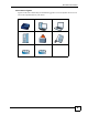
Document Conventions Icons Used in Figures Figures in this User’s Guide may use the following generic icons. The ZyXEL Device icon is not an exact representation of your device.
Safety Warnings Safety Warnings 1 For your safety, be sure to read and follow all warning notices and instructions. • Do NOT use this product near water, for example, in a wet basement or near a swimming pool. • Do NOT expose your device to dampness, dust or corrosive liquids. • Do NOT store things on the device. • Do NOT install, use, or service this device during a thunderstorm. There is a remote risk of electric shock from lightning. • Connect ONLY suitable accessories to the device.
Safety Warnings P-660R-T1 v3 User’s Guide 7
Safety Warnings 8 P-660R-T1 v3 User’s Guide
Contents Overview Contents Overview Introduction ............................................................................................................................ 25 Introducing the ZyXEL Device ................................................................................................... 27 Introducing the Web Configurator .............................................................................................. 31 Status ...............................................................
Contents Overview Troubleshooting and Product Specifications ................................................................... 153 Troubleshooting ....................................................................................................................... 155 Product Specifications ............................................................................................................. 159 Appendices and Index ...............................................................................
Table of Contents Table of Contents About This User's Guide .......................................................................................................... 3 Document Conventions............................................................................................................ 4 Safety Warnings........................................................................................................................ 6 Contents Overview .......................................................
Table of Contents Chapter 3 Device Information.................................................................................................................. 37 3.1 Overview .............................................................................................................................. 37 3.2 The Device Info Screen ....................................................................................................... 37 Chapter 4 System Logs................................................
Table of Contents 7.3.3 VPI and VCI ............................................................................................................... 64 7.3.4 IP Address Assignment .............................................................................................. 64 7.3.5 Always-On Connection (PPP) .................................................................................... 65 7.3.6 ATM QoS ....................................................................................................
Table of Contents 10.6 NAT Technical Reference .................................................................................................. 88 10.6.1 NAT Definitions ........................................................................................................ 88 10.6.2 What NAT Does ....................................................................................................... 89 10.6.3 How NAT Works ...................................................................................
Table of Contents 15.1 Overview ......................................................................................................................... 109 15.1.1 What You Can Do in the Filter Screens .................................................................. 109 15.1.2 What You Need to Know About Filtering ................................................................ 109 15.2 The IP/MAC Filter Screen ..............................................................................................
Table of Contents Chapter 21 Time Zone .............................................................................................................................. 139 21.1 Overview .......................................................................................................................... 139 21.2 The Time Zone Screen ................................................................................................... 139 Chapter 22 Firmware .................................................
Table of Contents Appendix B Pop-up Windows, JavaScripts and Java Permissions ...................................... 189 Appendix C IP Addresses and Subnetting ........................................................................... 197 Appendix D Services ............................................................................................................ 205 Appendix E Legal Information ..............................................................................................
Table of Contents 18 [Document Title]
List of Figures List of Figures Figure 1 ZyXEL Device’s Router Features ............................................................................................. 28 Figure 2 LEDs on the Top of the Device ................................................................................................. 29 Figure 3 Login Screen ............................................................................................................................ 32 Figure 4 Main Screen ...............................
List of Figures Figure 39 How NAT Works ..................................................................................................................... 90 Figure 40 QoS Example ......................................................................................................................... 91 Figure 41 Advanced Setup > QoS .......................................................................................................... 93 Figure 42 Advanced Setup > QoS > QoS Settings Summary .........
List of Figures Figure 82 Windows XP: Control Panel ................................................................................................. 171 Figure 83 Windows XP: Control Panel: Network Connections: Properties ........................................... 172 Figure 84 Windows XP: Local Area Connection Properties ................................................................. 172 Figure 85 Windows XP: Internet Protocol (TCP/IP) Properties ........................................................
List of Figures 22 [Document Title]
List of Tables List of Tables Table 1 LED Descriptions ...................................................................................................................... 29 Table 2 Navigation Panel Summary ...................................................................................................... 33 Table 3 Status > Device Information ...................................................................................................... 38 Table 4 Status > System Log .........................
List of Tables Table 39 Advanced > Dynamic DNS ................................................................................................... 130 Table 40 Access Management > CWMP ............................................................................................. 132 Table 41 Maintenance > Administraton ............................................................................................... 137 Table 42 Maintenance > Time Zone ...........................................................
P ART I Introduction Introducing the ZyXEL Device (27) Introducing the Web Configurator (31) 25
CHAPTER 1 Introducing the ZyXEL Device This chapter introduces the main applications and features of the ZyXEL Device. It also introduces the ways you can manage the ZyXEL Device. 1.1 Overview The P-660R-T1 v3 is an ADSL2+ router. By integrating DSL and NAT, you are provided with ease of installation and high-speed, shared Internet access. Models ending in “1”, for example P-660R-T1, denote a device that works over the analog telephone system, POTS (Plain Old Telephone Service).
Chapter 1 Introducing the ZyXEL Device 1.3 Good Habits for Managing the ZyXEL Device Do the following things regularly to make the ZyXEL Device more secure and to manage the ZyXEL Device more effectively. • Change the password. Use a password that’s not easy to guess and that consists of different types of characters, such as numbers and letters. • Write down the password and put it in a safe place. • Back up the configuration (and make sure you know how to restore it).
Chapter 1 Introducing the ZyXEL Device Use QoS to efficiently manage traffic on your network by giving priority to certain types of traffic and/or to particular computers. For example, you could make sure that the ZyXEL Device gives voice over Internet calls high priority, and/or limit bandwidth devoted to the boss’s excessive file downloading. 1.5 LEDs (Lights) The following graphic displays the labels of the LEDs.
Chapter 1 Introducing the ZyXEL Device 1.6 The RESET Button If you forget your password or cannot access the web configurator, you will need to use the RESET button at the back of the device to reload the factory-default configuration file. This means that you will lose all configurations that you had previously and the password will be reset to “1234”. 1.6.1 Using the Reset Button 1 Make sure the POWER LED is on (not blinking).
CHAPTER 2 Introducing the Web Configurator 2.1 Overview The web configurator is an HTML-based management interface that allows easy device setup and management via Internet browser. Use Internet Explorer 6.0 and later or Netscape Navigator 7.0 and later versions. The recommended screen resolution is 1024 by 768 pixels. In order to use the web configurator you need to allow: • Web browser pop-up windows from your device. Web pop-up blocking is enabled by default in Windows XP SP (Service Pack) 2.
Chapter 2 Introducing the Web Configurator Figure 3 Login Screen " For security reasons, the ZyXEL Device automatically logs you out if you do not use the web configurator for five minutes (default). If this happens, log in again. 2.
Chapter 2 Introducing the Web Configurator 2.2.1 Navigation Panel Use the menu items on the navigation panel to open screens to configure ZyXEL Device features. The following tables describe each menu item. Table 2 Navigation Panel Summary LINK TAB FUNCTION Status Device Info This screen shows the ZyXEL Device’s general device and network status information. System Log Use this screen to display your device’s logs. Statistics Use this screen to display the statistics of the ZyXEL Device.
Chapter 2 Introducing the Web Configurator Table 2 Navigation Panel Summary LINK TAB FUNCTION URL Filter Use this screen to allow or deny traffic from certain types of applications. SNMP Use this screen to configure your ZyXEL Device’s settings for Simple Network Management Protocol management. UPnP Use this screen to turn UPnP on or off. DDNS This screen allows you to use a static hostname alias for a dynamic IP address. CWMP Use this screen to have a management server manage the ZyXEL Device.
P ART II Status Device Information (37) System Logs (39) Traffic Statistics (41) 35
CHAPTER 3 Device Information 3.1 Overview Use the Device Info screen to look at the current status of the device, system resources, and interfaces (LAN and WAN). 3.2 The Device Info Screen Use this screen to view the status of the ZyXEL Device. Click Status > Device Info to open the following screen.
Chapter 3 Device Information The following table describes the fields in this screen. Table 3 Status > Device Information LABEL DESCRIPTION Device Information Firmware Version This is the current version of the firmware inside the device. It also shows the date the firmware version was created. MAC Address This is the MAC (Media Access Control) or Ethernet address unique to your ZyXEL Device. LAN IP Address This is the current IP address of the ZyXEL Device in the LAN.
CHAPTER 4 System Logs 4.1 Overview This chapter contains information about viewing the ZyXEL Device’s logs. A log is a message about an event that occurred on your ZyXEL Device. For example, when someone logs in to the ZyXEL Device. 4.2 The System Log Screen Use this screen to see the logs for your ZyXEL Device. Click Status > System Log to open the following screen. Figure 6 Status > System Log The following table describes the fields in this screen.
Chapter 4 System Logs Table 4 Status > System Log 40 LABEL DESCRIPTION CLEAR LOG Click this to delete all the logs. SAVE LOG Click this to save the logs in a text file.
CHAPTER 5 Traffic Statistics 5.1 Overview This chapter contains information about viewing traffic statistics of your ZyXEL Device. 5.2 The Statistics Screen Use this screen to check the traffic statistics of your ZyXEL Device. Click Status > Statistics to open the following screen. The screen varies depending on what type of port you selected in the Interface field. The following screen displays traffic statistics for the Ethernet port.
Chapter 5 Traffic Statistics Table 5 Status > Statistics (Ethernet) (continued) LABEL DESCRIPTION Receive Multicast Frames This field displays the number of good multicast frames received. Receive total Bytes This field displays the number of bytes received on this port. Receive CRC errors This field displays the number of frames received with Cyclic Redundant Check (CRC) errors.
P ART III Quick Start Wizard Quick Start Wizard (45) 43
CHAPTER 6 Quick Start Wizard 6.1 Overview This chapter provides information on the Quick Start Wizard screens. Use the wizard screens to configure your system for Internet access with the information given to you by your ISP. " See the advanced menu chapters for background information on these fields. 6.2 Quick Start Wizard 1 After you enter the password to access the web configurator, click Quick Start > Quick Start from the navigation panel to go to the wizard screens.
Chapter 6 Quick Start Wizard 2 Click RUN WIZARD to configure the system for Internet access. Figure 10 Run Wizard 3 The following screen summarizes the steps required to configure an Internet connection. Click NEXT to begin the setup. Figure 11 Wizard Summary 4 Enter a new password for accessing the web configurator or enter your old one if you don’t want to change it. Type the new or old password in both fields and click NEXT.
Chapter 6 Quick Start Wizard 5 Select the time zone for your location and click NEXT. Figure 13 Time Zone 6 Select the connection type supported by your ISP and click NEXT. Figure 14 ISP Connection Type 7 The next wizard screen varies depending on what connection type you use. Configure the fields and click NEXT to continue.
Chapter 6 Quick Start Wizard The following table describes the fields in this screen. Table 7 ISP Connection: Dynamic IP LABEL DESCRIPTION VPI Enter the VPI (Virtual Path Identifier) assigned to you. This field may already be configured. VPI defines a virtual circuit. Refer to the appendix for more information. VCI Enter the VCI (Virtual Channel Identifier) assigned to you. This field may already be configured. VCI defines a virtual circuit. Refer to the appendix for more information.
Chapter 6 Quick Start Wizard Figure 17 ISP Connection: PPPoE/PPPoA The following table describes the fields in this screen. Table 9 ISP Connection: PPPoE/PPPoA LABEL DESCRIPTION Username Enter the username exactly as your ISP assigned. If assigned a name in the form user@domain where domain identifies a service name, then enter both components exactly as given. Password Enter the password associated with the above username. VPI Enter the VPI assigned to you. This field may already be configured.
Chapter 6 Quick Start Wizard The following table describes the fields in this screen. Table 10 ISP Connection: Bridge Mode LABEL DESCRIPTION VPI Enter the VPI assigned to you. This field may already be configured. VPI defines a virtual circuit. Refer to the appendix for more information. VCI Enter the VCI assigned to you. This field may already be configured. VCI defines a virtual circuit. Refer to the appendix for more information.
P ART IV Interface Setup Internet Setup (53) LAN Setup (67) 51
CHAPTER 7 Internet Setup 7.1 Overview This chapter describes how to configure Wide Area Network (WAN) settings from the Internet screens. Use these screens to configure your ZyXEL Device for Internet access. A WAN connection is an outside connection to another network or the Internet. It connects your private networks (such as a Local Area Network (LAN) and other networks, so that a computer in one location can communicate with computers in other locations. Figure 20 LAN and WAN LAN WAN 7.1.
Chapter 7 Internet Setup ADSL Terms A Permanent Virtual Circuit (PVC) is the connection for your device to the ISP. You need a Virtual Path Identifier (VPI) and a Virtual Channel Identifier (VCI) to identify a PVC. Multiplexing is a way of carrying protocols on a PVC. Your ISP should supply you with all this information. WAN IP Address The WAN IP address is an IP address for the ZyXEL Device, which makes it accessible from an outside network.
Chapter 7 Internet Setup 7.2 The Internet Screen Use this screen to change your ZyXEL Device’s WAN settings. Click Interface Setup > Internet. The screen differs by the encapsulation you select. Figure 21 Interface Setup > Internet The following table describes the labels in this screen. Table 11 Interface Setup > Internet LABEL DESCRIPTION ATM VC Virtual Circuit PVCs Summary Select the PVC you want to configure from the drop-down list box.
Chapter 7 Internet Setup Table 11 Interface Setup > Internet (continued) LABEL DESCRIPTION ATM QoS Select CBR (Continuous Bit Rate) to specify fixed (always-on) bandwidth for voice or data traffic. Select UBR (Unspecified Bit Rate) for applications that are non-time sensitive, such as e-mail. Select rtVBR (real-time Variable Bit Rate) for applications with bursty connections that require closely controlled delay and delay variation.
Chapter 7 Internet Setup The following table describes the labels in this screen. Table 12 Interface Setup > Internet (Dynamic IP) LABEL DESCRIPTION Encapsulation Select the method of multiplexing used by your ISP from the drop-down list box. Available options are: 1483 Bridged IP LLC, 1483 Bridged IP VC-Mux, 1483 Routed IP LLC(IPoA) and 1483 Routed IP VC-Mux. Bridge Interface This field is only available when you select 1483 Bridged IP LLC or 1483 Bridged IP VC-Mux in the Encapsulation field.
Chapter 7 Internet Setup 7.2.2 Static IP Address In the Interface Setup > Internet screen, select Static IP Address from the ISP field to display the following screen. Figure 23 Interface Setup > Internet (Static IP) The following table describes the labels in this screen. Table 13 Interface Setup > Internet (Static IP) 58 LABEL DESCRIPTION Encapsulation Select the method of multiplexing used by your ISP from the drop-down list box.
Chapter 7 Internet Setup Table 13 Interface Setup > Internet (Static IP) (continued) LABEL DESCRIPTION Dynamic Route RIP (Routing Information Protocol) allows a router to exchange routing information with other routers. Select the RIP version from RIP1, RIP2-B and RIP2-M. Direction Use this field to control how much routing information the ZyXEL Device sends and receives on the subnet. Select the RIP direction from None, Both, IN Only and OUT Only.
Chapter 7 Internet Setup 7.2.3 PPPoA/PPPoE In the Interface Setup > Internet screen, select PPPoA/PPPoE from the ISP field to display the following screen. Figure 24 Interface Setup > Internet (PPPoA/PPPoE) The following table describes the labels in this screen. Table 14 Interface Setup > Internet (PPPoA/PPPoE) LABEL DESCRIPTION PPPoE/PPPoA 60 Servicename Type the name of your service in this field. Username Enter the username exactly as your ISP assigned.
Chapter 7 Internet Setup Table 14 Interface Setup > Internet (PPPoA/PPPoE) (continued) LABEL DESCRIPTION Bridge Interface This field is only available when you select PPPoE LLC or PPPoE VC-Mux in the Encapsulation field. Use this field to enable or disable the bridge mode. Activate the bridge mode when your ISP provides you with more than one IP address and you want the connected computers to get individual IP address from ISP’s DHCP server directly.
Chapter 7 Internet Setup 7.2.4 Bridge Mode In the Interface Setup > Internet screen, select Bridge Mode from the ISP field to display the following screen. Figure 25 Interface Setup > Internet (Bridge) The following table describes the labels in this screen. Table 15 Interface Setup > Internet (Bridge) LABEL DESCRIPTION Encapsulation Select the method of multiplexing used by your ISP from the drop-down list box. Available options are: 1483 Bridged IP LLC and 1483 Bridged IP VC-Mux. 7.2.
Chapter 7 Internet Setup Table 16 Interface Setup > PVCs Summary (continued) LABEL DESCRIPTION ENCAP This field displays the type of encapsulation. Mux This field displays the multiplexing method. IP Address This field displays the type of IP address. Status This field displays the connection status of the PVC. 7.3 WAN Technical Reference This section provides some technical background information about the topics covered in this chapter. 7.3.
Chapter 7 Internet Setup RFC 1483 RFC 1483 describes two methods for Multiprotocol Encapsulation over ATM Adaptation Layer 5 (AAL5). The first method allows multiplexing of multiple protocols over a single ATM virtual circuit (LLC-based multiplexing) and the second method assumes that each protocol is carried over a separate ATM virtual circuit (VC-based multiplexing). Please refer to RFC 1483 for more detailed information. 7.3.
Chapter 7 Internet Setup 7.3.5 Always-On Connection (PPP) An always-on connection is a dial-up line where the connection is always up regardless of traffic demand. The ZyXEL Device does two things when you specify an always-on connection. The first is that idle timeout is disabled. The second is that the ZyXEL Device will try to bring up the connection when turned on and whenever the connection is down. An always-on connection can be very expensive for obvious reasons.
Chapter 7 Internet Setup 7.3.7 ATM Traffic Classes These are the basic ATM traffic classes defined by the ATM Forum Traffic Management 4.0 Specification. Constant Bit Rate (CBR) Constant Bit Rate (CBR) provides fixed bandwidth that is always available even if no data is being sent. CBR traffic is generally time-sensitive (doesn't tolerate delay). CBR is used for connections that continuously require a specific amount of bandwidth. A PCR is specified and if traffic exceeds this rate, cells may be dropped.
CHAPTER 8 LAN Setup 8.1 Overview A Local Area Network (LAN) is a shared communication system to which many networking devices are connected. It is usually located in one area such as a building or floor of a building. Use the LAN screen to help you configure a LAN DHCP server and manage IP addresses. LAN DSL 8.1.1 What You Can Do in the LAN Screens • Use the LAN screen (Section 8.2 on page 68) to set the LAN IP address and subnet mask of your ZyXEL device.
Chapter 8 LAN Setup DHCP A DHCP (Dynamic Host Configuration Protocol) server can assign your ZyXEL Device an IP address, subnet mask, DNS and other routing information when it's turned on. RIP RIP (Routing Information Protocol) allows a router to exchange routing information with other routers. Multicast Traditionally, IP packets are transmitted in one of either two ways - Unicast (1 sender - 1 recipient) or Broadcast (1 sender - everybody on the network).
Chapter 8 LAN Setup Figure 28 Interface Setup > LAN The following table describes the fields in this screen. Table 17 Interface Setup > LAN LABEL DESCRIPTION Router Local IP IP Address Enter the LAN IP address you want to assign to your ZyXEL Device in dotted decimal notation, for example, 192.168.1.1 (factory default). IP Subnet Mask Type the subnet mask of your network in dotted decimal notation, for example 255.255.255.0 (factory default).
Chapter 8 LAN Setup Table 17 Interface Setup > LAN LABEL Current Pool Summary DESCRIPTION Click this to display a summary table for the IP address pool. See Section 8.2.1 on page 70 for more details. The ZyXEL Device is pre-configured with a pool of IP addresses for the DHCP clients (DHCP Pool). See the product specifications in the appendices. Do not assign static IP addresses from the DHCP pool to your LAN computers. IP Pool Count This field specifies the size, or count of the IP address pool.
Chapter 8 LAN Setup The following table describes the labels in this screen. Table 18 Interface Setup > LAN > DHCP IP Pool Summary LABEL DESCRIPTION Host Name This field displays the name of a computer that receives an IP address from the ZyXEL Device. IP Address This field displays the IP address of a computer that receives an IP address from the ZyXEL Device. MAC Address This field displays the MAC address of a computer that receives an IP address from the ZyXEL Device. 8.
Chapter 8 LAN Setup 8.3.3 DNS Server Addresses DNS (Domain Name System) maps a domain name to its corresponding IP address and vice versa. The DNS server is extremely important because without it, you must know the IP address of a computer before you can access it. The DNS server addresses you enter when you set up DHCP are passed to the client machines along with the assigned IP address and subnet mask. There are two ways that an ISP disseminates the DNS server addresses.
Chapter 8 LAN Setup Once you have decided on the network number, pick an IP address that is easy to remember, for instance, 192.168.1.1, for your ZyXEL Device, but make sure that no other device on your network is using that IP address. The subnet mask specifies the network number portion of an IP address. Your ZyXEL Device will compute the subnet mask automatically based on the IP address that you entered.
Chapter 8 LAN Setup The Version field controls the format and the broadcasting method of the RIP packets that the ZyXEL Device sends (it recognizes both formats when receiving). RIP-1 is universally supported; but RIP-2 carries more information. RIP-1 is probably adequate for most networks, unless you have an unusual network topology. Both RIP-2B and RIP-2M sends the routing data in RIP-2 format; the difference being that RIP-2B uses subnet broadcasting while RIP-2M uses multicasting. 8.3.
P ART V Advanced Setup Static Route (77) Network Address Translation (NAT) (81) Quality of Service (QoS) (91) ADSL (99) Firewall (101) 75
CHAPTER 9 Static Route 9.1 Overview The ZyXEL Device usually uses the default gateway to route outbound traffic from computers on the LAN to the Internet. To have the ZyXEL Device send data to devices not reachable through the default gateway, use static routes. For example, the next figure shows a computer (A) connected to the ZyXEL Device’s LAN interface. The ZyXEL Device routes most traffic from A to the Internet through the ZyXEL Device’s default gateway (R1).
Chapter 9 Static Route 9.2 The Routing Table List Screen Use this screen to view the static route rules. Click Advanced Setup > Routing to display the following screen. Figure 32 Advanced Setup > Routing Table List The following table describes the labels in this screen. Table 19 Advanced Setup > Routing Table List LABEL DESCRIPTION # This is the number of an individual static route. Dest IP This parameter specifies the IP network address of the final destination.
Chapter 9 Static Route The following table describes the labels in this screen. Table 20 Advanced > Static Route: Edit LABEL DESCRIPTION Destination IP Address This parameter specifies the IP network address of the final destination. Routing is always based on network number. If you need to specify a route to a single host, use a subnet mask of 255.255.255.255 in the subnet mask field to force the network number to be identical to the host ID. IP Subnet Mask Enter the IP subnet mask in this field.
Chapter 9 Static Route 80 P-660R-T1 v3 User’s Guide
CHAPTER 10 Network Address Translation (NAT) 10.1 Overview This chapter discusses how to configure NAT on the ZyXEL Device. NAT (Network Address Translation - NAT, RFC 1631) is the translation of the IP address of a host in a packet, for example, the source address of an outgoing packet, used within one network to a different IP address known within another network. 10.1.1 What You Can Do in the NAT Screens • Use the NAT screen (Section 10.2 on page 82) to configure the NAT settings.
Chapter 10 Network Address Translation (NAT) NAT In the simplest form, NAT changes the source IP address in a packet received from a subscriber (the inside local address) to another (the inside global address) before forwarding the packet to the WAN side. When the response comes back, NAT translates the destination address (the inside global address) back to the inside local address before forwarding it to the original inside host.
Chapter 10 Network Address Translation (NAT) Table 21 Network > NAT > General (continued) LABEL DESCRIPTION Number of IPs Select Single if you have just one public WAN IP address for your ZyXEL Device. Select Multiple if you have multiple public WAN IP addresses for your ZyXEL Device. DMZ Click this to configure the DMZ settings. See Section 10.3 on page 83 for more details. Virtual Server Click this to configure port forwarding rules for your ZyXEL Device. See Section 10.
Chapter 10 Network Address Translation (NAT) 10.4 The Virtual Server Screen LAN computers usually have DHCP-assigned private IP address that cannot be accessed directly from the WAN. Use this screen to allow the ZyXEL Device to forward traffic to the servers on the LAN. You may enter a single port number or a range of port numbers to be forwarded, and the local IP address of the desired server. The port number identifies a service; for example, web service is on port 80 and FTP on port 21.
Chapter 10 Network Address Translation (NAT) 10.4.2 Configuring the Virtual Server Screen Click Advanced Setup > NAT > Virtual Server to open the following screen. See Appendix D on page 205 for port numbers commonly used for particular services. Figure 37 Advanced Setup > NAT > Virtual Server The following table describes the fields in this screen. Table 24 Advanced Setup > NAT > Virtual Server LABEL DESCRIPTION Virtual Server Virtual Server for This is the PVC that this virtual server will use.
Chapter 10 Network Address Translation (NAT) Table 24 Advanced Setup > NAT > Virtual Server LABEL DESCRIPTION Start Port Number Enter a port number in this field. To forward only one port, enter the port number again in the End Port Number field. To forward a series of ports, enter the start port number here and the end port number in the End Port Number field. End Port Number Enter a port number in this field.
Chapter 10 Network Address Translation (NAT) Use this screen to change your ZyXEL Device’s address mapping settings. Click Advanced Setup > NAT > IP Address Mapping to open the following screen. Figure 38 Advanced Setup > NAT > IP Address Mapping The following table describes the fields in this screen. Table 25 Network > NAT > Address Mapping LABEL DESCRIPTION IP Address Mapping Address Mapping Rule The rules configured in this screen apply to this PVC.
Chapter 10 Network Address Translation (NAT) Table 25 Network > NAT > Address Mapping (continued) LABEL DESCRIPTION Address Mapping List Rule This is the rule’s index number. Type 1-1: One-to-One mode maps one local IP address to one public IP address. Note that port numbers do not change for the One-to-One NAT mapping type. M-1: Many-to-One mode maps multiple local IP addresses to one public IP address. This is equivalent to the Single IP feature that previous ZyXEL routers supported only.
Chapter 10 Network Address Translation (NAT) Note that inside/outside refers to the location of a host, while public/local refers to the IP address of a host used in a packet. Thus, an inside local address is the IP address of an inside host in a packet when the packet is still in the local network, while an inside public address is the IP address of the same inside host when the packet is on the WAN side. The following table summarizes this information.
Chapter 10 Network Address Translation (NAT) Figure 39 How NAT Works NAT Table LAN Inside Local IP Address 192.168.1.10 192.168.1.11 192.168.1.12 192.168.1.13 192.168.1.13 192.168.1.12 SA SA 192.168.1.10 1 Inside Local Address 192.168.1.11 90 Inside Public IP Address 1 2 3 4 WAN Inside Public Address 192.168.1.
CHAPTER 11 Quality of Service (QoS) 11.1 Overview Use the QoS screen to set up your ZyXEL Device to use QoS for traffic management. Quality of Service (QoS) refers to both a network’s ability to deliver data with minimum delay, and the networking methods used to control bandwidth. QoS allows the ZyXEL Device to group and prioritize application traffic and fine-tune network performance. Without QoS, all traffic data are equally likely to be dropped when the network is congested.
Chapter 11 Quality of Service (QoS) 11.1.1 What You Can Do in the QoS Screens • Use the QoS screen (Section 11.2 on page 93) to configure QoS settings on the ZyXEL Device. • Use the QoS Settings Summary screen (Section 11.2.1 on page 95) to check the summary of QoS rules and actions you configured for the ZyXEL Device. 11.1.2 What You Need to Know About QoS 802.1p QoS is used to prioritize source-to-destination traffic flows. All packets in the same flow are given the same priority. 802.
Chapter 11 Quality of Service (QoS) 11.2 The QoS Screen Use this screen to enable or disable QoS and have the ZyXEL Device assign priority levels to traffic according to the port range, IEEE 802.1p priority level and/or IP precedence. Click Advanced Setup > QoS to open the screen as shown next. Figure 41 Advanced Setup > QoS The following table describes the labels in this screen.
Chapter 11 Quality of Service (QoS) Table 27 Advanced Setup > QoS LABEL DESCRIPTION Rule Index Select the rule’s index number from the drop-down list box. Active Use this field to enable or disable the rule. Application Select an application from the drop-down list box. The Destination Port Range and Protocol ID fields may change depending on the type of applications you choose. Physical Ports Select Enet1 to apply the rule to the Ethernet port. Destination MAC Type a destination MAC address here.
Chapter 11 Quality of Service (QoS) Table 27 Advanced Setup > QoS LABEL DESCRIPTION Queue # Specify a Low, Medium, High or Highest queue tag to matched traffic. Traffic assigned to a higher queue gets through faster while traffic in lower queues is dropped when there is network congestion. ADD Click this to add the rule. DELETE Click this to remove the rule. CANCEL Click this to restore previously saved settings. 11.2.
Chapter 11 Quality of Service (QoS) Table 28 Advanced Setup > QoS > QoS Settings Summary (continued) LABEL DESCRIPTION IPP/TOS (DSCP) Remarking The ZyXEL Device re-assigns the priority values specified in this field to matched traffic. 802.1p Remarking The ZyXEL Device re-assigns the priority levels specified in this field to matched traffic. Queue # The ZyXEL Device assigns the queue level specified in this field to matched traffic. 11.
Chapter 11 Quality of Service (QoS) 11.3.3 Automatic Priority Queue Assignment If you enable QoS on the ZyXEL Device, the ZyXEL Device can automatically base on the IEEE 802.1p priority level, IP precedence and/or packet length to assign priority to traffic which does not match a class. The following table shows you the internal layer-2 and layer-3 QoS mapping on the ZyXEL Device.
Chapter 11 Quality of Service (QoS) 98 P-660R-T1 v3 User’s Guide
CHAPTER 12 ADSL 12.1 Overview This chapter contains information about configuring the ADSL settings for your ZyXEL Device. 12.2 The ADSL Screen Use this screen to select the ADSL mode and type for your ZyXEL Device. Click Advanced Setup > ADSL to open the following screen. Figure 43 Advanced Setup > ADSL The following table describes the labels in this screen. Table 31 Advanced Setup > ADSL LABEL DESCRIPTION ADSL Mode Select the mode supported by your ISP.
Chapter 12 ADSL 100 P-660R-T1 v3 User’s Guide
CHAPTER 13 Firewall 13.1 Overview This chapter shows you how to enable the ZyXEL Device firewall. Use the firewall to protect your ZyXEL Device and network from attacks by hackers on the Internet and control access to it. By default the firewall: • allows traffic that originates from your LAN computers to go to all other networks. • blocks traffic that originates on other networks from going to the LAN. • blocks SYN and port scanner attacks.
Chapter 13 Firewall LAND Attack In a LAND attack, hackers flood SYN packets into the network with a spoofed source IP address of the target system. This makes it appear as if the host computer sent the packets to itself, making the system unavailable while the target system tries to respond to itself. Ping of Death Ping of Death uses a "ping" utility to create and send an IP packet that exceeds the maximum 65,536 bytes of data allowed by the IP specification.
P ART VI Access Management Access Control (105) Filters (109) SNMP (115) Universal Plug-and-Play (UPnP) (117) Dynamic DNS Setup (129) CWMP (131) 103
CHAPTER 14 Access Control 14.1 Access Control Overview Access Control allows you to determine which application can access which ZyXEL Device interface from which computers. The following figure shows access to the ZyXEL Device from the WAN being limited to HTTP (web) and Telnet only. Figure 45 Access Control LAN WAN HTTP Telnet 14.1.1 The Access Control Setup Screen Use this screen to configure from where and how users may access the ZyXEL Device. 14.1.
Chapter 14 Access Control 14.1.3 System Timeout There is a default system management idle timeout of five minutes (three hundred seconds). The ZyXEL Device automatically logs you out if the management session remains idle for longer than this timeout period. The management session does not time out when a statistics screen is polling. 14.1.4 Configuring the Access Control Setup Screen Click Access Management > ACL to open the following screen.
Chapter 14 Access Control Table 33 Access Management > ACL (continued) LABEL DESCRIPTION Interface Select the port through which you can access the device. Select Both for access via either port. If you configure 0.0.0.0 ~ 0.0.0.0 Secure IP Address, ALL services and WAN interface, you will not be able to access the device at all from the LAN unless you configure another rule for LAN access. Access Control Listing The summary table displays the configured parameters for the selected rule.
Chapter 14 Access Control 108 P-660R-T1 v3 User’s Guide
CHAPTER 15 Filters 15.1 Overview This chapter introduces three types of filters supported by the ZyXEL Device. You can configure rules to restrict traffic by IP addresses, MAC addresses, application types and/or URLs. 15.1.1 What You Can Do in the Filter Screens • Use the IP/MAC Filter screen (Section 15.2 on page 110) to create IP/MAC filter rules. • Use the Application Filter screen (Section 15.3 on page 112) to allow or deny traffic from certain types of applications.
Chapter 15 Filters 15.2 The IP/MAC Filter Screen Use this screen to create and apply IP/MAC filters. Click Access Management > Filter and select IP/MAC Filter in the Filter Type Selection field. The screen appears as shown. Figure 47 Access Management > Filter (IP/MAC) The following table describes the labels in this screen. Table 34 Access Management > Filter (IP/MAC) LABEL DESCRIPTION Filter Type Filter Type Selection Select the filter type from the drop-down list box.
Chapter 15 Filters Table 34 Access Management > Filter (IP/MAC) (continued) LABEL DESCRIPTION IP/MAC Filter Rule Index Select the index number of the filter rule. Rule Type Select IP or MAC type to configure the rule. Use the IP Filter to block traffic by IP addresses. Use the MAC Filter to block traffic by MAC address. Active Use this field to enable or disable the rule. Source IP Address Enter the source IP address of the packets you wish to filter. This field is ignored if it is 0.0.0.0.
Chapter 15 Filters 15.3 The Application Filter Screen Use this screen to allow or deny traffic for certain types of applications. The application filter provides a convenient way to manage the use of various applications on the network. Click Access Management > Filter and select Application Filter in the Filter Type Selection field. The screen appears as shown. Figure 48 Access Management > Filter (Application) The following table describes the labels in this screen.
Chapter 15 Filters 15.4 The URL Filter Screen Use this screen to block websites by URL. Click Access Management > Filter and select URL Filter in the Filter Type Selection field.. The screen appears as shown. Figure 49 Access Management > Filter (URL) The following table describes the labels in this screen. Table 36 Access Management > Filter (URL) LABEL DESCRIPTION URL Filter Editing Active Use this field to enable or disable the URL filter. URL Index Select the index number of the filter.
Chapter 15 Filters 114 P-660R-T1 v3 User’s Guide
CHAPTER 16 SNMP 16.1 Overview Simple Network Management Protocol (SNMP) is a protocol used for exchanging management information between network devices. SNMP is a member of the TCP/IP protocol suite. Your ZyXEL Device supports SNMP agent functionality, which allows a manager station to manage and monitor the ZyXEL Device through the network. The ZyXEL Device supports SNMP version one (SNMPv1) and version two (SNMPv2). The next figure illustrates an SNMP management operation.
Chapter 16 SNMP SNMP itself is a simple request/response protocol based on the manager/agent model. The manager issues a request and the agent returns responses using the following protocol operations: • Get - Allows the manager to retrieve an object variable from the agent. • Set - Allows the manager to set values for object variables within an agent. 16.1.1 Supported MIBs The ZyXEL Device supports MIB II, which is defined in RFC-1213 and RFC-1215.
CHAPTER 17 Universal Plug-and-Play (UPnP) 17.1 Overview Universal Plug and Play (UPnP) is a distributed, open networking standard that uses TCP/IP for simple peer-to-peer network connectivity between devices. A UPnP device can dynamically join a network, obtain an IP address, convey its capabilities and learn about other devices on the network. In turn, a device can leave a network smoothly and automatically when it is no longer in use. 17.1.
Chapter 17 Universal Plug-and-Play (UPnP) When a UPnP device joins a network, it announces its presence with a multicast message. For security reasons, the ZyXEL Device allows multicast messages on the LAN only. All UPnP-enabled devices may communicate freely with each other without additional configuration. Disable UPnP if this is not your intention. UPnP and ZyXEL ZyXEL has achieved UPnP certification from the Universal Plug and Play Forum UPnP™ Implementers Corp. (UIC).
Chapter 17 Universal Plug-and-Play (UPnP) 17.3 Installing UPnP in Windows Example This section shows how to install UPnP in Windows Me and Windows XP. Installing UPnP in Windows Me Follow the steps below to install the UPnP in Windows Me. 1 Click Start and Control Panel. Double-click Add/Remove Programs. 2 Click on the Windows Setup tab and select Communication in the Components selection box. Click Details.
Chapter 17 Universal Plug-and-Play (UPnP) 3 In the Communications window, select the Universal Plug and Play check box in the Components selection box. Figure 54 Add/Remove Programs: Windows Setup: Communication: Components 4 Click OK to go back to the Add/Remove Programs Properties window and click Next. 5 Restart the computer when prompted. Installing UPnP in Windows XP Follow the steps below to install the UPnP in Windows XP. 1 Click Start and Control Panel. 2 Double-click Network Connections.
Chapter 17 Universal Plug-and-Play (UPnP) 4 The Windows Optional Networking Components Wizard window displays. Select Networking Service in the Components selection box and click Details. Figure 56 Windows Optional Networking Components Wizard 5 In the Networking Services window, select the Universal Plug and Play check box.
Chapter 17 Universal Plug-and-Play (UPnP) 6 Click OK to go back to the Windows Optional Networking Component Wizard window and click Next. 17.4 Using UPnP in Windows XP Example This section shows you how to use the UPnP feature in Windows XP. You must already have UPnP installed in Windows XP and UPnP activated on the ZyXEL Device. Make sure the computer is connected to a LAN port of the ZyXEL Device. Turn on your computer and the ZyXEL Device.
Chapter 17 Universal Plug-and-Play (UPnP) 3 In the Internet Connection Properties window, click Settings to see the port mappings there were automatically created.
Chapter 17 Universal Plug-and-Play (UPnP) 4 You may edit or delete the port mappings or click Add to manually add port mappings. Figure 60 Internet Connection Properties: Advanced Settings Figure 61 Internet Connection Properties: Advanced Settings: Add 5 When the UPnP-enabled device is disconnected from your computer, all port mappings will be deleted automatically.
Chapter 17 Universal Plug-and-Play (UPnP) 6 Select Show icon in notification area when connected option and click OK. An icon displays in the system tray. Figure 62 System Tray Icon 7 Double-click on the icon to display your current Internet connection status. Figure 63 Internet Connection Status Web Configurator Easy Access With UPnP, you can access the web-based configurator on the ZyXEL Device without finding out the IP address of the ZyXEL Device first.
Chapter 17 Universal Plug-and-Play (UPnP) Figure 64 Network Connections 4 An icon with the description for each UPnP-enabled device displays under Local Network.
Chapter 17 Universal Plug-and-Play (UPnP) 5 Right-click on the icon for your ZyXEL Device and select Invoke. The web configurator login screen displays. Figure 65 Network Connections: My Network Places 6 Right-click on the icon for your ZyXEL Device and select Properties. A properties window displays with basic information about the ZyXEL Device.
Chapter 17 Universal Plug-and-Play (UPnP) 128 P-660R-T1 v3 User’s Guide
CHAPTER 18 Dynamic DNS Setup 18.1 Overview Dynamic DNS allows you to update your current dynamic IP address with one or many dynamic DNS services so that anyone can contact you (in NetMeeting, CU-SeeMe, etc.). You can also access your FTP server or Web site on your own computer using a domain name (for instance myhost.dhs.org, where myhost is a name of your choice) that will never change instead of using an IP address that changes each time you reconnect.
Chapter 18 Dynamic DNS Setup 18.2 The Dynamic DNS Screen Use this screen to change your ZyXEL Device’s DDNS. Click Access Management > DDNS. The screen appears as shown. Figure 67 Access Management > DDNS The following table describes the fields in this screen. Table 39 Advanced > Dynamic DNS LABEL DESCRIPTION Dynamic DNS Use this field to enable or disable dynamic DNS. Service Provider This is the name of your Dynamic DNS service provider.
CHAPTER 19 CWMP 19.1 Overview The ZyXEL Device supports TR-069 Amendment 1 (CPE WAN Management Protocol Release 2.0) and TR-069 Amendment 2 (CPE WAN Management Protocol v1.1, Release 3.0). TR-069 is a protocol that defines how your ZyXEL Device (ZD) can be managed via a management server (MS) such as ZyXEL’s Vantage Access.
Chapter 19 CWMP 19.2 The CWMP Setup Screen Use this screen to configure your ZyXEL Device to be managed by a management server. Click Access Management > CWMP to display the following screen. Figure 69 Access Management > CWMP The following table describes the fields in this screen.
Chapter 19 CWMP Table 40 Access Management > CWMP (continued) LINK DESCRIPTION Port The default port for access to the ZyXEL Device from the management server is the HTTP port, port 80. If you change it, make sure it does not conflict with another port on your network and it is recommended to use a port number above 1024 (not a commonly used port). The management server should use this port to connect to the ZyXEL Device.
Chapter 19 CWMP 134 P-660R-T1 v3 User’s Guide
P ART VII Maintenance Administrator Settings (137) Time Zone (139) Firmware (141) System Restart (149) Diagnostic (151) 135
CHAPTER 20 Administrator Settings 20.1 Overview This chapter shows you how to change the system password. 20.2 The Administrator Screen Use this screen to set a new password for your ZyXEL Device. Click Maintenance > Administraton to open the following screen. Figure 70 Maintenance > Administraton The following table describes the labels in this screen. Table 41 Maintenance > Administraton LABEL DESCRIPTION New Password Type your new password (up to 30 characters).
Chapter 20 Administrator Settings 138 P-660R-T1 v3 User’s Guide
CHAPTER 21 Time Zone 21.1 Overview This chapter contains information about configuring your ZyXEL Device’s time settings. 21.2 The Time Zone Screen Use this screen to configure the ZyXEL Device’s time based on your local time zone. To change your ZyXEL Device’s time and date, click Maintenance > Time Zone. The screen appears as shown. Figure 71 Maintenance > Time Zone The following table describes the fields in this screen.
Chapter 21 Time Zone Table 42 Maintenance > Time Zone (continued) 140 LABEL DESCRIPTION Daylight Saving Daylight saving is a period from late spring to early fall when many countries set their clocks ahead of normal local time by one hour to give more daytime light in the evening. Select Enabled if you use Daylight Saving Time. NTP Server Address Enter the IP address or URL (up to 20 extended ASCII characters in length) of your time server.
CHAPTER 22 Firmware 22.1 Overview This chapter explains how to upload new firmware and manage configuration files. Use the instructions in this chapter to change the device’s configuration file or upgrade its firmware. After you configure your device, you can backup the configuration file to a computer. That way if you later misconfigure the device, you can upload the backed up configuration file to return to your previous settings.
Chapter 22 Firmware If your (T)FTP client does not allow you to have a destination filename different than the source, you will need to rename them as the ZyXEL Device only recognizes “rom-0” and “ras”. Be sure you keep unaltered copies of both files for later use. The following table is a summary.
Chapter 22 Firmware 1 Do not interrupt the file transfer process as this may PERMANENTLY DAMAGE your device. When the Restore Configuration process is complete, the device automatically restarts. Restore Using FTP Session Example Figure 72 Restore Using FTP Session Example ftp> put config.rom rom-0 200 Port command okay 150 Opening data connection for STOR rom-0 226 File received OK 221 Goodbye for writing flash ftp: 16384 bytes sent in 0.06Seconds 273.07Kbytes/sec. ftp>quit Refer to Section 22.1.
Chapter 22 Firmware 7 Enter “quit” to exit the ftp prompt. FTP Session Example of Firmware File Upload Figure 73 FTP Session Example of Firmware File Upload 331 Enter PASS command Password: 230 Logged in ftp> bin 200 Type I OK ftp> put firmware.bin ras 200 Port command okay 150 Opening data connection for STOR ras 226 File received OK ftp: 1103936 bytes sent in 1.10Seconds 297.89Kbytes/sec. ftp> quit More commands (found in GUI-based FTP clients) are listed in this chapter. Refer to Section 22.1.
Chapter 22 Firmware Where “i” specifies binary image transfer mode (use this mode when transferring binary files), “host” is the device’s IP address, “put” transfers the file source on the computer (firmware.bin – name of the firmware on the computer) to the file destination on the remote host (ras - name of the firmware on the device). Commands that you may see in GUI-based TFTP clients are listed earlier in this chapter.
Chapter 22 Firmware Table 44 General Commands for GUI-based FTP Clients COMMAND DESCRIPTION Transfer Type Transfer files in either ASCII (plain text format) or in binary mode. Initial Remote Directory Specify the default remote directory (path). Initial Local Directory Specify the default local directory (path). 22.2 The Firmware Screen Use this screen to manage configuration files and upload firmware to your ZyXEL Device.
Chapter 22 Firmware The following table describes the labels in this screen. Table 45 Maintenance > Firmware LABEL DESCRIPTION Current Firmware Version This is the present firmware version and the date created. New Firmware Location Click Browse... to find the .bin file you want to upload. Remember that you must decompress compressed (.zip) files before you can upload them.
Chapter 22 Firmware 148 P-660R-T1 v3 User’s Guide
CHAPTER 23 System Restart 23.1 Overview This chapter shows you how to restart your ZyXEL Device. 23.2 The System Restart Screen System restart allows you to reboot the ZyXEL Device remotely without turning the power off. You may need to do this if the ZyXEL Device hangs, for example. Click Maintenance > SysRestart to open the following screen. Figure 76 Maintenance > System Restart The following table describes the labels in this screen.
Chapter 23 System Restart 150 P-660R-T1 v3 User’s Guide
CHAPTER 24 Diagnostic 24.1 Overview These read-only screens display information to help you identify problems with the ZyXEL Device. 24.2 The Diagnostic Screen Use this screen to test your connection and ping an IP address. Select the virtual circuit you want to check from the drop-down list box. Click Maintenance > Diagnostic to open the screen shown next.
Chapter 24 Diagnostic 152 P-660R-T1 v3 User’s Guide
P ART VIII Troubleshooting and Product Specifications Troubleshooting (155) Product Specifications (159) 153
CHAPTER 25 Troubleshooting This chapter offers some suggestions to solve problems you might encounter. The potential problems are divided into the following categories. • Power, Hardware Connections, and LEDs • ZyXEL Device Access and Login • Internet Access 25.1 Power, Hardware Connections, and LEDs V The ZyXEL Device does not turn on. None of the LEDs turn on. 1 Make sure the ZyXEL Device is turned on. 2 Make sure you are using the power adaptor or cord included with the ZyXEL Device.
Chapter 25 Troubleshooting 25.2 ZyXEL Device Access and Login V I forgot the IP address for the ZyXEL Device. 1 The default IP address is 192.168.1.1. 2 If you changed the IP address and have forgotten it, you might get the IP address of the ZyXEL Device by looking up the IP address of the default gateway for your computer. To do this in most Windows computers, click Start > Run, enter cmd, and then enter ipconfig.
Chapter 25 Troubleshooting Advanced Suggestions • Try to access the ZyXEL Device using another service, such as Telnet. If you can access the ZyXEL Device, check the remote management settings and firewall rules to find out why the ZyXEL Device does not respond to HTTP. • If your computer is connected to the WAN port, use a computer that is connected to a ETHERNET port. V I can see the Login screen, but I cannot log in to the ZyXEL Device. 1 Make sure you have entered the password correctly.
Chapter 25 Troubleshooting 2 Make sure you entered your ISP account information correctly in the wizard. These fields are case-sensitive, so make sure [Caps Lock] is not on. 3 If you are trying to access the Internet wirelessly, make sure the wireless settings in the wireless client are the same as the settings in the AP. 4 Disconnect all the cables from your device, and follow the directions in the Quick Start Guide again. 5 If the problem continues, contact your ISP.
CHAPTER 26 Product Specifications The following tables summarize the ZyXEL Device’s hardware and firmware features. 26.
Chapter 26 Product Specifications Table 48 Firmware Specifications (continued) Configuration Backup & Restoration Make a copy of the ZyXEL Device’s configuration. You can put it back on the ZyXEL Device later if you decide to revert back to an earlier configuration. Network Address Translation (NAT) Each computer on your network must have its own unique IP address. Use NAT to convert your public IP address(es) to multiple private IP addresses for the computers on your network.
Chapter 26 Product Specifications Table 48 Firmware Specifications (continued) ADSL Standards ANSI T1.413, Issue 2; G.dmt (G.992.1); G.lite (G.992.2) ADSL2 G.dmt.bis (G.992.3) ADSL2 G.lite.bis (G.992.4) ADSL2+ (G.992.
Chapter 26 Product Specifications Table 49 Standards Supported (continued) STANDARD DESCRIPTION RFC 1631 IP Network Address Translator (NAT) RFC 1661 The Point-to-Point Protocol (PPP) RFC 1723 RIP-2 (Routing Information Protocol) RFC 1901 SNMPv2c Simple Network Management Protocol version 2c RFC 2236 Internet Group Management Protocol, Version 2.
Chapter 26 Product Specifications Table 50 ZyXEL Device Series Power Adaptor Specifications (continued) AC Power Adapter Model Input Power AC 230Volts/50Hz Output Power DC 12Volts/1.0A Power Consumption 8.
Chapter 26 Product Specifications 164 P-660R-T1 v3 User’s Guide
P ART IX Appendices and Index " The appendices provide general information. Some details may not apply to your Product Name [short].
APPENDIX A Setting up Your Computer’s IP Address All computers must have a 10M or 100M Ethernet adapter card and TCP/IP installed. Windows 95/98/Me/NT/2000/XP/Vista, Macintosh OS 7 and later operating systems and all versions of UNIX/LINUX include the software components you need to install and use TCP/ IP on your computer. Windows 3.1 requires the purchase of a third-party TCP/IP application package.
Appendix A Setting up Your Computer’s IP Address Figure 78 WIndows 95/98/Me: Network: Configuration Installing Components The Network window Configuration tab displays a list of installed components. You need a network adapter, the TCP/IP protocol and Client for Microsoft Networks. If you need the adapter: 1 In the Network window, click Add. 2 Select Adapter and then click Add. 3 Select the manufacturer and model of your network adapter and then click OK.
Appendix A Setting up Your Computer’s IP Address Configuring 1 In the Network window Configuration tab, select your network adapter's TCP/IP entry and click Properties 2 Click the IP Address tab. • If your IP address is dynamic, select Obtain an IP address automatically. • If you have a static IP address, select Specify an IP address and type your information into the IP Address and Subnet Mask fields. Figure 79 Windows 95/98/Me: TCP/IP Properties: IP Address 3 Click the DNS Configuration tab.
Appendix A Setting up Your Computer’s IP Address Figure 80 Windows 95/98/Me: TCP/IP Properties: DNS Configuration 4 Click the Gateway tab. • If you do not know your gateway’s IP address, remove previously installed gateways. • If you have a gateway IP address, type it in the New gateway field and click Add. 5 Click OK to save and close the TCP/IP Properties window. 6 Click OK to close the Network window. Insert the Windows CD if prompted. 7 Turn on your ZyXEL Device and restart your computer when prompted.
Appendix A Setting up Your Computer’s IP Address Figure 81 Windows XP: Start Menu 2 In the Control Panel, double-click Network Connections (Network and Dial-up Connections in Windows 2000/NT). Figure 82 Windows XP: Control Panel 3 Right-click Local Area Connection and then click Properties.
Appendix A Setting up Your Computer’s IP Address Figure 83 Windows XP: Control Panel: Network Connections: Properties 4 Select Internet Protocol (TCP/IP) (under the General tab in Win XP) and then click Properties. Figure 84 Windows XP: Local Area Connection Properties 5 The Internet Protocol TCP/IP Properties window opens (the General tab in Windows XP). • If you have a dynamic IP address click Obtain an IP address automatically.
Appendix A Setting up Your Computer’s IP Address Figure 85 Windows XP: Internet Protocol (TCP/IP) Properties 6 If you do not know your gateway's IP address, remove any previously installed gateways in the IP Settings tab and click OK. Do one or more of the following if you want to configure additional IP addresses: • In the IP Settings tab, in IP addresses, click Add. • In TCP/IP Address, type an IP address in IP address and a subnet mask in Subnet mask, and then click Add.
Appendix A Setting up Your Computer’s IP Address Figure 86 Windows XP: Advanced TCP/IP Properties 7 In the Internet Protocol TCP/IP Properties window (the General tab in Windows XP): • Click Obtain DNS server address automatically if you do not know your DNS server IP address(es). • If you know your DNS server IP address(es), click Use the following DNS server addresses, and type them in the Preferred DNS server and Alternate DNS server fields.
Appendix A Setting up Your Computer’s IP Address Figure 87 Windows XP: Internet Protocol (TCP/IP) Properties 8 Click OK to close the Internet Protocol (TCP/IP) Properties window. 9 Click Close (OK in Windows 2000/NT) to close the Local Area Connection Properties window. 10 Close the Network Connections window (Network and Dial-up Connections in Windows 2000/NT). 11 Turn on your ZyXEL Device and restart your computer (if prompted).
Appendix A Setting up Your Computer’s IP Address Figure 88 Windows Vista: Start Menu 2 In the Control Panel, double-click Network and Internet. Figure 89 Windows Vista: Control Panel 3 Click Network and Sharing Center. Figure 90 Windows Vista: Network And Internet 4 Click Manage network connections.
Appendix A Setting up Your Computer’s IP Address 5 Right-click Local Area Connection and then click Properties. " During this procedure, click Continue whenever Windows displays a screen saying that it needs your permission to continue. Figure 92 Windows Vista: Network and Sharing Center 6 Select Internet Protocol Version 4 (TCP/IPv4) and click Properties.
Appendix A Setting up Your Computer’s IP Address 7 The Internet Protocol Version 4 (TCP/IPv4) Properties window opens (the General tab). • If you have a dynamic IP address click Obtain an IP address automatically. • If you have a static IP address click Use the following IP address and fill in the IP address, Subnet mask, and Default gateway fields. • Click Advanced.
Appendix A Setting up Your Computer’s IP Address Figure 95 Windows Vista: Advanced TCP/IP Properties 9 In the Internet Protocol Version 4 (TCP/IPv4) Properties window, (the General tab): • Click Obtain DNS server address automatically if you do not know your DNS server IP address(es). • If you know your DNS server IP address(es), click Use the following DNS server addresses, and type them in the Preferred DNS server and Alternate DNS server fields.
Appendix A Setting up Your Computer’s IP Address Figure 96 Windows Vista: Internet Protocol Version 4 (TCP/IPv4) Properties 10 Click OK to close the Internet Protocol Version 4 (TCP/IPv4) Properties window. 11 Click Close to close the Local Area Connection Properties window. 12 Close the Network Connections window. 13 Turn on your ZyXEL Device and restart your computer (if prompted). Verifying Settings 1 Click Start, All Programs, Accessories and then Command Prompt.
Appendix A Setting up Your Computer’s IP Address Figure 97 Macintosh OS 8/9: Apple Menu 2 Select Ethernet built-in from the Connect via list. Figure 98 Macintosh OS 8/9: TCP/IP 3 For dynamically assigned settings, select Using DHCP Server from the Configure: list. 4 For statically assigned settings, do the following: • From the Configure box, select Manually.
Appendix A Setting up Your Computer’s IP Address • Type your IP address in the IP Address box. • Type your subnet mask in the Subnet mask box. • Type the IP address of your ZyXEL Device in the Router address box. 5 Close the TCP/IP Control Panel. 6 Click Save if prompted, to save changes to your configuration. 7 Turn on your ZyXEL Device and restart your computer (if prompted). Verifying Settings Check your TCP/IP properties in the TCP/IP Control Panel window.
Appendix A Setting up Your Computer’s IP Address Figure 100 Macintosh OS X: Network 4 For statically assigned settings, do the following: • From the Configure box, select Manually. • Type your IP address in the IP Address box. • Type your subnet mask in the Subnet mask box. • Type the IP address of your ZyXEL Device in the Router address box. 5 Click Apply Now and close the window. 6 Turn on your ZyXEL Device and restart your computer (if prompted).
Appendix A Setting up Your Computer’s IP Address " Make sure you are logged in as the root administrator. Using the K Desktop Environment (KDE) Follow the steps below to configure your computer IP address using the KDE. 1 Click the Red Hat button (located on the bottom left corner), select System Setting and click Network. Figure 101 Red Hat 9.0: KDE: Network Configuration: Devices 2 Double-click on the profile of the network card you wish to configure.
Appendix A Setting up Your Computer’s IP Address • If you have a dynamic IP address, click Automatically obtain IP address settings with and select dhcp from the drop down list. • If you have a static IP address, click Statically set IP Addresses and fill in the Address, Subnet mask, and Default Gateway Address fields. 3 Click OK to save the changes and close the Ethernet Device General screen. 4 If you know your DNS server IP address(es), click the DNS tab in the Network Configuration screen.
Appendix A Setting up Your Computer’s IP Address Figure 105 Red Hat 9.0: Dynamic IP Address Setting in ifconfig-eth0 DEVICE=eth0 ONBOOT=yes BOOTPROTO=dhcp USERCTL=no PEERDNS=yes TYPE=Ethernet • If you have a static IP address, enter static in the BOOTPROTO= field. Type IPADDR= followed by the IP address (in dotted decimal notation) and type NETMASK= followed by the subnet mask. The following example shows an example where the static IP address is 192.168.1.10 and the subnet mask is 255.255.255.0.
Appendix A Setting up Your Computer’s IP Address Verifying Settings Enter ifconfig in a terminal screen to check your TCP/IP properties. Figure 109 Red Hat 9.0: Checking TCP/IP Properties [root@localhost]# ifconfig eth0 Link encap:Ethernet HWaddr 00:50:BA:72:5B:44 inet addr:172.23.19.129 Bcast:172.23.19.255 Mask:255.255.255.
Appendix A Setting up Your Computer’s IP Address 188 P-660R-T1 v3 User’s Guide
APPENDIX B Pop-up Windows, JavaScripts and Java Permissions In order to use the web configurator you need to allow: • Web browser pop-up windows from your device. • JavaScripts (enabled by default). • Java permissions (enabled by default). " Internet Explorer 6 screens are used here. Screens for other Internet Explorer versions may vary. Internet Explorer Pop-up Blockers You may have to disable pop-up blocking to log into your device.
Appendix B Pop-up Windows, JavaScripts and Java Permissions 2 Clear the Block pop-ups check box in the Pop-up Blocker section of the screen. This disables any web pop-up blockers you may have enabled. Figure 111 Internet Options: Privacy 3 Click Apply to save this setting. Enable Pop-up Blockers with Exceptions Alternatively, if you only want to allow pop-up windows from your device, see the following steps. 1 In Internet Explorer, select Tools, Internet Options and then the Privacy tab.
Appendix B Pop-up Windows, JavaScripts and Java Permissions Figure 112 Internet Options: Privacy 3 Type the IP address of your device (the web page that you do not want to have blocked) with the prefix “http://”. For example, http://192.168.167.1. 4 Click Add to move the IP address to the list of Allowed sites.
Appendix B Pop-up Windows, JavaScripts and Java Permissions 5 Click Close to return to the Privacy screen. 6 Click Apply to save this setting. JavaScripts If pages of the web configurator do not display properly in Internet Explorer, check that JavaScripts are allowed. 1 In Internet Explorer, click Tools, Internet Options and then the Security tab. Figure 114 Internet Options: Security 2 3 4 5 6 192 Click the Custom Level... button. Scroll down to Scripting.
Appendix B Pop-up Windows, JavaScripts and Java Permissions Figure 115 Security Settings - Java Scripting Java Permissions 1 2 3 4 5 From Internet Explorer, click Tools, Internet Options and then the Security tab. Click the Custom Level... button. Scroll down to Microsoft VM. Under Java permissions make sure that a safety level is selected. Click OK to close the window.
Appendix B Pop-up Windows, JavaScripts and Java Permissions JAVA (Sun) 1 From Internet Explorer, click Tools, Internet Options and then the Advanced tab. 2 Make sure that Use Java 2 for
Appendix B Pop-up Windows, JavaScripts and Java Permissions Figure 118 Mozilla Firefox: Tools > Options Click Content.to show the screen below. Select the check boxes as shown in the following screen.
Appendix B Pop-up Windows, JavaScripts and Java Permissions 196 P-660R-T1 v3 User’s Guide
APPENDIX C IP Addresses and Subnetting This appendix introduces IP addresses and subnet masks. IP addresses identify individual devices on a network. Every networking device (including computers, servers, routers, printers, etc.) needs an IP address to communicate across the network. These networking devices are also known as hosts. Subnet masks determine the maximum number of possible hosts on a network. You can also use subnet masks to divide one network into multiple sub-networks.
Appendix C IP Addresses and Subnetting Figure 120 Network Number and Host ID How much of the IP address is the network number and how much is the host ID varies according to the subnet mask. Subnet Masks A subnet mask is used to determine which bits are part of the network number, and which bits are part of the host ID (using a logical AND operation). The term “subnet” is short for “subnetwork”. A subnet mask has 32 bits.
Appendix C IP Addresses and Subnetting Subnet masks are expressed in dotted decimal notation just like IP addresses. The following examples show the binary and decimal notation for 8-bit, 16-bit, 24-bit and 29-bit subnet masks. Table 52 Subnet Masks BINARY DECIMAL 1ST OCTET 2ND OCTET 3RD OCTET 4TH OCTET 8-bit mask 11111111 00000000 00000000 00000000 255.0.0.0 16-bit mask 11111111 11111111 00000000 00000000 255.255.0.0 24-bit mask 11111111 11111111 11111111 00000000 255.255.255.
Appendix C IP Addresses and Subnetting Table 54 Alternative Subnet Mask Notation (continued) SUBNET MASK ALTERNATIVE NOTATION LAST OCTET (BINARY) LAST OCTET (DECIMAL) 255.255.255.192 /26 1100 0000 192 255.255.255.224 /27 1110 0000 224 255.255.255.240 /28 1111 0000 240 255.255.255.248 /29 1111 1000 248 255.255.255.252 /30 1111 1100 252 Subnetting You can use subnetting to divide one network into multiple sub-networks.
Appendix C IP Addresses and Subnetting Figure 122 Subnetting Example: After Subnetting In a 25-bit subnet the host ID has 7 bits, so each sub-network has a maximum of 27 – 2 or 126 possible hosts (a host ID of all zeroes is the subnet’s address itself, all ones is the subnet’s broadcast address). 192.168.1.0 with mask 255.255.255.128 is subnet A itself, and 192.168.1.127 with mask 255.255.255.128 is its broadcast address.
Appendix C IP Addresses and Subnetting Table 56 Subnet 2 IP/SUBNET MASK NETWORK NUMBER LAST OCTET BIT VALUE IP Address 192.168.1. 64 IP Address (Binary) 11000000.10101000.00000001. 01000000 Subnet Mask (Binary) 11111111.11111111.11111111. 11000000 Subnet Address: 192.168.1.64 Lowest Host ID: 192.168.1.65 Broadcast Address: 192.168.1.127 Highest Host ID: 192.168.1.126 Table 57 Subnet 3 IP/SUBNET MASK NETWORK NUMBER LAST OCTET BIT VALUE IP Address 192.168.1.
Appendix C IP Addresses and Subnetting Table 59 Eight Subnets (continued) SUBNET SUBNET ADDRESS FIRST ADDRESS LAST ADDRESS BROADCAST ADDRESS 5 128 129 158 159 6 160 161 190 191 7 192 193 222 223 8 224 225 254 255 Subnet Planning The following table is a summary for subnet planning on a network with a 24-bit network number. Table 60 24-bit Network Number Subnet Planning NO. “BORROWED” HOST BITS SUBNET MASK NO. SUBNETS NO. HOSTS PER SUBNET 1 255.255.255.128 (/25) 2 126 2 255.
Appendix C IP Addresses and Subnetting Table 61 16-bit Network Number Subnet Planning (continued) NO. “BORROWED” HOST BITS SUBNET MASK NO. SUBNETS NO. HOSTS PER SUBNET 14 255.255.255.252 (/30) 16384 2 15 255.255.255.254 (/31) 32768 1 Configuring IP Addresses Where you obtain your network number depends on your particular situation. If the ISP or your network administrator assigns you a block of registered IP addresses, follow their instructions in selecting the IP addresses and the subnet mask.
APPENDIX D Services The following table lists some commonly-used services and their associated protocols and port numbers. • Name: This is a short, descriptive name for the service. You can use this one or create a different one, if you like. • Protocol: This is the type of IP protocol used by the service. If this is TCP/UDP, then the service uses the same port number with TCP and UDP. If this is USER-DEFINED, the Port(s) is the IP protocol number, not the port number.
Appendix D Services Table 62 Examples of Services (continued) 206 NAME PROTOCOL PORT(S) DESCRIPTION H.323 TCP 1720 NetMeeting uses this protocol. HTTP TCP 80 Hyper Text Transfer Protocol - a client/ server protocol for the world wide web. HTTPS TCP 443 HTTPS is a secured http session often used in e-commerce. ICMP User-Defined 1 Internet Control Message Protocol is often used for diagnostic purposes. ICQ UDP 4000 This is a popular Internet chat program.
Appendix D Services Table 62 Examples of Services (continued) NAME PROTOCOL PORT(S) DESCRIPTION PPTP_TUNNEL (GRE) User-Defined 47 PPTP (Point-to-Point Tunneling Protocol) enables secure transfer of data over public networks. This is the data channel. RCMD TCP 512 Remote Command Service. REAL_AUDIO TCP 7070 A streaming audio service that enables real time sound over the web. REXEC TCP 514 Remote Execution Daemon. RLOGIN TCP 513 Remote Login.
Appendix D Services Table 62 Examples of Services (continued) 208 NAME PROTOCOL PORT(S) DESCRIPTION TFTP UDP 69 Trivial File Transfer Protocol is an Internet file transfer protocol similar to FTP, but uses the UDP (User Datagram Protocol) rather than TCP (Transmission Control Protocol). VDOLIVE TCP UDP 7000 userdefined A videoconferencing solution. The UDP port number is specified in the application.
APPENDIX E Legal Information Copyright Copyright © 2008 by ZyXEL Communications Corporation. The contents of this publication may not be reproduced in any part or as a whole, transcribed, stored in a retrieval system, translated into any language, or transmitted in any form or by any means, electronic, mechanical, magnetic, optical, chemical, photocopying, manual, or otherwise, without the prior written permission of ZyXEL Communications Corporation. Published by ZyXEL Communications Corporation.
Appendix E Legal Information This device has been tested and found to comply with the limits for a Class B digital device pursuant to Part 15 of the FCC Rules. These limits are designed to provide reasonable protection against harmful interference in a residential installation. This device generates, uses, and can radiate radio frequency energy, and if not installed and used in accordance with the instructions, may cause harmful interference to radio communications.
Appendix E Legal Information Registration Register your product online to receive e-mail notices of firmware upgrades and information at www.zyxel.com for global products, or at www.us.zyxel.com for North American products.
Appendix E Legal Information 212 P-660R-T1 v3 User’s Guide
APPENDIX F Customer Support In the event of problems that cannot be solved by using this manual, you should contact your vendor. If you cannot contact your vendor, then contact a ZyXEL office for the region in which you bought the device. Regional offices are listed below (see also http:// www.zyxel.com/web/contact_us.php). Please have the following information ready when you contact an office. Required Information • • • • Product model and serial number. Warranty Information.
Appendix F Customer Support • Address: 1005F, ShengGao International Tower, No.137 XianXia Rd., Shanghai • Web: http://www.zyxel.cn Costa Rica • • • • • • Support E-mail: soporte@zyxel.co.cr Sales E-mail: sales@zyxel.co.cr Telephone: +506-2017878 Fax: +506-2015098 Web: www.zyxel.co.cr Regular Mail: ZyXEL Costa Rica, Plaza Roble Escazú, Etapa El Patio, Tercer Piso, San José, Costa Rica Czech Republic • • • • • E-mail: info@cz.zyxel.com Telephone: +420-241-091-350 Fax: +420-241-091-359 Web: www.zyxel.
Appendix F Customer Support Germany • • • • • • Support E-mail: support@zyxel.de Sales E-mail: sales@zyxel.de Telephone: +49-2405-6909-69 Fax: +49-2405-6909-99 Web: www.zyxel.de Regular Mail: ZyXEL Deutschland GmbH., Adenauerstr. 20/A2 D-52146, Wuerselen, Germany Hungary • • • • • • Support E-mail: support@zyxel.hu Sales E-mail: info@zyxel.hu Telephone: +36-1-3361649 Fax: +36-1-3259100 Web: www.zyxel.hu Regular Mail: ZyXEL Hungary, 48, Zoldlomb Str.
Appendix F Customer Support Malaysia • • • • • • Support E-mail: support@zyxel.com.my Sales E-mail: sales@zyxel.com.my Telephone: +603-8076-9933 Fax: +603-8076-9833 Web: http://www.zyxel.com.my Regular Mail: ZyXEL Malaysia Sdn Bhd., 1-02 & 1-03, Jalan Kenari 17F, Bandar Puchong Jaya, 47100 Puchong, Selangor Darul Ehsan, Malaysia North America • • • • • • • Support E-mail: support@zyxel.com Support Telephone: +1-800-978-7222 Sales E-mail: sales@zyxel.
Appendix F Customer Support Singapore • • • • • • Support E-mail: support@zyxel.com.sg Sales E-mail: sales@zyxel.com.sg Telephone: +65-6899-6678 Fax: +65-6899-8887 Web: http://www.zyxel.com.sg Regular Mail: ZyXEL Singapore Pte Ltd., No. 2 International Business Park, The Strategy #03-28, Singapore 609930 Spain • • • • • • Support E-mail: support@zyxel.es Sales E-mail: sales@zyxel.es Telephone: +34-902-195-420 Fax: +34-913-005-345 Web: www.zyxel.
Appendix F Customer Support Turkey • • • • • Support E-mail: cso@zyxel.com.tr Telephone: +90 212 222 55 22 Fax: +90-212-220-2526 Web: http:www.zyxel.com.tr Address: Kaptanpasa Mahallesi Piyalepasa Bulvari Ortadogu Plaza N:14/13 K:6 Okmeydani/Sisli Istanbul/Turkey Ukraine • • • • • • Support E-mail: support@ua.zyxel.com Sales E-mail: sales@ua.zyxel.com Telephone: +380-44-247-69-78 Fax: +380-44-494-49-32 Web: www.ua.zyxel.com Regular Mail: ZyXEL Ukraine, 13, Pimonenko Str.
Index Index Numerics 802.
Index Dynamic Host Configuration Protocol, see DHCP DYNDNS wildcard 129 activation 130 E encapsulation 53 PPPoA 60, 63 PPPoE 60, 63 RFC 1483 64 F 220 MTU 57, 58, 61 multicast 54, 57, 59, 61 multiplexing 57, 58, 60, 62, 64 RIP 57, 59 RIPRouting Information Protocol, see RIP setup 55 TCP MSS 61 VCI 55, 64 VPI 55, 64 Internet Group Multicast Protocol, see IGMP IP address 54, 58, 61, 64, 67, 72 ping 151 private 73 IP precedence 94, 96 configuration 94 IP/MAC filter 110 configuration 111 structure 109 filt
Index multicast 54, 57, 59, 61, 68, 69, 74 IGMP 54 multiplexing 57, 58, 60, 62, 64 LLC-based 64 VC-based 64 DSCP 94 example 91 IP precedence 94, 96 priority queue 97 Quality of Service, see QoS N R NAT 81, 82, 88, 89 address mapping 86 types 87, 88 DMZ 83 example 90 global 89 inside 89 local 89 outside 89 port forwarding 82, 84 configuration 85 example 84 status 82 SUA 82, 83 virtual server 84 example 84 Network Address Translation, see NAT notation, subnet mask 199 related documentation 3 remote mana
Index NAT 82 traffic statistics 41 WAN 38 SUA 82, 83 subnet mask 67, 72, 198 notation 199 subnetting 200 Sustain Cell Rate, see SCR SYN attack 101 syntax conventions 4 system backing up configuration 145 backup configuration 145 firmware 141 upgrading 143 LED 29 login 31 logs 39 passwords 31, 137 users 137 reset 30 restoring configuration 142 status 33, 37 ADSL 38 LAN 38 WAN 38 time 139 traffic statistics 41 T TCP Maximum Segment Size, see TCP MSS TCP MSS 61 TFTP upgrading firmware 144 time 139 TR-069 27