ES-1528 Ethernet Switch User’s Guide Version 1.12 1/2007 Edition 2 www.zyxel.
About This User's Guide About This User's Guide Intended Audience This manual is intended for people who want to configure the switch using the web configurator. You should have at least a basic knowledge of TCP/IP networking concepts and topology. Related Documentation • Quick Start Guide The Quick Start Guide is designed to help you get up and running right away. It contains information on setting up your hardware connections.
Document Conventions Document Conventions Warnings and Notes These are how warnings and notes are shown in this User’s Guide. 1 " Warnings tell you about things that could harm you or your device. Notes tell you other important information (for example, other things you may need to configure or helpful tips) or recommendations. Syntax Conventions • The ES-1528 may be referred to as the “switch”, the “device” or the “system” in this User’s Guide.
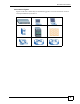
Document Conventions Icons Used in Figures Figures in this User’s Guide may use the following generic icons. The switch icon is not an exact representation of your device.
Safety Warnings Safety Warnings 1 For your safety, be sure to read and follow all warning notices and instructions. For software products: Delete this safety warnings section. For all devices • Do NOT use this product near water, for example, in a wet basement or near a swimming pool. • Do NOT expose your device to dampness, dust or corrosive liquids. • Do NOT store things on the device. • Do NOT install, use, or service this device during a thunderstorm.
Safety Warnings • Do NOT obstruct the device ventilation slots, as insufficient airflow may harm your device. (has ventilation slots) This product is recyclable. Dispose of it properly.
Safety Warnings 8 ES-1528 User’s Guide
Contents Overview Contents Overview Introduction and Hardware Overview .................................................................................. 25 Getting to Know Your Switch ..................................................................................................... 27 Hardware Installation and Connection ....................................................................................... 31 Hardware Overview ...........................................................................
Contents Overview 10 ES-1528 User’s Guide
Table of Contents Table of Contents About This User's Guide .......................................................................................................... 3 Document Conventions............................................................................................................ 4 Safety Warnings........................................................................................................................ 6 Contents Overview .......................................................
Table of Contents 3.3.1 Power Connector ....................................................................................................... 38 3.4 LEDs ................................................................................................................................ 38 Part II: Basic & Advanced Settings ...................................................... 41 Chapter 4 The Web Configurator ..................................................................................................
Table of Contents Chapter 8 VLAN ........................................................................................................................................ 63 8.1 Introduction to IEEE 802.1Q Tagged VLANs .................................................................. 63 8.1.1 Forwarding Tagged and Untagged Frames ................................................................ 63 8.2 Static VLAN .............................................................................................
Table of Contents 13.1 Configuring L2 Management ........................................................................................ 83 13.1.1 Add a Static MAC Address Entry 13.2 Viewing the L2 Address Table ........................................................................... 84 ...................................................................................... 84 Chapter 14 Cable Diagnostics.................................................................................................
Table of Contents 18.3 SNMP User ......................................................................................................................110 18.3.1 SNMP User - Create ..............................................................................................110 18.3.2 SNMP User - Modify ..............................................................................................111 18.4 SNMP Community .........................................................................................
Table of Contents Part IV: Appendices and Index ........................................................... 145 Appendix A Product Specifications....................................................................................... 147 Appendix B IP Addresses and Subnetting ........................................................................... 151 Appendix C Legal Information ..............................................................................................
List of Figures List of Figures Figure 1 Backbone Application .............................................................................................................. 27 Figure 2 Bridging Application ................................................................................................................ 28 Figure 3 High Performance Switched Workgroup Application ............................................................... 29 Figure 4 Shared Server Using VLAN Example .......................
List of Figures Figure 39 DSCP Based QoS ................................................................................................................. 76 Figure 40 ToS Based QoS ..................................................................................................................... 77 Figure 41 IP Address Based QoS ......................................................................................................... 78 Figure 42 Port Rate Limit ...........................................
List of Figures Figure 82 RMON Event Log : Overview. .............................................................................................. 131 Figure 83 RMON Event Log : Event ..................................................................................................... 132 Figure 84 Dynamic ARP ...................................................................................................................... 134 Figure 85 Viewing ARP Table Entries ........................................
List of Figures 20 ES-1528 User’s Guide
List of Tables List of Tables Table 1 Panel Connections .................................................................................................................... 35 Table 2 LEDs ......................................................................................................................................... 38 Table 3 LED Panel .................................................................................................................................
List of Tables Table 39 SNMP Traps .......................................................................................................................... 106 Table 40 SNMP EngineID .................................................................................................................... 107 Table 41 SNMP Group ......................................................................................................................... 108 Table 42 SNMP Group - Create ...............................
List of Tables Table 82 Subnet 4 ................................................................................................................................ 156 Table 83 Eight Subnets ........................................................................................................................ 156 Table 84 24-bit Network Number Subnet Planning .............................................................................. 157 Table 85 16-bit Network Number Subnet Planning .....................
List of Tables 24 ES-1528 User’s Guide
P ART I Introduction and Hardware Overview Getting to Know Your Switch (27) Hardware Installation and Connection (31) Hardware Overview (35) 25
CHAPTER 1 Getting to Know Your Switch This chapter introduces the main features and applications of the switch. 1.1 Introduction The ES-1528 is an Ethernet switch with 24 10/100Mbps ports, two RJ-45 Gigabit ports for stacking and 2 mini-GBIC slots for fiber connections. With its built-in web configurator, managing and configuring the switch is easy. See Appendix A on page 147 for a full list of software features available on the switch. 1.1.
Chapter 1 Getting to Know Your Switch 1.1.2 Bridging Example In this example application the switch connects different company departments (RD and Sales) to the corporate backbone. It can alleviate bandwidth contention and eliminate server and network bottlenecks. All users that need high bandwidth can connect to high-speed department servers via the switch. You can provide a super-fast uplink connection by using a Gigabit Ethernet/mini-GBIC port on the switch.
Chapter 1 Getting to Know Your Switch Figure 3 High Performance Switched Workgroup Application 1.1.4 IEEE 802.1Q VLAN Application Examples A VLAN (Virtual Local Area Network) allows a physical network to be partitioned into multiple logical networks. Stations on a logical network belong to one group. A station can belong to more than one group. With VLAN, a station cannot directly talk to or hear from stations that are not in the same group(s) unless such traffic first goes through a router.
Chapter 1 Getting to Know Your Switch 30 ES-1528 User’s Guide
CHAPTER 2 Hardware Installation and Connection This chapter shows you how to install and connect the switch. 2.1 Freestanding Installation 1 Make sure the switch is clean and dry. 2 Set the switch on a smooth, level surface strong enough to support the weight of the switch and the connected cables. Make sure there is a power outlet nearby. 3 Make sure there is enough clearance around the switch to allow air circulation and the attachment of cables and the power cord.
Chapter 2 Hardware Installation and Connection " Do NOT block the ventilation holes. Leave space between devices when stacking. For proper ventilation, allow at least 4 inches (10 cm) of clearance at the front and 3.4 inches (8 cm) at the back of the switch. This is especially important for enclosed rack installations. 2.2 Mounting the Switch on a Rack This section lists the rack mounting requirements and precautions and describes the installation steps. 2.2.
Chapter 2 Hardware Installation and Connection Figure 6 Attaching the Mounting Brackets 2 Using a #2 Philips screwdriver, install the M3 flat head screws through the mounting bracket holes into the switch. 3 Repeat steps 1 and 2 to install the second mounting bracket on the other side of the switch. 4 You may now mount the switch on a rack. Proceed to the next section. 2.2.
Chapter 2 Hardware Installation and Connection 34 ES-1528 User’s Guide
CHAPTER 3 Hardware Overview This chapter describes the front panel and rear panel of the switch and shows you how to make the hardware connections. 3.1 Panel Connections and the RESET Button The figure below shows the front panel of the switch. Figure 8 Front Panel RJ-45 Gigabit Ports for stacking RESET Button PWR LED LEDs 10/100 Mbps Ethernet Ports Mini-GBIC Slots The following table describes the ports on the panels.
Chapter 3 Hardware Overview There are two Gigabit Ethernet ports. The speed of the Gigabit Ethernet ports can be 10 Mbps, 100Mbps or 1000Mbps and the duplex mode can be half duplex (at 100 Mbps) or full duplex. An auto-negotiating port can detect and adjust to the optimum Ethernet speed (100/ 1000Mpbs) and duplex mode (full duplex or half duplex) of the connected device. An auto-crossover (auto-MDI/MDI-X) port automatically works with a straight-through or crossover Ethernet cable. 3.1.1.
Chapter 3 Hardware Overview 3 The switch automatically detects the installed transceiver. Check the LEDs to verify that it is functioning properly. Figure 10 Installed Transceiver 3.1.2.2 Transceiver Removal Use the following steps to remove a mini GBIC transceiver (SFP module). 1 Open the transceiver’s latch (latch styles vary). Figure 11 Opening the Transceiver’s Latch Example 2 Pull the transceiver out of the slot. Figure 12 Transceiver Removal Example 3.
Chapter 3 Hardware Overview " When you use the RESET button all of your configuration settings will be lost. Use the default IP address (192.168.1.1) and user name (admin) and password (1234) to log back into the switch. It may take up to 2 minutes for the switch to restart when you reload the default configuration file. 3.3 Rear Panel The following figures show the rear panels of the AC power input model switch. The rear panel contains a connector for the power receptacle.
Chapter 3 Hardware Overview Table 2 LEDs (continued) LED COLOR STATUS DESCRIPTION Green On The link to a 10/1000 Mbps Ethernet network is up. Amber On The link to a 100 Mbps Ethernet network is up. Off The link to an Ethernet network is down. On The link to an Ethernet network is up. Blinking The Ethernet port is transmitting/receiving data. Off The link to an Ethernet network is down. On The port has a successful connection. Off No Ethernet device is connected to this port.
Chapter 3 Hardware Overview 40 ES-1528 User’s Guide
P ART II Basic & Advanced Settings The Web Configurator (43) System (49) Port Settings (55) System and Port Statistics (59) VLAN (63) Trunking (67) Mirroring (69) QoS (71) Port Rate Limit and Storm Control (79) Level 2 (L2) Management (83) Cable Diagnostics (87) Auto Denial of Service (DoS) (89) Auto VoIP (93) 41
CHAPTER 4 The Web Configurator This section introduces the configuration and functions of the web configurator. 4.1 Introduction The web configurator is an HTML-based management interface that allows easy switch setup and management via Internet browser. Use Internet Explorer 6.0 and later or Netscape Navigator 7.0 and later versions. The recommended screen resolution is 1024 by 768 pixels. In order to use the web configurator you need to allow: • Web browser pop-up windows from your device.
Chapter 4 The Web Configurator Figure 14 Web Configurator: Login 4 Click LOGIN to view the first web configurator screen. 4.3 The Status Screen The System screen is the first screen that displays when you access the web configurator. The following figure shows the navigating components of the web configurator screen.
Chapter 4 The Web Configurator A - The LED panel displays the port status. B - The navigation panel has links to screens that let you configure the switch features. C - The function frame allows you to view and edit individual feature settings. D - Use the Help link to find out more information about the fields in the screen you are configuring. 4.3.1 The LED Panel Use the LED panel to view the status of the individual ports. The LED panel in the web configurator updates automatically every 5 seconds.
Chapter 4 The Web Configurator Table 4 Navigation Panel Links (continued) LINK DESCRIPTION Statistics Use these screen to view system statistics such as the number of packets received on the switch, collisions and errors and to view statistics for individual ports on the switch. VLAN Use these screens to create new IEEE 802.1Q VLANs as well as view the status and edit existing IEEE 802.1Q VLANs on the switch.
Chapter 4 The Web Configurator Table 4 Navigation Panel Links (continued) LINK ARP Entries Logout DESCRIPTION Use this screen to enter and view MAC address to IP address mappings. Click this to logout of the web configurator. 4.3.3 Change Your Password After you log in for the first time, it is recommended you change the default administrator password. Click System, Password to display the next screen. Figure 17 Change Administrator Login Password 4.
Chapter 4 The Web Configurator The switch is now reinitialized with a default configuration file including the default administrator username (admin) and password (1234). The IP address of the switch also reverts to the default 192.168.1.1. 4.7 Logging Out of the Web Configurator Click Logout in the navigation panel to exit the web configurator. You have to log in with your password again after you log out. This is recommended after you finish a management session for security reasons.
CHAPTER 5 System This chapter describes the system screens. 5.1 System Screen The home screen of the web configurator displays general system information and allows you to perform system maintenance. Click System > Status in the navigation panel to view device specific information such as system name, firmware version and so on. Figure 19 System The following table describes the labels in this screen. Table 5 System LABEL DESCRIPTION Device Name This read-only field displays the name of your switch.
Chapter 5 System Table 5 System (continued) LABEL DESCRIPTION IP Address This field indicates the IP address of the switch. You can click the existing IP address to change it. See Section 5.1.1 on page 50. Note: The DHCP client feature is disabled when you change the IP address manually. Subnet Mask This field indicates the subnet mask of the switch. Gateway This field indicates the IP address of the default gateway.
Chapter 5 System 5.1.2 Level 2 (L2) Table Aging L2 Table Aging defines the aging time of the Address Resolution Logic (ARL) table. This table learns and remembers MAC addresses of devices sending information through it. See Chapter 13 on page 83 for more background information. Click the link in the L2 Table Aging field to see the screen as shown next.
Chapter 5 System Type the path and file name of the configuration file you wish to restore in the Please select a saved configuration file text box or click Browse to display the Choose File screen from which you can locate it. After you have specified the file, click Restore. Make sure you are using the proper configuration when you are restoring your configuration. The file name extension should be “.cfg”. If you attempt to restore a wrong configuration file the following error message appears.
Chapter 5 System 5.3 Firmware Upgrade Make sure you have downloaded (and unzipped) the correct model firmware and version to your computer before uploading to the device. 1 Be sure to upload the correct model firmware as uploading the wrong model firmware may damage your device. From the System screen, click Upgrade in the Firmware Version field to display the screen as shown next.
Chapter 5 System 54 ES-1528 User’s Guide
CHAPTER 6 Port Settings This chapter describes how to view and configure the port settings on the switch. 6.1 Port Status Use this screen to view switch port settings. Click System > Port in the navigation panel to display the Port Status screen. Figure 27 Port Status The following table describes the labels in this screen. Table 8 Port Status LABEL DESCRIPTION Refresh Click this to update the PORT Status screen. Port This identifies the Ethernet port.
Chapter 6 Port Settings Table 8 Port Status (continued) LABEL DESCRIPTION Flow Control Enables access to buffering resources for the port thus ensuring lossless operation across network switches. This field displays either Enabled or Disabled. PVID The PVID field specifies what tag the incoming untagged frames receive on that port so that the frames are forwarded to the VLAN group that the tag defines. 6.2 Port Configuration Use this screen to configure individual port settings.
Chapter 6 Port Settings Table 9 Port Configuration (continued) LABEL DESCRIPTION PVID Enter a number identifying an existing VLAN. The switch tags the incoming untagged frames on that port so that the frames are forwarded to the VLAN group that the tag defines. Apply Click Apply to save your changes to the switch.
Chapter 6 Port Settings 58 ES-1528 User’s Guide
CHAPTER 7 System and Port Statistics This chapter describes the overview and individual port statistics screens. 7.1 Overview The statistics screen of the web configurator displays a port statistical summary with links to each port showing statistical details. 7.2 Statistics Summary Click Statistics in the navigation panel to view the screen as shown. Use this screen to view the traffic counters for the switch. Figure 29 Statistics The following table describes the labels in this screen.
Chapter 7 System and Port Statistics Table 10 Statistics (continued) LABEL DESCRIPTION Port This identifies the Ethernet port. Click a port number to display the Port Details screen (refer to Figure 30 on page 60). Tx This field shows the number of transmitted frames on this port. Rx This field shows the number of received frames on this port. 7.3 Port Statistics Click a number in the Port column in the Statistics screen to display individual port statistics.
Chapter 7 System and Port Statistics Table 11 Status: Port Details (continued) LABEL DESCRIPTION NonUnicastPkts This field shows the number of nonunicast packets transmitted. Discards This field shows the number discarded (dropped) packets. Errors This field shows the number of packets for which transmission failed because of excessive collision. QLength This field shows the number of packets currently buffered. RX The following fields display detailed information about packets received.
Chapter 7 System and Port Statistics Table 11 Status: Port Details (continued) LABEL 62 DESCRIPTION 512-1023 BytePkts This field shows the number of packets (including bad packets) received that were between 512 and 1023 octets in length. 1024-1518 BytePkts This field shows the number of packets (including bad packets) received that were between 1024 and 1522 octets in length.
CHAPTER 8 VLAN This chapter shows you how to configure IEEE 802.1Q tagged VLANs. 8.1 Introduction to IEEE 802.1Q Tagged VLANs A tagged VLAN uses an explicit tag (VLAN ID) in the MAC header to identify the VLAN membership of a frame across bridges - they are not confined to the switch on which they were created. The VLANs can be created statically by hand or dynamically through GVRP.
Chapter 8 VLAN 8.2 Static VLAN Use a IEEE 802.1Q VLAN to decide whether an incoming frame on a port should be • sent to a VLAN group as normal depending on its VLAN tag. • sent to a group whether it has a VLAN tag or not. You can also tag all outgoing frames (that were previously untagged) from a port with the specified VID. 8.2.1 IEEE 802.1Q VLAN Screen See Section 8.1 on page 63 for more information on VLANs. Click VLAN in the navigation panel to display the IEEE 802.1Q VLAN screen as shown next.
Chapter 8 VLAN 8.2.2 Create IEEE 802.1Q VLAN Screen See Section 8.1 on page 63 for more information on VLANs. Click VLAN in the navigation panel to display the IEEE 802.1Q VLAN screen as shown next. Figure 32 VLAN: Create VLAN The following table describes the labels in this screen. Table 13 VLAN: Create VLAN LABEL DESCRIPTION New VLAN ID Enter the VLAN ID of the VLAN you want to create. ALL This button allows you to configure all the ports at once.
Chapter 8 VLAN Figure 33 VLAN: Edit VLAN The following table describes the labels in this screen. Table 14 VLAN: Edit VLAN 66 LABEL DESCRIPTION VLAN ID Select which VLAN you want to configure. Click Remove This VLAN to remove this VLAN from the switch. Display All VLAN Click this button to go back to the VLAN status screen. ALL This button allows you to configure all the ports at once. Click this button to change the state of all the ports at once.
CHAPTER 9 Trunking This chapter shows you how to logically aggregate physical links to form one logical, higherbandwidth link. 9.1 Trunking Overview Trunking is the grouping of physical ports into one logical higher-capacity link. You may want to trunk ports if for example, it is cheaper to use multiple lower-speed links than to underutilize a high-speed, but more costly, single-port link. However, the more ports you aggregate then the fewer available ports you have.
Chapter 9 Trunking Figure 34 Trunk Setting The following table describes the labels in this screen. Table 15 Trunking: Configuration LABEL DESCRIPTION Distribution Criterion Trunking uses a distribution algorithm to balance traffic between trunk members. Select the traffic distribution algorithm between trunk member ports. Your choices are: • SA (Source MAC Address) • DA (Destination MAC Address) • SA + DA Modify Trunk Group Member Configure the following settings to create and modify trunk groups.
CHAPTER 10 Mirroring This chapter discusses port mirroring. 10.1 Port Mirroring Settings Port mirroring allows you to copy traffic flow to a monitor port (the port you copy the traffic to) in order that you can examine the traffic from the mirrored port without interference. Click Mirror in the navigation panel to display the Mirror Setting screen. Use this screen to select a monitor port and specify the traffic flow to be copied to the monitor port.
Chapter 10 Mirroring 70 ES-1528 User’s Guide
CHAPTER 11 QoS This chapter introduces the quality of service (QoS) parameters you can configure on the switch. 11.1 QoS Overview QoS is used to help solve performance degradation when there is network congestion. Use the QoS Setting screen to configure queuing algorithms for outgoing traffic. Queuing algorithms allow switches to maintain separate queues for packets from each individual source or flow and prevent a source from monopolizing the bandwidth. 11.1.
Chapter 11 QoS 11.2 QoS Enhancement You can configure the switch to prioritize traffic even if the incoming packets are not marked with IEEE 802.1p priority tags or change the existing priority tags based on the criteria you select. The switch allows you to choose one of the following methods for assigning priority to incoming packets on the switch: Port Based QoS - Assign priority to packets based on the incoming port on the switch. See Section 11.4.1 on page 74.
Chapter 11 QoS The following table describes the labels in this screen. Table 17 QoS Setting LABEL DESCRIPTION Advanced Click this link to configure QoS settings based on port number, IP address or configure DSCP or ToS priority to 802.1p priority mappings. Number of queues This field displays the number of queues configurable on the switch. Click Change to edit the number of queues on the switch. Scheduling Method Select Strict Priority or Weighted Round Robin.
Chapter 11 QoS 11.4 Advanced QoS Settings The following sections describe additional methods for setting priority for incoming packets on the ports. The switch allows you to choose one of the following methods: " Advanced QoS methods only affect the internal priority queue mapping for the switch. The switch does not modify the IEEE 802.1p value for the egress frames. 11.4.1 Port Based QoS You can configure the switch to assign a IEEE 802.
Chapter 11 QoS The following table describes the labels in this screen. Table 18 Port Based QoS LABEL DESCRIPTION Mode Select Port Based QoS to specify priority rules based on the port of incoming packets. Change Priority Configure the following: • Port - Select the number of the port for which you want to assign IEEE 802.1p priority to incoming frames. • Priority - Select the IEEE 802.1p priority you want to assign to the packets coming into the switch on the port specified in the Port field.
Chapter 11 QoS Figure 39 DSCP Based QoS The following table describes the labels in this screen. Table 19 DSCP Based QoS LABEL DESCRIPTION Mode Select DSCP Based QoS to specify mapping rules between DSCP priority and IEEE 802.1p priority for incoming packets on the switch. Change Priority Configure the following: • DSCP - Select the DSCP priority for which you want to change a priority mapping. • Priority - Select the IEEE 802.
Chapter 11 QoS Figure 40 ToS Based QoS The following table describes the labels in this screen. Table 20 ToS Based QoS LABEL DESCRIPTION Mode Select ToS Based QoS to specify mapping rules between ToS priority and IEEE 802.1p priority for incoming packets on the switch. Change Priority Configure the following: • TOS - Select the ToS priority for which you want to change a priority mapping. • Priority - Select the IEEE 802.
Chapter 11 QoS Figure 41 IP Address Based QoS The following table describes the labels in this screen. Table 21 IP Address Based QoS LABEL DESCRIPTION Mode Select IP Address Based QoS to give higher or lower priority to packets coming into the switch from a specified source IP address. Add Entry Enter the IP address and the subnet mask of the source whose traffic you want to assign a priority to in the IP and MASK fields respectively. Select the Priority value and click Add.
CHAPTER 12 Port Rate Limit and Storm Control This chapter shows you how you can manage bandwidth on each port and set up broadcast storm control settings using the Port Rate and Storm Control screens. 12.1 Port Rate Screen Rate control means defining a maximum allowable bandwidth for incoming and/or out-going traffic flows on a port. Click Rate > Port Rate in the navigation panel to bring up the screen as shown next.
Chapter 12 Port Rate Limit and Storm Control Table 22 Rate Limit and Storm Control (continued) LABEL DESCRIPTION Ingress Rate Displays the maximum bandwidth allowed in kilobits per second (Kbps) for the incoming traffic flow on a port. Egress Rate Displays the maximum bandwidth allowed in kilobits per second (Kbps) for the outgoing traffic flow on a port. 12.1.1 Rate Limit Screen Click a port number in the Port Rate screen to bring up the screen as shown next.
Chapter 12 Port Rate Limit and Storm Control Table 23 Rate Limit Configuration (continued) LABEL DESCRIPTION Burst Size The burst size specifies the maximum amount of traffic that can be allowed out the port at any one instance. In the “Token Bucket” algorithm this is referred to as the size of the bucket as this value limits the number of tokens that can accumulate in the bucket. Apply Click this to save your changes to the switch. 12.1.
Chapter 12 Port Rate Limit and Storm Control The following table describes the labels in this screen. Table 24 Broadcast Storm Control 82 LABEL DESCRIPTION Port Select the port number for which you want to configure storm control settings or select Apply settings to all ports to configure all the ports at once. Storm Control Type Select Disabled - to turn off this feature. Broadcast only - to only specify a limit for the amount of broadcast packets received per second.
CHAPTER 13 Level 2 (L2) Management Use these screens to add, delete and view entries in the Level 2 (L2) address table. 13.1 Configuring L2 Management Level 2 (L2) management refers to management based on the Media Access Control (MAC) address of networking devices. A static Media Access Control (MAC) address is an address that has been manually entered in the MAC address table. Static MAC addresses do not age out. When you set up static MAC address rules, you are setting static MAC addresses for a port.
Chapter 13 Level 2 (L2) Management Table 25 L2 Management (continued) LABEL DESCRIPTION Port This field displays the port number of a manually entered MAC address entry. Delete Click DELETE to remove this manually entered MAC address entry from the MAC address table. 13.1.1 Add a Static MAC Address Entry Click Add in the L2 Address Management screen to display the configuration screen as shown. Figure 46 Add a Static MAC Entry The following table describes the labels in this screen.
Chapter 13 Level 2 (L2) Management Figure 47 Display L2 Address Table The following table describes the labels in this screen. Table 27 Display L2 Address Table LABEL DESCRIPTION Reload Address Table Click this to update all the fields in the L2 Address table. Item This is the index number of the MAC address entry. Source MAC This field displays the MAC address. VID This field displays the VID of a manually entered MAC address entry.
Chapter 13 Level 2 (L2) Management 86 ES-1528 User’s Guide
CHAPTER 14 Cable Diagnostics This chapter explains the Cable Diagnostics screen. 14.1 Diagnostics Overview The cable diagnostics function works with systems using CAT-5 twisted-pair cables. The switch can perform basic cable diagnostics. Click Cable Diagnostic in the navigation panel to view the screen as shown. Figure 48 Cable Diagnostic The following table describes the labels in this screen. Table 28 Cable Diagnostic LABEL DESCRIPTION Port to diagnose Select the port you want to test.
Chapter 14 Cable Diagnostics 88 ES-1528 User’s Guide
CHAPTER 15 Auto Denial of Service (DoS) This chapter shows you how to configure automatic Denial of Service prevention on the switch. 15.1 About Denial of Service Attacks Denial of Service (DoS) attacks try to disable a device or network so users no longer have access to network resources. The switch has features which automatically detect and thwart currently known DoS attacks. 15.1.1 DoS Attacks Summary The following table summarizes the types of attacks the switch can prevent.
Chapter 15 Auto Denial of Service (DoS) 15.2 Global Auto DoS Attack Prevention Use the Global Auto DoS Attack Prevention screen to configure DoS attack prevention settings for the switch. Click Auto DoS in the navigation panel to open the following screen. Figure 49 Global Auto DoS Attack Prevention The following table describes the labels in this screen. Table 30 Global Auto DoS Attack Prevention LABEL DESCRIPTION Advanced Click this link to configure advance Auto DoS settings.
Chapter 15 Auto Denial of Service (DoS) Figure 50 Advanced Auto DoS Attack Prevention The following table describes the labels in this screen. Table 31 Advanced Auto DoS Attack Prevention LABEL DESCRIPTION Global Click this link to view the Global Auto DoS Attack Prevention screen. Port Select the port you want to configure or select Apply settings to all ports to configure all the ports on the switch.
Chapter 15 Auto Denial of Service (DoS) 92 ES-1528 User’s Guide
CHAPTER 16 Auto VoIP This chapter shows you how to give higher priority to Voice over Internet Protocol (VoIP) packets over other data packets as they pass through the switch. 16.1 About Auto VoIP Voice over Internet Protocol (VoIP) allows telephone calls to be made over a data network like the Internet.
Chapter 16 Auto VoIP Figure 51 Auto VoIP Settings The following table describes the labels in this screen. Table 32 Auto VoIP Settings 94 LABEL DESCRIPTION Profiles Select Disable if you don’t want to give higher priority to VoIP traffic or select IP Phone to give the highest priority to SIP, MGCP and SCCP packets passing through the switch. Apply Click Apply to save your changes to the switch.
P ART III Management and Troubleshooting Event Logging (97) SNMP (105) RMON-Lite (119) Dynamic ARP (133) Troubleshooting (137) 95
CHAPTER 17 Event Logging This chapter shows you different ways to inspect logs and how to configure an external log server. 17.1 Event Logging Overview You can configure the switch to save specific events in four different log targets: RAM - This log is saved into the switch’s volatile memory. The logs are cleared when the switch is rebooted. Flash - This log is saved into the switch’s non-volatile memory. You can view the logs even after the switch is rebooted.
Chapter 17 Event Logging Figure 52 Logging The following table describes the labels in this screen. Table 33 Logging LABEL DESCRIPTION Add Server Click this to configure a new syslog server. Logging Target Click the RAM or Flash links to view the logs stored on the switch. Use the columns on the right to select the types of system events each logging target should record.
Chapter 17 Event Logging Figure 53 Logging - Add Server The following table describes the labels in this screen. Table 34 Logging - Add Server LABEL DESCRIPTION Name Enter a short descriptive name for identifying this server. IP Address Enter the IP address in dotted decimal notation of the syslog server you want to add. Port Specify the UDP port for sending log messages to this server. Typically port 514 is used with syslog.
Chapter 17 Event Logging The following table describes the labels in this screen. Table 35 Logging - RAM/Flash LABEL DESCRIPTION Search Click this to search for specific log entries. Export Click this to export (save) the log. The logs default name is “events.csv”. A .csv (Comma Separated Values) file can be viewed by most spreadsheet software such as Microsoft’s Excel. No. This is the number of the log entry. The log entries with the lowest numerical value are the most recent.
Chapter 17 Event Logging Figure 55 Searching - RAM/Flash Logs ES-1528 User’s Guide 101
Chapter 17 Event Logging The following table describes the labels in this screen. Table 36 Searching - RAM/Flash Logs LABEL DESCRIPTION Level Select the severity level(s) of the log events you want to find. The possible severity levels are: • Error - to search system failures, such as events which will cause the switch to malfunction and events such as invalid user input in the web configurator. • Warning - to search non critical errors on the switch.
Chapter 17 Event Logging Table 37 Logs: Search Results (continued) LABEL DESCRIPTION Category This field displays what category the log entry fits. The categories are based on software and hardware features of the switch. For example the category AUTODOS records events which deal with the Auto Denial of Service features you set up and the category SYSTEM records events which deal with the overall operation of the switch. Time This field specifies the time when the switch recorded the log event.
Chapter 17 Event Logging 104 ES-1528 User’s Guide
CHAPTER 18 SNMP This chapter describes how to user Simple Network Management Protocol (SNMP) to manage and monitor the switch. 18.1 About SNMP Simple Network Management Protocol (SNMP) is an application layer protocol used to manage and monitor TCP/IP-based devices. SNMP is used to exchange management information between the network management system (NMS) and a network element (NE).
Chapter 18 SNMP SNMP itself is a simple request/response protocol based on the manager/agent model. The manager issues a request and the agent returns responses using the following protocol operations: Table 38 SNMP Commands COMMAND DESCRIPTION Get Allows the manager to retrieve an object variable from the agent. GetNext Allows the manager to retrieve the next object variable from a table or list within an agent.
Chapter 18 SNMP 18.1.3 SNMP v3 and Authentication SNMP v3 adds the use of groups and users to enhance security for SNMP management. Groups are assigned access rights to SNMP objects. Users are members of groups and are therefore limited to the access rights the group has. In addition users can also be required to authenticate before conducting SNMP management sessions. " SNMP v3 is enabled by creating SNMP groups and users.
Chapter 18 SNMP Figure 59 SNMP Group The following table describes the labels in this screen. Table 41 SNMP Group LABEL DESCRIPTION Group ID Select the SNMP group you want to edit. Create New Group Click this to configure a new SNMP group. Group ID This field indicates the group number. It is used for identification only. Click on the individual group number to edit the group settings. Group Name This field displays the name of the SNMP group.
Chapter 18 SNMP The following table describes the labels in this screen. Table 42 SNMP Group - Create LABEL DESCRIPTION Group Name Specify the name for this SNMP group. SNMP Version Specify the SNMP version this group uses to manage the switch. Authentication This field is only editable if you select SNMPv3 in the SNMP Version field. Select Enabled to force SNMP v3 groups to authenticate with the switch or select Disabled to deactivate authentication for the SNMP v3 groups.
Chapter 18 SNMP Table 43 SNMP Group - Modify (continued) LABEL DESCRIPTION Access Read - select Enabled to allow this group to collect information from this switch. Write - select Enabled to allow this group to create or edit SNMP objects. Apply Click this to save your settings to the switch. 18.3 SNMP User SNMP users are used to define the security parameters of SNMP clients in an SNMP v3 environment. Each SNMP user is a member of a predefined SNMP group.
Chapter 18 SNMP Figure 63 SNMP User - Create The following table describes the labels in this screen. Table 45 SNMP User - Create LABEL DESCRIPTION User Name Specify the name for this SNMP user. Group Name Specify the SNMP group this user belongs to. SNMP Version Specify the SNMP version this group uses to manage the switch. Auth Type Authentication can only be configured for SNMP v3.
Chapter 18 SNMP The following table describes the labels in this screen. Table 46 SNMP User - Modify LABEL DESCRIPTION User ID This field indicates which user you are modifying. Click on Remove This User to delete this user configuration from the switch. Click on Display All User to view the main SNMP User screen. User Name Edit the name for this SNMP user. Group Name Select the SNMP group this user should belong to. SNMP Version Specify the SNMP version this group uses to manage the switch.
Chapter 18 SNMP Table 47 SNMP Community (continued) LABEL DESCRIPTION Community String This field indicates the SNMP community string. An SNMP community string is a text string that acts as a password. It is used to authenticate messages that are sent between the management station (the SNMP manager) and the device (the SNMP agent). The community string is included in every packet that is transmitted between the SNMP manager and the SNMP agent.
Chapter 18 SNMP Figure 67 SNMP Community - Modify The following table describes the labels in this screen. Table 49 SNMP Community - Modify LABEL DESCRIPTION User ID This field indicates which community you are modifying. Click on Remove This Community to delete this user configuration from the switch. Click on Display All Community to view the main SNMP Community screen. Community String An SNMP community string is a text string that acts as a password.
Chapter 18 SNMP Figure 68 SNMP Notification The following table describes the labels in this screen. Table 50 SNMP Notification LABEL DESCRIPTION Enable SNMP Notification Select this to enable the sending of SNMP traps to a remote SNMP management station. Enable Authentication Notification Select this to enable logging of failed authentication attempts. Apply Click this to save your settings to the switch. 18.
Chapter 18 SNMP Figure 69 SNMP Trap Station The following table describes the labels in this screen. Table 51 SNMP Trap Station LABEL DESCRIPTION Trap Station ID Select the SNMP trap station you want to edit. Create New Trap Station Click this to configure a new SNMP Trap Station. Trap Station ID This field indicates the trap station number. It is used for identification only. Click on the individual trap station number to edit the trap station settings.
Chapter 18 SNMP The following table describes the labels in this screen. Table 52 SNMP Trap Station - Create LABEL DESCRIPTION Remote IP Address Enter the IP address of the remote trap station in dotted decimal notation. Community String Specify the community string used with this remote trap station. Create Click this to add this SNMP user to the switch. Cancel Click this to go back to the main SNMP Group screen without saving your changes. 18.6.
Chapter 18 SNMP 118 ES-1528 User’s Guide
CHAPTER 19 RMON-Lite This chapter explains how to configure the RMON-Lite screens. 19.1 RMON-Lite Overview The Remote Network Monitoring Management Information Base (RMON MIB) defines objects for managing remote network monitoring devices. The remote network monitoring devices, referred to as monitors or probes, are usually stand-alone devices and devote significant internal resources for the purposes of managing a network. There are a total of nine RMON MIB groups defined in RFC 2819.
Chapter 19 RMON-Lite Figure 72 RMON Statistics : Overview The following table describes the labels in this screen. Table 54 RMON Statistics : Overview LABEL DESCRIPTION RMON MIB Table: Use this drop down list box to select the MIB table you want to view. Click Apply to refresh the screen to the selected MIB table view. Refresh Click this to update all the fields in the RMON-Lite Statistics : Overview screen. Data Source This field displays the ports on the switch.
Chapter 19 RMON-Lite Figure 73 RMON Statistics : Port The following table describes the labels in this screen. Table 55 RMON Statistics : Port LABEL DESCRIPTION RMON MIB Table: Use this drop down list box to select the MIB table you want to view. Click Apply to refresh the screen to the selected MIB table view. Set Enable Click this to activate statistics gathering for this port. Clear Click this to reset all statistics values to “0”.
Chapter 19 RMON-Lite Table 55 RMON Statistics : Port (continued) LABEL DESCRIPTION StatsJabbers This field displays the number of frames dropped because they were longer than 1518 octets and contained an invalid FCS, including alignment errors. StatsCollisions This field displays the total number of collisions occurred. StatsPkts64Octets This field displays the number of packets (including bad packets) received that were 64 octets in length.
Chapter 19 RMON-Lite Figure 74 RMON History Control : Overview. The following table describes the labels in this screen. Table 56 RMON History Control : Overview. LABEL DESCRIPTION RMON MIB Table: Use this drop down list box to select the MIB table you want to view. Click Apply to refresh the screen to the selected MIB table view. Refresh Click this to update all the fields in the RMON History Control : Overview screen. Index This field displays the configuration index number.
Chapter 19 RMON-Lite Figure 75 RMON History Control : Modify The following table describes the labels in this screen. Table 57 RMON History Control : Modify LABEL DESCRIPTION RMON MIB Table: Use this drop down list box to select the MIB table you want to view. Click Apply to refresh the screen to the selected MIB table view. Index This field displays the entry index number. Data Source This field displays the port number associated with the Index entry.
Chapter 19 RMON-Lite Figure 76 RMON History Statistics : Overview. The following table describes the labels in this screen. Table 58 RMON History Statistics : Overview LABEL DESCRIPTION RMON MIB Table: Use this drop down list box to select the MIB table you want to view. Click Apply to refresh the screen to the selected MIB table view. Refresh Click this to update all the fields in the RMON History Statistics : Overview screen.
Chapter 19 RMON-Lite Figure 77 RMON History Statistics: Control The following table describes the labels in this screen. Table 59 RMON History Statistics: Control 126 LABEL DESCRIPTION RMON MIB Table: Use this drop down list box to select the MIB table you want to view. Click Apply to refresh the screen to the selected MIB table view. Refresh Click this to update all the fields in the RMON History Statistics : Control Index screen.
Chapter 19 RMON-Lite Table 59 RMON History Statistics: Control (continued) LABEL DESCRIPTION Utilization (%) This field displays the utilization as a percentage of maximum utilization allowed on the port in this polling sample. History Statistics Overview Click this to go back to the RMON History Statistics: Overview screen. 19.5 RMON Alarm: Overview Use the RMON Alarm: Overview screen to view configured alarms that occur when the sampled data exceeds the specified threshold.
Chapter 19 RMON-Lite Table 60 RMON Alarm: Overview (continued) LABEL DESCRIPTION RisingThreshol d This field displays the rising threshold value set up for this alarm. FallingThreshol d This field displays the falling threshold value set up for this alarm. Rising Event Index This field indicates the index number of the event entry which corresponds to the time when the alarm threshold was crossed.
Chapter 19 RMON-Lite Table 61 RMON Alarm : Create New Alarm (continued) LABEL DESCRIPTION Interface Select the port which is monitored for this alarm. Counter Select the data which is used to test if this alarm is triggered, the choices are Drop Events, Octets, Packets and so on. Sample Type Select the method of obtaining the sample value. Choices are Absolute and Value. Startup Alarm Select the startup alarm type (Rising Threshold, Falling Threshold, Rising Or Falling Threshold).
Chapter 19 RMON-Lite Table 62 RMON Event : Overview (continued) LABEL DESCRIPTION Description This field displays a description of the event. Type This field displays the event type (1:None, 2:Log, 3:SNMP-Trap, 4:Log-and-Trap). Community This field displays the community or SNMP trap. Last Time Sent This field indicates the value of system up time on the switch when this event was last generated.
Chapter 19 RMON-Lite Table 63 RMON Event Configuration Screens (continued) LABEL DESCRIPTION Description Enter a description of the event. You can use 1-127 printable ASCII characters. Spaces are allowed. You can also leave this field blank. Type Select an event type: • None to do nothing. • Log to generate a log when an associated alarm is generated. • Trap to generate a trap when an associated alarm is generated. • Log and Trap to generate a log entry and trap when an associated alarm is generated.
Chapter 19 RMON-Lite Table 64 RMON Event Log : Overview (continued) LABEL DESCRIPTION Last Time Sent This field indicates the value of system up time on the switch when this event was last generated. It appears in the following format “XXD: XXH: XXM: XXS”, where “XX” stands for a number and “D” stands for days, “H” for hours, “M” for minutes and “S” for seconds. Owner This field displays the entry creator. It displays “monitor” if the entry was created by the switch itself. 19.7.
CHAPTER 20 Dynamic ARP This chapter describes how to activate dynamic Address Resolution Protocol (ARP) learning and how to enter static ARP table entries. 20.1 ARP Table Overview Address Resolution Protocol (ARP) is a protocol for mapping an Internet Protocol address (IP address) to a physical machine address, also known as a Media Access Control or MAC address, on the local area network. An IP (version 4) address is 32 bits long. In an Ethernet LAN, MAC addresses are 48 bits long.
Chapter 20 Dynamic ARP 20.2 Enabling Dynamic ARP Click Dynamic ARP > Settings in the navigation panel to open the following screen. Use the Dynamic ARP screen to configure ARP filtering on the specified VLANs. Figure 84 Dynamic ARP The following table describes the labels in this screen. Table 66 ARP Table 134 LABEL DESCRIPTION Enable Dynamic ARP Select or deselect this to activate or deactivate Dynamic ARP on the switch.
Chapter 20 Dynamic ARP 20.3 Viewing ARP Table Entries Click Dynamic ARP > ARP Entries in the navigation panel to open the following screen. Use this screen to view and add entries to the ARP table. Figure 85 Viewing ARP Table Entries The following table describes the labels in this screen. Table 67 ARP Table LABEL DESCRIPTION Static MAC-IP binding: ADD This field is only available when you enable dynamic ARP in the Dynamic ARP > Settings screen. Click ADD to add a static entry to the ARP table.
Chapter 20 Dynamic ARP Figure 86 Viewing ARP Table Entries The following table describes the labels in this screen. Table 68 ARP Table 136 LABEL DESCRIPTION MAC Address (XX-XX-XXXX-XX-XX) Enter the MAC address in 6 pair hexadecimal format of the network device you want to be allowed to communicate via the switch. An example entry of a MAC address is “0ab1-c2-d3-e4-f5”. IP Address Enter the corresponding IP address (in dotted decimal notation, ex 192.168.1.
CHAPTER 21 Troubleshooting This chapter covers potential problems and possible remedies. 21.1 Problems Starting Up the Switch Table 69 Troubleshooting the Start-Up of Your Switch PROBLEM CORRECTIVE ACTION None of the LEDs Check the power connection and make sure the power source is turned on. turn on when you turn on the switch. If the error persists, you may have a hardware problem. In this case, you should contact your vendor. 21.
Chapter 21 Troubleshooting " Internet Explorer 6 screens are used here. Screens for other Internet Explorer versions may vary. 21.2.1.1 Internet Explorer Pop-up Blockers You may have to disable pop-up blocking to log into your device. Either disable pop-up blocking (enabled by default in Windows XP SP (Service Pack) 2) or allow pop-up blocking and create an exception for your device’s IP address. 21.2.1.1.
Chapter 21 Troubleshooting Figure 88 Internet Options 3 Click Apply to save this setting. 21.2.1.1.2 Enable pop-up Blockers with Exceptions Alternatively, if you only want to allow pop-up windows from your device, see the following steps. 1 In Internet Explorer, select Tools, Internet Options and then the Privacy tab. 2 Select Settings…to open the Pop-up Blocker Settings screen.
Chapter 21 Troubleshooting Figure 89 Internet Options 3 Type the IP address of your device (the web page that you do not want to have blocked) with the prefix “http://”. For example, http://192.168.1.1. 4 Click Add to move the IP address to the list of Allowed sites. Figure 90 Pop-up Blocker Settings 5 Click Close to return to the Privacy screen.
Chapter 21 Troubleshooting 6 Click Apply to save this setting. 21.2.1.2 JavaScripts If pages of the web configurator do not display properly in Internet Explorer, check that JavaScripts are allowed. 1 In Internet Explorer, click Tools, Internet Options and then the Security tab. Figure 91 Internet Options 2 3 4 5 6 Click the Custom Level... button. Scroll down to Scripting. Under Active scripting make sure that Enable is selected (the default).
Chapter 21 Troubleshooting Figure 92 Security Settings - Java Scripting 21.2.1.3 Java Permissions 1 2 3 4 5 From Internet Explorer, click Tools, Internet Options and then the Security tab. Click the Custom Level... button. Scroll down to Microsoft VM. Under Java permissions make sure that a safety level is selected. Click OK to close the window.
Chapter 21 Troubleshooting 21.2.1.3.1 JAVA (Sun) 1 From Internet Explorer, click Tools, Internet Options and then the Advanced tab. 2 make sure that Use Java 2 for
Chapter 21 Troubleshooting 144 ES-1528 User’s Guide
P ART IV Appendices and Index This part contains the following chapters.
APPENDIX A Product Specifications This section describes the general software features of the switch. Table 71 Firmware Features FEATURE DESCRIPTION VLAN A VLAN (Virtual Local Area Network) allows a physical network to be partitioned into multiple logical networks. Devices on a logical network belong to one group. A device can belong to more than one group. With VLAN, a device cannot directly talk to or hear from devices that are not in the same group(s); the traffic must first go through a router.
Appendix A Product Specifications Table 71 Firmware Features FEATURE DESCRIPTION Dynamic ARP Dynamic ARP allows you to filter incoming traffic based on the MAC to IP address mapping. The switch can be configured to only allow trusted devices to communicate via its ports. RMON-Lite Remote Network Monitoring Management (RMON) allows you to gather information about the switch’s performance, view statistics and create alarms.
Appendix A Product Specifications Table 73 Management Specifications System Control Alarm/Status surveillance LED indication for power status Performance monitoring Line speed Four RMON groups (history, statistics, alarms, and events) Throughput monitoring Port mirroring and aggregation Firmware upgrade and download through HTTP FLASH memory Reset to default button Network Management Web-based management SNMP v1, v2c and v3; 10 Trap Stations supported RMON groups (history, statistics, alarms and events)
Appendix A Product Specifications 150 ES-1528 User’s Guide
APPENDIX B IP Addresses and Subnetting This appendix introduces IP addresses and subnet masks. IP addresses identify individual devices on a network. Every networking device (including computers, servers, routers, printers, etc.) needs an IP address to communicate across the network. These networking devices are also known as hosts. Subnet masks determine the maximum number of possible hosts on a network. You can also use subnet masks to divide one network into multiple sub-networks.
Appendix B IP Addresses and Subnetting Figure 95 Network Number and Host ID How much of the IP address is the network number and how much is the host ID varies according to the subnet mask. Subnet Masks A subnet mask is used to determine which bits are part of the network number, and which bits are part of the host ID (using a logical AND operation). The term “subnet” is short for “subnetwork”. A subnet mask has 32 bits.
Appendix B IP Addresses and Subnetting Subnet masks are expressed in dotted decimal notation just like IP addresses. The following examples show the binary and decimal notation for 8-bit, 16-bit, 24-bit and 29-bit subnet masks. Table 76 Subnet Masks BINARY DECIMAL 1ST OCTET 2ND OCTET 3RD OCTET 4TH OCTET 8-bit mask 11111111 00000000 00000000 00000000 255.0.0.0 16-bit mask 11111111 11111111 00000000 00000000 255.255.0.0 24-bit mask 11111111 11111111 11111111 00000000 255.255.255.
Appendix B IP Addresses and Subnetting Table 78 Alternative Subnet Mask Notation (continued) SUBNET MASK ALTERNATIVE NOTATION LAST OCTET (BINARY) LAST OCTET (DECIMAL) 255.255.255.192 /26 1100 0000 192 255.255.255.224 /27 1110 0000 224 255.255.255.240 /28 1111 0000 240 255.255.255.248 /29 1111 1000 248 255.255.255.252 /30 1111 1100 252 Subnetting You can use subnetting to divide one network into multiple sub-networks.
Appendix B IP Addresses and Subnetting Figure 97 Subnetting Example: After Subnetting In a 25-bit subnet the host ID has 7 bits, so each sub-network has a maximum of 27 – 2 or 126 possible hosts (a host ID of all zeroes is the subnet’s address itself, all ones is the subnet’s broadcast address). 192.168.1.0 with mask 255.255.255.128 is subnet A itself, and 192.168.1.127 with mask 255.255.255.128 is its broadcast address.
Appendix B IP Addresses and Subnetting Table 80 Subnet 2 IP/SUBNET MASK NETWORK NUMBER LAST OCTET BIT VALUE IP Address 192.168.1. 64 IP Address (Binary) 11000000.10101000.00000001. 01000000 Subnet Mask (Binary) 11111111.11111111.11111111. 11000000 Subnet Address: 192.168.1.64 Lowest Host ID: 192.168.1.65 Broadcast Address: 192.168.1.127 Highest Host ID: 192.168.1.126 Table 81 Subnet 3 IP/SUBNET MASK NETWORK NUMBER LAST OCTET BIT VALUE IP Address 192.168.1.
Appendix B IP Addresses and Subnetting Table 83 Eight Subnets (continued) SUBNET SUBNET ADDRESS FIRST ADDRESS LAST ADDRESS BROADCAST ADDRESS 5 128 129 158 159 6 160 161 190 191 7 192 193 222 223 8 224 225 254 255 Subnet Planning The following table is a summary for subnet planning on a network with a 24-bit network number. Table 84 24-bit Network Number Subnet Planning NO. “BORROWED” HOST BITS SUBNET MASK NO. SUBNETS NO. HOSTS PER SUBNET 1 255.255.255.128 (/25) 2 126 2 255.
Appendix B IP Addresses and Subnetting Table 85 16-bit Network Number Subnet Planning (continued) NO. “BORROWED” HOST BITS SUBNET MASK NO. SUBNETS NO. HOSTS PER SUBNET 14 255.255.255.252 (/30) 16384 2 15 255.255.255.254 (/31) 32768 1 Configuring IP Addresses Where you obtain your network number depends on your particular situation. If the ISP or your network administrator assigns you a block of registered IP addresses, follow their instructions in selecting the IP addresses and the subnet mask.
APPENDIX C Legal Information Copyright Copyright © 2006 by ZyXEL Communications Corporation. The contents of this publication may not be reproduced in any part or as a whole, transcribed, stored in a retrieval system, translated into any language, or transmitted in any form or by any means, electronic, mechanical, magnetic, optical, chemical, photocopying, manual, or otherwise, without the prior written permission of ZyXEL Communications Corporation. Published by ZyXEL Communications Corporation.
Appendix C Legal Information FCC Warning This device has been tested and found to comply with the limits for a Class A digital switch, pursuant to Part 15 of the FCC Rules. These limits are designed to provide reasonable protection against harmful interference in a commercial environment. This device generates, uses, and can radiate radio frequency energy and, if not installed and used in accordance with the instruction manual, may cause harmful interference to radio communications.
Appendix C Legal Information ZyXEL Limited Warranty ZyXEL warrants to the original end user (purchaser) that this product is free from any defects in materials or workmanship for a period of up to two years from the date of purchase.
Appendix C Legal Information 162 ES-1528 User’s Guide
APPENDIX D Customer Support Please have the following information ready when you contact customer support. Required Information • • • • Product model and serial number. Warranty Information. Date that you received your device. Brief description of the problem and the steps you took to solve it. Corporate Headquarters (Worldwide) • • • • • • • Support E-mail: support@zyxel.com.tw Sales E-mail: sales@zyxel.com.tw Telephone: +886-3-578-3942 Fax: +886-3-578-2439 Web Site: www.zyxel.com, www.europe.zyxel.
Appendix D Customer Support Denmark • • • • • • Support E-mail: support@zyxel.dk Sales E-mail: sales@zyxel.dk Telephone: +45-39-55-07-00 Fax: +45-39-55-07-07 Web Site: www.zyxel.dk Regular Mail: ZyXEL Communications A/S, Columbusvej, 2860 Soeborg, Denmark Finland • • • • • • Support E-mail: support@zyxel.fi Sales E-mail: sales@zyxel.fi Telephone: +358-9-4780-8411 Fax: +358-9-4780 8448 Web Site: www.zyxel.
Appendix D Customer Support • • • • Telephone: +7-3272-590-698 Fax: +7-3272-590-689 Web Site: www.zyxel.kz Regular Mail: ZyXEL Kazakhstan, 43, Dostyk ave.,Office 414, Dostyk Business Centre, 050010, Almaty, Republic of Kazakhstan North America • • • • • • • Support E-mail: support@zyxel.com Sales E-mail: sales@zyxel.com Telephone: +1-800-255-4101, +1-714-632-0882 Fax: +1-714-632-0858 Web Site: www.us.zyxel.com FTP Site: ftp.us.zyxel.com Regular Mail: ZyXEL Communications Inc., 1130 N. Miller St.
Appendix D Customer Support • Web Site: www.zyxel.es • Regular Mail: ZyXEL Communications, Arte, 21 5ª planta, 28033 Madrid, Spain Sweden • • • • • • Support E-mail: support@zyxel.se Sales E-mail: sales@zyxel.se Telephone: +46-31-744-7700 Fax: +46-31-744-7701 Web Site: www.zyxel.se Regular Mail: ZyXEL Communications A/S, Sjöporten 4, 41764 Göteborg, Sweden Ukraine • • • • • • Support E-mail: support@ua.zyxel.com Sales E-mail: sales@ua.zyxel.
Index Index A adding VLANs 65 Address Resolution Logic (ARL) table 51 Address Resolution Protocol (ARP) 133 allowing pop-up windows 137 alternative subnet mask notation 153 applications backbone 27 bridging 28 IEEE 802.
Index firmware version 49 Flash logs 97 flow control 56 back pressure 56 IEEE802.
Index N R NAT 158 network management 149 network management system (NMS) 105 RAM logs 97 registration product 161 related documentation 3 Remote Network Monitoring Management Information Base (RMON MIB) 119 reset 53 reset button 35, 47 default configuration 37 resetting 47 restart 53 restoring configuration 47, 51 RMON alarm group 127 event group 129 history group 122 statistics group 119 RMON-Lite 119 Round Robin Scheduling 71 rubber feet 31 O open, cable fault 87 P password 47 pop-up Windows, allowi
Index SNMP traps 106 SP (Strict Priority) queuing 71 start-up problems 137 static MAC address 83 static MAC forwarding 83, 84 status 44 LED 38 port details 53, 60 VLAN 64, 66 subnet 151 subnet mask 152 subnetting 154 switch lockout 47 switch reset 47 switching 148 syntax conventions 4 system control 149 system status 49 tagged 63 tagged and untagged 65 W warranty 161 note 161 web configurator 43 getting help 48 home 44, 49 LED panel 45 login 43 logout 48 navigation 44, 45 weight of the switch 149 weight,