
Programming instructions
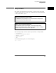


Table Of Contents
- Contents
- Title Page
- Chapter 1 Introduction to Programming
- Chapter 2 Programming Getting Started
- Chapter 3 Programming over HP-IB
- Chapter 4 Programming over RS-232-C
- Chapter 5 Programming and Documentation Conventions
- Chapter 6 Status Reporting
- Figure 6-1. Status Reporting Overview Block Diagram
- Table 6-1. Status Reporting Bit Definition
- Status Reporting Data Structures
- Status Byte Register (SBR)
- Service Request Enable Register (SRER)
- Trigger Event Register (TRG)
- Standard Event Status Register (SESR)
- Standard Event Status Enable Register (SESER)
- User Event Register (UER)
- Local Event Register (LCL)
- Operation Status Register (OPR)
- Limit Test Event Register (LTER)
- Mask Test Event Register (MTER)
- Histogram Event Register (HER)
- Arm Event Register (ARM)
- Error Queue
- Output Queue
- Message Queue
- Key Queue
- Clearing Registers and Queues
- Figure 6-3. Status Reporting Decision Chart
- Chapter 7 Installing and Using the Programmer's Reference
- Chapter 8 Programmer’s Quick Reference
- Warranty
- Index

Definite-Length Block Response Data
Definite-length block response data allows any type of device-dependent data
to be transmitted over the system interface as a series of 8-bit binary data
bytes. This is particularly useful for sending large quantities of data or 8-bit
extended ASCII codes. The syntax is a pound sign ( # ) followed by a
non-zero digit representing the number of digits in the decimal integer. After
the non-zero digit is the decimal integer that states the number of 8-bit data
bytes being sent. This is followed by the actual data.
For example, for transmitting 4000 bytes of data, the syntax would be:
The “8” states the number of digits that follow, and “00004000” states the
number of bytes to be transmitted.
Figure 2-1
Programming Getting Started
Definite-Length Block Response Data
2-11