
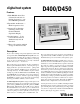
Instruction Manual

Isolates loop timing problems and verifies
stratum 2 clock synchronization. Improperly
synchronized networks experience occasional
frame slips which cause momentary disrup-
tions to channel data.
Description
Signaling Bits, Digits, Tones, Levels, Frequencies,
Alarms, any channel - all channels.
The Slip Counting feature allows the clock rates of
two T1 sources to be compared. Any differences
are counted and accumulated. This allows users to
determine if tariffed synchronization specifications
are being met. A simultaneous display of the T1
line frequency leaves no doubt as to the source of
trouble.
All 24 channels of signaling data can be displayed
simultaneously. Select the bits to be displayed in
both the East and West direction on two display
screens.
The D400 has a built-in tone synthesizer. Any tone
from 0 to 3990 Hz can be generated from +2.9 to
-60.0 dBm on all 24 voice channels. The receiver
section can measure the frequency and level of tones
over the same range.
Uses include: measuring loss, simulating
modem carrier tones, disabling echo
cancellers, responder tests.
In-Service testing of T1 or DLC, channel
by channel, card by card, bit by bit,
without service interruption.
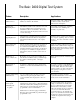
Feature
In-Service
Channel Access
Sending and
Measuring Tones
A,B,C,D
Signaling Bit Scan
Slip Counting and
Line Frequency
The Basic D400 Digital Test System
Applications
This allows users to monitor active channels
and compare signaling states in either
direction. Provides immediate activity
assessment.
Monitoring of voice or test tones in either one or
both directions simultaneously is possible through
the volume-controlled speaker or through a
headset.
In addition to displaying frequency and level, the
built-in tone receiver measures PCM offset on any
channel.
In properly operating systems, PCM offset
should be in the range of ±10 binary units
for voice traffic. Excessive offset could
indicate a faulty codec that could interfere
with signal processing devices such as
echo cancellers.
Allows direct assessment of channels at the
user level.
Measurement of
PCM Offset
Monitoring of
Voice or Test Tones
Activates or deactivates loopback features of
Channel Service Units (CSUs) or Network Interface
Units (NI or Smart jacks). Intelligent repeaters and
CSUs can be looped back through entering user
programmable codes for fault isolation.
Fault isolation on a T1 line equipped with Smart
Repeaters can be individually looped back through
programmable codes.
Any user defined 8 bit code can be sent on any
channel of a T1 span using this feature. The
received channel can be displayed in a 1/0 code
format.
To perform single-ended, out-of-service
testing of a T1 circuit, it is usually neces-
sary to loopback the far-end of a circuit.
Channel Service Units (CSUs) contain
built-in circuits that can detect a standard
code sent over the T1 link. The CSU
Loopback feature not only transmits the
proper codes, but indicates when the CSU
has attained loopback and reminds the user
to disable the loopback when testing is
complete.
This feature is useful for checking
loopback and maintenance codes on data
circuits, and in circuit identification.
CSU Loopback
NI Loopback
Smart Repeater
Loopback
Sending and Receiving
Channel Codes