
Parallel Port Input/Output Converter User Manual


PPIO2899 Manual
B&B Electronics Mfg Co Inc – 707 Dayton Rd - PO Box 1040 - Ottawa IL 61350 - Ph 815-433-5100 - Fax 815-433-5104
9
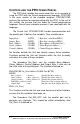
CONTROLLING THE PPIO USING GWBASIC
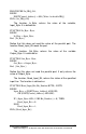
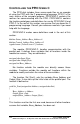
Refer to the fragment of GWBASIC code in Figure 2 to see how
to input the bits and make one 8-bit word.
100 OUT &H37A,&H04: REM This disables the 37AH Outputs
120 REM inside of the computer
140 REM so that we can use
160 REM 37AH as an input port.
180 REM It also disables
200 REM the IRQ7 interrupt.
.
.
300 A1=INP(&H37A) AND &H0F: REM Input the
320 REM lower 4 bits
340 REM and mask OFF
360 REM (force to 0)
380 REM the upper 4 bits.
400 A2=INP(&H379) AND &HF0: REM Input the high 4 bits
420 REM and mask OFF
440 REM the lower 4 bits.
460 IB=A1 OR A2 : REM This combines them
480 REM into one Input Byte.
.
.
Figure 2
The above assumes that you are using a parallel port located at
0378H. If you are using a different port you will have to replace the
hex addresses shown with the proper ones for your port. Refer also
to the PPIO.BAS program on the supplied disk for an example of
how to use GWBASIC to interface with the PPIO.
To output bits from the computer to the PPIO interface (still
using GWBASIC and the above 0378H example) use the following
line:
500 OUT &H378,OB
Where OB is the byte you want to output. If, for instance, you want
to turn ON (force LOW) PPIO bit 0, you must turn ON (force HIGH)
bit 1 of the variable OB. This can be done by ORing OB with &H01.
If you want to turn OFF (force HIGH or open) the same PPIO pin you
must turn OFF (force LOW) bit 1 of OB. Do this by ANDing OB with
NOT &H01. Use the data Table 2 to handle all eight PPIO bits.