-
NETWORK CAMERA / Operation Guide C VB-C500VD Y P O VB-C500D Be sure to read Start Guide and this Operation Guide before using the network camera.
-
Introduction Thank you for purchasing Canon Network Camera VB-C500VD/VB-C500D (hereafter referred to as VB-C500VD/VB-C500D.) This Operation Guide describes how to set up and use VB-C500VD/VB-C500D. Read these guides carefully before using VB-C500VD/VB-C500D to ensure that you make the best possible use of this product. Also, be sure to read the ReadMe file on the Setup CD-ROM. For the latest information on this product (firmware, bundled software, operation manuals, operating environment, etc.
-
Introduction Trademark Notice z Canon and the Canon logo are registered trademarks of Canon Inc. z Microsoft Windows and Microsoft Internet Explorer are trademarks or registered trademarks of Microsoft Corporation in the United States and other countries. z Windows is legally recognized as the Microsoft Windows Operating System. z Other brands or product names in this guide are trademarks or registered trademarks of their respective companies.
-
Introduction MPEG-4 NOTICE ABOUT THE MPEG-4 VISUAL STANDARD: THIS PRODUCT IS LICENSED UNDER THE MPEG-4 VISUAL PATENT PORTFOLIO LICENSE FOR THE PERSONALAND NON-COMMERCIAL USE OF A CONSUMER TO (i) ENCODING VIDEO IN COMPLIANCE WITH THE MPEG-4 VISUAL STANDARD ("MPEG-4 VIDEO") AND/OR (ii) DECODING MPEG-4 VIDEO THAT WAS ENCODED BY A CONSUMER ENGAGED IN A PERSONAL AND NON-COMMERCIAL ACTIVITY. NO LICENSE IS GRANTED OR SHALL BE IMPLIED FOR ANY OTHER USE.
-
Contents Introduction ..............................................................................................ii How to Read This Document ................................................................ viii Operation Manuals .......................................................................................... viii Icons Used in This Document ........................................................................... ix Top Page of the Camera ..............................................
-
Contents Chapter 2 VBAdmin Tools Overview of VBAdmin Tools ................................................................ 2-2 VBAdmin Tools ............................................................................................... 2-2 Motion Detection Setting Tool ........................................................................ 2-2 Log Viewer ..................................................................................................... 2-3 Admin Viewer ............................
-
Contents Chapter 4 Creating Web Pages for Video Distribution Web Pages for Video Distribution ........................................................ 4-2 Viewing Sample Pages ........................................................................ 4-4 Distributing Video Using VB Viewer ..................................................... 4-6 How to Create a Web Page Using VB Viewer ................................................ 4-6 Saving Web Page Data ..........................................
-
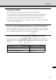
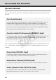
How to Read This Document Operation Manuals This camera comes with Start Guide, and Operation Guide (this document) included in Setup CD-ROM. Start Guide (Bundled) The safety precautions to be followed when using the VB-C500VD/VB-C500D, types of bundled software, operating environment, installation method, initial setting of the camera, etc., are explained. The Start Guide comes with the VB-C500VD/VB-C500D. In this manual, items that should be referenced in the Start Guide are described as follows.
-
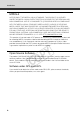
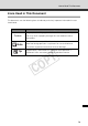
How to Read This Document Icons Used in This Document This document uses the following icons to indicate particularly important information the user should read. Icon Meaning Inappropriate handling against the instruction accompanied by this Caution icon may result in property damage. Be sure to observe these precautions. An important item or prohibited item that should always be Note observed during operation is explained. Be sure to read these instructions to prevent mechanical failure or damage.
-
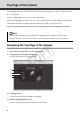
Top Page of the Camera The top page of the VB-C500VD/VB-C500D showing the setting menu, VB-C500 Viewer display, etc., is explained. Access the top page of the camera in the web browser. From the top page of the camera, you can access VB-C500 Viewer for displaying video and the Setting Menu that lets you specify detailed settings of the VB-C500VD/VB-C500D. If you are accessing the camera for the first time, see the Start Guide bundled with the camera.
-
Top Page of the Camera (3) Sample Page Link Click this link to display sample pages of the camera. (4) VB-C500 Viewer Launch Link Clicking this link launches VB-C500 Viewer that displays the video captured with the camera in the web browser. VB-C500 Viewer consists of two viewers: [Admin Viewer] and [VB Viewer] ( P. 3-2). z Explanation of each link [Admin Viewer] Launches Admin Viewer. [VB Viewer] Launches VB Viewer.
-
Top Page of the Camera Tip For specific ways in which you can utilize the sample pages, see "Chapter 4 Creating Web Pages for Video Distribution" ( P. 4-2). Accessing VB-C500 Viewer Select [Admin Viewer] or [VB Viewer] from the (4) [VB-C500 Viewer] links to access VB-C500 Viewer.
-
Top Page of the Camera User Authentication when Accessing the Setting Menu or Admin Viewer User authentication is required when accessing the camera's [Setting Menu] or [Admin Viewer]. Authentication Screen on Authentication Screen on [Setting Page] [Admin Viewer] The factory settings are specified below. User name: root Password: camera C Y P O The user name "root" is the Administrator account for the camera.
-
Top Page of the Camera Note z If the Administrator and authorized user are sharing VB-C500 Viewer on the same PC, it is strongly recommended that the [Remember my password] check box be cleared. z If a wrong user name or password is entered, the camera cannot be connected. Connect the camera by entering the correct user name and password. z If you have forgotten the Administrator password, press the reset switch to initialize the settings. See "Initializing with the Reset Switch on the Camera" ( P. 5-21).
-
Y P O Detailed Settings C The following explains the detailed settings on network connection, camera control, date & time, access control, etc.
-
Setting Menu You can move to each setting page from the Setting Menu to set various items regarding the camera. Items that can be set on each setting page are explained below. See each reference page for details. z Setting Menu z Network C Y P O Set the Administrator password, LAN, IPv6, DNS and SNMP ( P. 1-7). z Date and Time Set the date & time and time zone of the camera ( P. 1-12).
-
Setting Menu z Event Set the image buffer, motion detection, external device input, interval timer and audio file upload ( P. 1-32). 1 Detailed Settings z Access Control Set the authorized user accounts, user privileges and host access restriction ( P. 1-37). z IPsec Set IPsec ( P. 1-41). z Reboot Items "Setting the Items Requiring Rebooting (Reboot Item)" ( P. 1-45) z Maintenance "Tool" (View Log Events, View Current Settings, Reboot, Restore Settings) ( P. 1-47).
-
Accessing the Setting Menu The various settings of the VB-C500VD/VB-C500D are specified by accessing the camera in the web browser. First, access the top page ( P. x). For entry of the user name and password, see "User Authentication when Accessing the Setting Menu or Admin Viewer" ( P. xiii). Setting Menu You can access each setting page and Admin Viewer from the Setting Menu. Window Title Tab Title Menu Title Setting Menu (1) Window Title C Y P O Displays the model name of the connected camera.
-
Accessing the Setting Menu Items Common to All Setting Pages 1 Application of Setting Changes the top right of the setting page turns blue. To make the new setting effective, click the [Apply] button. To restore the original setting, click the [Clear] button. Setting Changes Requiring Rebooting The items whose setting will become effective only after the camera is rebooted are accompanied by an orange icon.
-
Accessing the Setting Menu Returning to the Setting Menu To return to the Setting Menu from each setting page, click the [Settings menu] button on the top right of the setting page. Note z Be sure to change the settings of each camera within one setting page. z Do not move between setting pages using the [Back] and [Forward] buttons of the browser. The new settings may return to the original settings or unwanted setting changes may occur.
-
Setting the Administrator Password, LAN, IPv6, DNS, etc. (Network) 1 Detailed Settings You can set the following items. z Administrator Password Set the Administrator password. z LAN Set the IP address and other items needed to establish LAN connection. z IPv6 Set IPv6. z DNS Set the name server address, host name and DDNS. z SNMP Set the SNMP. Administrator Password C Y P O (1) [Password] Set the Administrator password.
-
Setting the Administrator Password, LAN, IPv6, DNS, etc. (Network) LAN (1) [IP Address Setting] Select [Auto (DHCP)] or [Manual] as the address setting mode. If [Auto (DHCP)] is selected, the values automatically acquired from the DHCP server will be entered in [IP Address], [Subnet Mask] and [Default Gateway Address]. If [Manual] is selected, directly enter the values appropriate for the environment in which the camera is used.
-
Setting the Administrator Password, LAN, IPv6, DNS, etc. (Network) Note 1 z For [IP Address], [Subnet Mask] and [Default Gateway Address], contact your network z If any of the [IP Address], [Subnet Mask] and [Default Gateway Address] settings is wrong, network access may be disabled. In this case, use VB Initial Setting Tool Ver. 5.0.1 to set the address again. See "Perform Initial Setting of the Camera" ( Start Guide).
-
Setting the Administrator Password, LAN, IPv6, DNS, etc. (Network) DNS (1) [Name Server Address 1], [Name Server Address 2] Enter each name server address you want to register. If only one address is registered, keep the [Name Server Address 2] field blank. (2) [Host Name Registration with DDNS] Select [Enable] and enter the host name. The host name can be registered in the name server. You can use up to 63 (single-byte) characters including A to Z, a to z, 0 to 9, "-" (hyphen), "_" (underber) and ".
-
Setting the Administrator Password, LAN, IPv6, DNS, etc. (Network) (4) [Administration Function Name] Set the camera name used for administration. The set name can be referenced by the SNMP Manager. 1 If this field is left blank, "VB-C500VD" is used by default when the connected camera is Detailed Settings VB-C500VD, and "VB-C500D" when the connected camera is VB-C500D. (5) [Installation Location] Set information regarding the installation location of this camera.
-
Setting the Date and Time (Date and Time) You can set the following items. z Current Date and Time The date and time set in the camera is shown. z Setting Select the date & time setting method and time zone for this camera. Current Date and Time [Date], [Time] Y P O The date and time currently set in the camera is shown. Setting C (1) [Setting Method] Select [Set manually], [Synchronize with NTP server], [Synchronize with NTP broadcast] or [Synchronize with computer time].
-
Setting the Date and Time (Date and Time) Example: To specify August 23, 2008 1:23:04 pm, enter "2008/08/23" and "13:23:04." 1 The camera will synchronize with that time of the NTP server. Enter the IP address of the NTP server. [Synchronize with NTP broadcast] Y P O The camera will synchronize with the NTP broadcast time. C [Synchronize with computer time] The camera will synchronize with the date and time of the computer currently accessing the camera.
-
Setting the Camera Control and External Device Name (Camera) You can set the following items. z Camera Name Enter the name of the camera. The camera name is require if VK-64, etc., is used with the camera. z Initial Camera Settings Set the AF Mode, Slow Shutter and Shutter Speed. z Camera Control Set the digital zoom. z Day/Night Set the Day/Night switching mode. z Installation Conditions Set the image flip.
-
Setting the Camera Control and External Device Name (Camera) Initial Camera Settings 1 Detailed Settings [AE Mode], [Slow Shutter], [Shutter Speed] Set the camera exposure control and shutter speed. [AE Mode] [Auto] The exposure is controlled automatically. [Flickerless] In this mode, image flickers caused by fluorescent lights, etc., can be reduced. The shutter speed is automatically adjusted according to the brightness of the environment in which the camera is used.
-
Setting the Camera Control and External Device Name (Camera) Camera Control [Digital Zoom] Select [Enable] or [Disable] for digital zoom. * The higher the digital zoom ratio, the lower the image quality becomes. Day/Night (1) [Mode] Y P O Select [Manual] or [Auto] as the Day/Night mode. If [Manual] is selected, you can manually switch [Day Mode] and [Night Mode] using the Admin Viewer Night Mode function ( P. 3-28). If [Auto] is selected, set [Switching Brightness] and [Response (sec.
-
Setting the Camera Control and External Device Name (Camera) Note z If you want to set [Auto] for [Day/Night], conduct a thorough operation test and check the z If [Auto] is selected under [Day/Night], set [Auto], [ Auto (Flickerless)], or [Auto (Shutterpriority AE)] under [Exposure] on VB-C500 Viewer ( P. 3-23). z If [Night Mode] is selected, image does not become brighter even when infrared lamp is used.
-
Setting the Image Size, Quality, Frame Rate, On-Screen Display of Date and Time, etc. (Video) You can set the following items. z JPEG Set the image quality, size and maximum frame rate in JPEG. z MPEG-4 Set the video quality, size and capture frame rate in MPEG-4. z On-screen display Set the on-screen display of date and time or text strings on the image. JPEG C Y P O (1) [Image Quality] Select a desired quality from 1 to 5 (total 5 levels) for image transmitted at each image size in JPEG.
-
Setting the Image Size, Quality, Frame Rate, On-Screen Display of Date and Time, etc. (Video) MPEG-4 1 Detailed Settings (1) [Video Quality] Select a desired quality from 1 to 5 (total 5 levels) for video transmitted in MPEG-4. The greater the value, the higher the quality becomes. (2) [Video size] Select [320 x 240] or [640 x 480] for the size of video transmitted. (3) [Capture Frame Rate] Select [10], [15] or [30] (fps) as the capture frame rate.
-
Setting the Image Size, Quality, Frame Rate, On-Screen Display of Date and Time, etc. (Video) On-Screen Display (1) [Date display] Select whether or not to display the date on the image. Date information is superimposed on the image when [Enable] is selected. (2) [Position of date display] Y P O Select the position to display date information from [Upper left], [Upper right], [Lower left], or [Lower right].
-
Setting the Image Size, Quality, Frame Rate, On-Screen Display of Date and Time, etc. (Video) (7) [Position of text display] Select the position to display the text string from [Upper left], [Upper right], [Lower left], or [Lower right]. 1 Set a text string of 15 alphanumeric characters or less to superimpose on the image when (6) [Text display] is set to [Display designated string].
-
Setting HTTP/FTP Upload and E-mail Notification (Upload) You can set the following items. z General Upload Set the upload operations. z HTTP Upload Set the upload via HTTP connection. z FTP Upload Set the upload via FTP connection. z E-mail Notification Set items relating to sending of event information and video by e-mail. General Upload [Upload] C Y P O Select [Upload Disabled], [HTTP Upload] or [FTP Upload] as the upload mode.
-
Setting HTTP/FTP Upload and E-mail Notification (Upload) z Reduce the uploading frequency: - Reduce the value in [Pre-event Buffer (number of image frames)] or [Post-event Buffer (number of image frames)] ( P. 1-32). 1 - If [Motion Detection Event] is enabled, disable [ON Event Operation], [OFF Event - If [External Device Input Event] is enabled, disable [ON Event Operation or [OFF Event Operation] ( P. 1-34). - If [Interval Timer Event] is enabled, increase the value in [Interval of the Timer] ( P.
-
Setting HTTP/FTP Upload and E-mail Notification (Upload) (5) [Proxy Port] Enter the port number of the proxy server (default = [80]). (6) [Proxy User Name], [Proxy Password] Enter the user name and password of the proxy server. (7) [Parameter (query string)] Enter an appropriate parameter (using up to 127 characters). The parameter can be entered using "%" characters ( P. 5-2). (8) [HTTP Upload Test] Clicking the [Exec] button initiates an upload test based on the settings currently applied.
-
Setting HTTP/FTP Upload and E-mail Notification (Upload) (6) [File Naming] Set a desired file naming mode. [YYMMDDHHMMSSms] 1 Image is uploaded according to the file name format of [YYMMDD Directory/HHMMSSms] A subdirectory named "{year}{month}{day}" is created first, and then the image is uploaded using the file name "{hour}{minute}{second}{ms}.jpg." (Example: 20080123/112122000.jpg) [Loop] Image is updated under a file name consisting of a number up to the value set in [Maximum Number of Loops].
-
Setting HTTP/FTP Upload and E-mail Notification (Upload) E-mail Notification (1) [Notification] Select [Text only] or [Text with image] as the content of notification. (2) [Mail Server Name] Y P O Enter the host name or IP address of the SMTP server (using up to 63 characters). (3) [Mail Server Port] Enter the port number of the SMTP server (default = [25]). (4) [Sender (From)] C Set the e-mail address of the sender (using up to 63 characters).
-
Setting HTTP/FTP Upload and E-mail Notification (Upload) (6) [Authentication] Select [None], [POP before SMTP] or [SMTP-AUTH] as the e-mail authentication mode. Set an appropriate mode according to the authentication mode used by the SMTP server to send to. If [POP before SMTP] is selected as the e-mail authentication mode, enter the user name, password, and host name or IP address of the POP server, required for authentication.
-
Setting the Image Server, Audio Server and HTTP Server (Server) You can set the following items. z Image Server Set the items needed to deliver image from the camera. z Audio Server Set the items relating to transmitting/receiving audio. z HTTP Server Set the HTTP port and web page delivery. Image Server (1) [Maximum Number of Clients] C Y P O Set the maximum number of clients that can be connected to the camera at the same time. Up to 30 clients can be set.
-
Setting the Image Server, Audio Server and HTTP Server (Server) Audio Server 1 Detailed Settings (1) [Audio Transmission from the Camera] When [Enable] is selected, the audio input through the microphone attached to the camera can be transmitted to VB-C500 Viewer. (2) [Input Volume] Set the volume of input sound in a range of 1 to 100. The greater the value, the larger the input volume becomes.
-
Setting the Image Server, Audio Server and HTTP Server (Server) Audio Transmission Input Volume Voice Activity Detection Echo Canceller LAN Audio Reception Output Volume LAN Y P O Caution Switch [Line In] and [Microphone In] on each setting page according to the specification of the microphone ( P. 1-29). C If a wrong input is used, the camera or microphone may be damaged. Be sure to set the correct input. Note z The volume, sound quality, etc.
-
Setting the Image Server, Audio Server and HTTP Server (Server) HTTP Server 1 Detailed Settings (1) [HTTP Port] Set the HTTP port number in a range of 80 and 1024 to 65535. Normally [80](factory setting) should be used. (2) [Global Address for the Web Page] If a fixed global address is assigned to the camera using the NAT function of the router ( P. 4-12), set the global address and port number here. If [IP Address] is selected, enter the specified IP address in the [IP Address] field.
-
Setting the Image Buffer, Motion Detection, Audio Playback and Interval Timer (Event) You can set the following items. z Image Buffer Set the items associated with the temporary saving of image in the image buffer. z Motion Detection Set the operation to be performed at the time of motion detection. z External Device Input Set the operation to be performed when an event is input from an external device. z Interval Timer Set the timer period for e-mail notification or upload.
-
Setting the Image Buffer, Motion Detection, Audio Playback and Interval Timer (Event) Motion Detection 1 Detailed Settings (1) [Motion Detection Event] Whether motion detection events are enabled/disabled is shown. The value of this item can be changed using Motion Detection Setting Tool in VBAdmin Tools ( P. 2-7). When motion Y P O detection events are enabled, event notification to the viewer is performed according to the displayed motion detection event of this camera such as Admin Viewer.
-
Setting the Image Buffer, Motion Detection, Audio Playback and Interval Timer (Event) (7) [Audio Playback at ON Event] Select the audio playback operation to be performed upon an ON event. If [Enable] is selected, the sound specified under [Sound Clip] will be played when the mode changes to [Detected] (ON event). (8) [Audio Playback at OFF Event] Select the audio playback operation to be performed upon an OFF event.
-
Setting the Image Buffer, Motion Detection, Audio Playback and Interval Timer (Event) (2) [ON Event Operation] Select the operation to be performed upon an ON event. If [Enable] is selected, (4), "Upload," (5) and "E-mail Notification" are displayed. When an ON input is received from an external device (ON event), the processes set in (4) and (5) are performed. Select the operation to be performed upon an OFF event. If [Enable] is selected, (4), "Upload," (5) and "E-mail Notification" are displayed.
-
Setting the Image Buffer, Motion Detection, Audio Playback and Interval Timer (Event) Interval Timer (1) [Interval Timer Event] Select whether to [Enable] or [Disable] timer events.If [Enable] is selected, (2), "Timer Interval," (3), "Upload" and (4), "E-mail Notification" are displayed. (2) [Interval of the Timer] Select a desired timer interval from the pull-down menu in a range of [1 sec.] to [24 hours]. (3) [Upload] Select the upload operation.
-
Setting User Access Privileges (Access Control) 1 Detailed Settings You can set the following items. z Authorized User Account Register users who can access this camera. z User Authority Set the privileges of authorized users and guest users. z Host Access Control Specify the hosts from which access is permit and restricted. Authorized User Account (1) [User Name], [Password] C Y P O Enter the user name and password and then click [Add]. The authorized user will be added to the user list.
-
Setting User Access Privileges (Access Control) User Authority [Privileged Camera Control], [Camera Control], [Image Distribution], [Audio Distribution] Set the user privileges of authorized users and guest users. Select the check boxes corresponding to the items you want to permit for each user. Tip Authorized users can have higher privileges than guest users. Host Access Restriction C Y P O (1) [Host List] A list of hosts from which access is permitted and restricted is shown.
-
Setting User Access Privileges (Access Control) Note z If no host list is available, access is permitted to all hosts. disabled and access is permitted to all hosts. z To prohibit access via a proxy server in HTTP connection, a proxy server address must be set. z If Host Access Restriction is set wrongly, access to the setting pages itself may be prohibited, in which case restoring the factory settings will become the only means for recovery.
-
Setting User Access Privileges (Access Control) Example of description Example 1. Prohibit access from a given access !172.20.0.10 Access from the host whose address is 172.20.0.10 is prohibited. Example 2. Prohibit access from hosts in a given range !172.20.0.0-172.20.0.20 Access from the hosts whose address is in a range of 172.20.0.0 to 172.20.0.20 is prohibited. Example 3. Permit access from hosts in a given range and prohibit access from all other hosts 172.20.0.10-172.20.0.12 !0.0.0.0-255.255.255.
-
IPsec Settings (IPsec) 1 You can set the following items. IPsec Set IPsec Sets 1 to 5 are available, where IPsec settings for each communication using each IPsec Set. (1) [IPsec] Y P O Select [Manual] if IPsec will be used. Select [Disable] if IPsec will not be used. (2) [IPsec Mode] C Select [Tunnel Mode] or [Transport Mode] as the IPsec operation mode. (3) [Destination Address (IPv4/IPv6)] Enter the IP address of the connection destination.
-
IPsec Settings (IPsec) If [ESP] or [ESP and AH] was set under [Security Protocol] in (5), the following items must be set. (8) [SA ESP Encryption Algorithm] Y P O Select [AES], [3DES], [DES] or [NULL] as the ESP encryption algorithm according to the encryption algorithm supported by the device to connect to. Normally [AES] or [3DES] is recommended.
-
IPsec Settings (IPsec) (14) [SA ESP Authentication key (inbound)] Set the SA authentication key for inbound. If [HMAC_SHA1_96] or [HMAC_MD5_96] was set in (9), set a 160-bit or 128-bit hexadecimal, respectively. This item need not be set if [No Authentication] was selected. Set the SA SPI value for inbound. Set a desired value in a range of 256 to 4294967295.
-
IPsec Settings (IPsec) (20) [SA AH SPI (inbound)] Set the SA SPI value for inbound. Set a desired value in a range of 256 to 4294967295. Since this setting is used as an ID for identifying the SA, be careful not to specify an inbound SPI whose value is already used the SPI for other AH. Note z To use this camera using IPsec, the communicating destinations and network must be set beforehand. For these settings, contact your System Administrator.
-
Setting the Items Requiring Rebooting (Reboot Item) 1 Detailed Settings The following items that require rebooting, if changed, are gathered here. z LAN, IPv6, Installation Conditions, MPEG-4, HTTP Server (1) [LAN] C Y P O IP address and other settings required for LAN Connection ( P. 1-8) (2) [IPv6] Settings relating to use of IPv6 ( P. 1-9) (3) [Installation Conditions] Settings relating to camera installation conditions ( P.
-
Setting the Items Requiring Rebooting (Reboot Item) Note These settings relate to network connection. If any setting is changed to a value that may disable camera connection from the active browser, the following dialog box is displayed to alert the user. To apply the new setting, click [OK]. Depending on the new setting, it may not be possible to connect to the camera again after rebooting.
-
Viewing Event Logs and Current Settings, and Performing Maintenance (Maintenance) Viewing Event Logs and Current Settings, and Performing Maintenance (Maintenance) 1 Detailed Settings The following items can be used here. z Tool Display and initialize the settings of the camera. Tool (1) [View Log Events] Y P O Historical data of the camera such as operations and connections with various viewers, etc., is shown. (2) [View Current Settings] C A list of current settings is shown.
-
Viewing Event Logs and Current Settings, and Performing Maintenance (Maintenance) C 1-48 Y P O
-
Y P O VBAdmin Tools C How to set the camera using VBAdmin Tools is explained. You can set the motion detection, view logs, and start Admin Viewer. Set each item after specifying the necessary detailed settings according to Chapter 1.
-
Overview of VBAdmin Tools VBAdmin Tools consists of multiple applications for [Motion Detection Setting Tool], [Log Viewer] and [Admin Viewer]. You can remotely set the camera, view privileged images, check the operating condition, acquire logs, and perform other operations with ease. VBAdmin Tools ( P. 2-4) This is the main panel for VBAdmin Tools. You can start each tool from this panel. First, install VBAdmin Tools. See "Install the Necessary Software" ( Start Guide).
-
Overview of VBAdmin Tools Log Viewer ( P. 2-18) This viewer shows view the logs of operating conditions output to the camera. VBAdmin Tools Admin Viewer ( P. 3-6) Y P O This viewer is used by the camera's Administrator. It provides privileged functions not available in VB Viewer, such as camera control, exposure, white balance and external device output. C Note Regardless of the settings under "Regional and Language Options" in the Windows Control Panel, a ".
-
Launching VBAdmin Tools How to Launch 1. Double-click the [VBAdmin Tools v5.1] icon on the desktop, or click the [Start] menu, click [Programs], click [WebView Livescope], and then select [VBAdmin Tools v5.1]. Starting from the Desktop Icon Or starting from the [Start] menu 2. The dialog box for specifying the camera to connect to appears. To use VBAdmin Tools, you must connect to the camera first. Enter each item and then click [OK]. (1) (2) (3) Y P O (4) (5) C (6) (7) (1)Host name ( P. 1-8, P.
-
Launching VBAdmin Tools (6)Proxy * For the proxy settings, check with your Network Administrator. • [Use HTTP proxy server] Select this check box to connect to the camera via a proxy server. • [Host name] Specify the host name or IP address of the proxy server. Enter the port number of the proxy server (default = [8080]). • [Load proxy information] When this button is clicked, the proxy server information set by Internet Explorer will be imported automatically. (7)FTP Not used with this camera.
-
Launching VBAdmin Tools If the connection has been cut off, etc., select [Connect] from [File] in the menu bar to open the [Connection settings] dialog box. Note Notes on Use with Windows Vista/XP If the [Windows Security Alert] dialog box appeared, click [Unblock]. Once this button is clicked, this warning dialog box will no longer appear. Note If connection is made by entering the IPv6 address, Admin Viewer cannot be used on Internet Explorer 6.
-
Motion Detection Setting Tool This tool is used to set the motion detection function that performs upload, notifies the viewer, records a log, etc., if a change has occurred in the captured image due to movement of a subject. You can set the position and size of the motion detection area, detection judgment conditions, etc., while checking the image on the camera. VBAdmin Tools You can set the Motion Detection function with ease using Motion Detection Setting Tool.
-
Motion Detection Setting Tool Display Screen of Motion Detection Setting Tool (Live Mode) (1)(2) (3) (4) (8) (9) (5) (6) (7) C (1) [Load Motion Detection Settings] button Y P O (10) Clicking this button loads the current motion detection settings of the camera. (2) [Save Motion Detection Settings] button Clicking this button saves the motion detection setting edited by this tool. If you have set motion detection, be sure to save the settings using [Save Motion Detection Settings].
-
Motion Detection Setting Tool (6) Motion detection area frame The range in which motion detection is performed is shown by a dotted-line frame. You can drag the mouse to resize/move the frame. (7) [Start recording] button Clicking this button starts recording video. (8) [Enable motion detection of the camera] VBAdmin Tools Select this check box if you want to enable the motion detection function. (9) Settings tabs (Camera/Area) • [Camera] Set the frame rate ( P. 2-10).
-
Motion Detection Setting Tool 5. Save the settings. Tip z The Motion Detection Setting Tool viewer window shows 160 x 120 black & white image regardless of the camera settings. z In the [Area] tab, you can set the [Detected] judgment conditions for each area while checking the viewer image on the left side of the screen. For the applicable display screen, etc., see "[Detected] Mode and Display Screen" ( P. 2-14).
-
Motion Detection Setting Tool Note The value set in [Maximum Frame Rate: Image Transmission] ( P. 1-18) must be greater than the frame rate set by this tool. z If the network load is heavy, the specified frame rate may not be achieved. z By setting a lower frame rate, the video extracted from the captured video will be included in the scope of motion detection. This way, you can also perform motion detection for slow-moving subjects, etc. z The frame rate set here is applied only to motion detection. 3.
-
Motion Detection Setting Tool (2)[Selected Area] If multiple motion detection area frames have been created, a separate motion detection level can be set for each area frame. Set the area name for the selected area below. (Area name can also be omitted.) Up to 15 ASCII characters (spaces or printable characters) can be used for the [Area name]. (3)[Sensitivity] Set the sensitivity of motion detection in a range of 1 to 256. Set a desired value by dragging the slide bar.
-
Motion Detection Setting Tool (8)[Details] When this check box is selected, you can enter [Sensitivity], [Size] and [Duration] values. If the check box is not selected, [Duration (sec.)] is fixed to [0.2]. Tip z Even when a change has occurred in the image shown inside the viewer's motion detection area frame, the camera will not recognize it as [Motion] if the [Sensitivity] setting is low. the part of the area frame that has moved meets the [Size] and [Duration] settings for motion.
-
Motion Detection Setting Tool Tip z The status of the detection in peak block view and [Display motion detection status of the camera] in this tool may not match the actual motion detection status of the camera. z When the motion detection function of the camera is enabled, the video frame rate may drop compared to when the function is disabled.
-
Motion Detection Setting Tool If a change occurred in the image, the value set in [Size] is shown by a vertical bar on the indicator. The following two indicator colors are used. Green : The area of the motion detected by the camera does not meet Yellow : The area of the motion detected by the camera meets [Size]. Peak block A red peak block will be displayed when both the [Size] and [Duration] conditions are satisfied and the camera mode changes to [Detected].
-
Motion Detection Setting Tool Tip Setting the Motion Detection Sensitivity While Checking the Recorded Video To set the motion detection level at which the camera mode will change to [Detected], you can adjust the settings while checking the actual motion in the viewer. The camera lets you set a desired motion detection level while playing the live video recorded in the Live tab ( P. 2-8), so you need not repeat the actual motion in front of the camera.
-
Motion Detection Setting Tool 3. Adjust the motion detection sensitivity in the [Area] tab while checking the video in the [Video] tab. VBAdmin Tools (2) (3) (1) Y P O (4) (1)List of recorded video C A list of recorded video is shown. (2)[Delete] button Clicking this button deletes the video selected from the list of recorded videos. (3)[Delete All] button Clicking this button deletes all videos shown in the list of recorded videos.
-
Log Viewer This viewer lets you view the operating condition log of the camera. Tip z Log Viewer only has a log viewing function and logs cannot be deleted. z Logs are saved by selecting [Save] from [File] in the menu bar. Logs can be saved in the text format. Downloading Log Files How to Download Y P O Launch Log Viewer from VBAdmin Tools, and the latest log files will be downloaded and C displayed automatically. To download a new log file list, select [Download] from [File] in the menu bar.
-
Log Viewer Viewing Logs The log contains the following information. z Code The log code is shown. For the log code, see "List of Log Messages" ( P. 5-7). If the log has no log code, no icon is shown. Information level Error level Warning level z Date and Time The date and time at which the log was generated is shown. z Message A message regarding the log is shown. Y P O Saving a Log to a File/Opening a Saved Log C You can save the displayed log to a file or view a log file saved before.
-
Log Viewer Copying/Searching Logs You can copy the displayed log or search logs. How to Copy Click to select the log you want to copy, and then select [Copy] from [Edit] in the menu bar. How to Search 1. Select [Search] from [Edit] in the menu bar. The Search dialog box appears. C Y P O 2. Enter a desired character string, and then click [Search]. Showing All Logs How to Display Select [Show all logs] from [View] in the menu bar.
-
Log Viewer Showing Filtered Logs You can filter logs by type, code and date & time to show only the necessary information. How to Set 1. Select [Filter] from [View] in the menu bar. VBAdmin Tools 2. The Filter dialog box appears. Setting the following conditions and clicking [OK] shows only the logs matching the specified conditions. To cancel filtering, click [Cancel]. [Log type] C Y P O Select the [Specify type] or [Specify code] check box to filter logs by type.
-
Log Viewer [Date and Time] z [Specify start date & time] When this check box is selected and a date and time is entered, logs generated on or after the specified date and time are displayed. z [Specify end date & time] When this check box is selected and a date and time is entered, logs generated on or before the specified date and time are displayed. Tip [Application], [HTTP Server] and [System] support the log message list ( P. 5-7).
-
Y P O VB-C500 Viewer C The following explains VB-C500 Viewer that lets you access the camera using a web browser to display live video, zoom of the camera, control the exposure, control the night mode, adjust the white balance, and control the smart shade control function, among others.
-
Overview of VB-C500 Viewer VB-C500 Viewer is a viewer that lets you access the network camera VB-C500VD/VB-C500D via a web browser to display image and operate the camera via zoom control, etc. Two types of viewers, Admin Viewer and VB Viewer, are available for VB-C500 Viewer. VB-C500 Viewer Admin Viewer Note C VB Viewer Y P O Use VK-Lite Viewer to display MPEG-4 video from the camera. Only JPEG video can be displayed using the built-in VB-C500 Viewer.
-
Overview of VB-C500 Viewer User Authorities and Camera Control Privileges The relationships of user authorities and camera control privileges are specified below.
-
Overview of VB-C500 Viewer [Guest User] This user can only perform zoom controls of the camera, backlight compensation, video display and audio distribution. The guest user can launch VB Viewer from the [VB Viewer] link on the top page. The Administrator can prevent all camera accesses by a guest user by disabling all authorities of the user. Note z Admin Viewer launched by an [Administrator] can take over the camera control privileges from Admin Viewer launched by an [Authorized User] at any time.
-
Overview of VB-C500 Viewer Tip z The factory setting is to also give the Privileged Camera Control to [Authorized User]. z If all authorities of a guest user are disabled, the user authentication dialog box will appear when the user launches VB Viewer. When an authorized user or Administrator name and password are entered, a guest user can use VB Viewer based on the authorized user or Administrator authorities.
-
Launching VB-C500 Viewer Launching VB-C500 Viewer The various settings of VB-C500 Viewer are specified by accessing the camera via a web browser. First, access the Settings title page. Note This document explains relevant operations based on the IP address "192.168.100.1" (factory setting). In reality, the customer must enter the IP address set for the camera. How to Launch 1. Access "http://192.168.100.1/" in the web browser. 2. Click [Admin Viewer] or [VB Viewer] according to the user. C Y P O 3.
-
Launching VB-C500 Viewer 4. VB-C500 Viewer launches. VB-C500 Viewer Shutting Down VB-C500 Viewer How to Shut Down Close the web browser in the viewer to shut down. Y P O Connecting from VBAdmin Tools Only the Administrator can connect to this viewer. How to Launch 1. Launch VBAdmin Tools. C For information on how to launch VBAdmin Tools, see "Launching VBAdmin Tools" ( P. 2-4) in "Chapter 2 VBAdmin Tools". 2. Click [Admin Viewer].
-
Launching VB-C500 Viewer 3. Enter the user name and password. The factory settings are as follows ( P. xiii) : User name: root Password: camera The user name "root" is the Administrator account for the camera. * The password is "camera." Be sure to change them on the [Network] setting page ( P. 1-7). 4. Admin Viewer launches in the web browser. Note C Y P O If a wrong user name or password is entered, the camera cannot be connected. Connect the camera by entering the correct user name and password.
-
How to Operate VB-C500 Viewer Display Screens of Admin Viewer The following gives an overview of the functions of buttons, boxes and other screen elements displayed when Admin Viewer is launched. (1) (2) (3) (4) (5) (6) (13) (14) (15) VB-C500 Viewer (16) (7) (17) (8) (9) (10) (11) (12) (18) (23) (22) C Y P O (20) (19) (21) (1) Video Capture Size Set the size of video received from the camera. (2) Video Display Size Set the display size of video shown on the screen.
-
How to Operate VB-C500 Viewer (6) Audio Reception button Audio from the camera is received and output. (7) On-screen display Items set to [Enable] in [On-screen display] under [Video] on the Setting page are displayed in the specified position ( P. 1-20). (8) Scroll bar for zoom This scroll bar is used to control the zoom ratio. You can zoom in (show a telephoto view) by moving the knob upward or zoom out (show a wide-angle view) by moving the knob downward.
-
How to Operate VB-C500 Viewer (20) [White Balance] You can control the white balance. (21) [Motion Detection] The status of motion detection is shown. (22) [Smart Shade Control] You can operate the Smart Shade Control. (23) [Night Mode] Display Screens of VB Viewer The following gives an overview of the functions of buttons, boxes and other screen elements displayed when VB Viewer is launched.
-
How to Operate VB-C500 Viewer (5) Audio Reception button Audio from the camera is received and output. (6) On-screen display Items set to [Enable] in [On-screen display] under [Video] on the Setting Menu are displayed in the specified position ( P. 1-20). (7) Zoom Controller This bar is used to control the zoom ratio. (8) [Backlight Compensation] button This button turns on/off backlight compensation. This control is effective when the image is dark due to backlight.
-
How to Operate VB-C500 Viewer Obtaining the Camera Control Privilege The camera cannot be controlled by multiple users at the same time. Only the user with the control privileges can control the camera. To perform zoom operations, implement backlight compensation or otherwise control the camera, you must obtain the control privileges first. How to Operate Click "Obtain/release Camera Control" button to obtain the control privileges.
-
How to Operate VB-C500 Viewer Changing the Camera Zoom Ratio How to Operate Admin Viewer Move the knob on the scroll bar for zoom in/out. The camera zoom ratio will change according to the knob position on the scroll bar. You can also move the knob by clicking a blank point on the scroll bar. Zoom telephoto end Scroll bar for zoom Move the knob upward to zoom in (show a telephoto view), or move it downward to zoom out (show a wide-angle view).
-
How to Operate VB-C500 Viewer Compensating Backlight This control is effective when the image is dark due to backlight. How to Operate Clicking [Backlight Compensation] brightens the image that was previously dark due to backlight. Clicking the button again cancels backlight compensation.
-
How to Operate VB-C500 Viewer Changing the Video Capture Size You can set a desired resolution for video received from the camera. Select from [160x120], [320x240] and [640x480]. Changing the Video Display Screen You can change the video display screen. Select from [160x120], [320x240] and [640x480]. Tip Y P O z When the viewer is launched, the video capture size set for the camera is applied ( P. 1-18). C z When the viewer is launched, the video display size becomes [320x240].
-
How to Operate VB-C500 Viewer Saving the Paused Image How to Operate 1. Click the "Pause/Resume" button to pause video. 2. Bring the cursor over the video screen and right-click the mouse to display the pop-up menu. VB-C500 Viewer 3. Select [Save Picture As]. 4. Enter a file name and save the image. Y P O * Although the sample screen is that of Admin Viewer, you can also save the image in VB Viewer using the same operation.
-
How to Operate VB-C500 Viewer Receiving Audio You can receive audio through the microphone attached to the camera. Click this button to receive audio. Tip z To receive audio, set [Enable] for [Audio Transmission from the Camera] under [Audio Server] of [Server] on the setting page beforehand ( P. 1-29). z Audio cannot be received if you are using a proxy server. Displaying Information Y P O Viewer information, warning messages, etc., are shown.
-
How to Operate VB-C500 Viewer Warning Message A warning message is indicated by a yellow icon. If an unsupported web browser is used or audio reception stops, a message will be displayed to alert the user. Error Message VB-C500 Viewer An error message is indicated by an orange icon. An error message will be displayed if the viewer generates an error. Tip Y P O For details on the above messages, see "List of VB-C500 Viewer Messages" ( P. 5-17).
-
Performing Operations and Settings as the Administrator The operations and settings that can only be performed in the Admin Viewer are explained. Opening Control for Admin Panel How to Operate 1. Click "Obtain/release Camera Control" button to obtain the control privileges. 2. Click [Control for Admin]. C Y P O 3. The Control for Admin panel appears.
-
Performing Operations and Settings as the Administrator Operating the External Device Output You can operate the external device output and display the current output status using an icon. The [ON]/[OFF] status can be switched by clicking this icon. VB-C500 Viewer Example: Top: Output OFF Bottom: Output ON Y P O Displaying the External Device Input Status C You can check the status of external device input and display it using an icon.
-
Performing Operations and Settings as the Administrator Displaying the Motion Detection Status You can display the detection status of the motion detection function. Example: Areas 1 to 3: Detection status OFF Area 4: Detection status ON Tip Y P O Set the motion detection options beforehand using "Motion Detection Setting Tool" of VBAdmin Tools ( P. 2-7). Controlling/Setting the Camera C Click the applicable camera control buttons to perform zoom operation and set the speed of each operation.
-
Performing Operations and Settings as the Administrator (2) [Zoom] speed Select a desired operation speed from [Fast] and [Slow]. Tip Even when the [Zoom] speed setting is changed, the speed of zoom operation performed using the scroll bar will not change. Setting the Exposure VB-C500 Viewer You can set various options relating to exposure operation. C Y P O (1) (2) (3) (4) (5) (1) Exposure Mode Select [Auto], [Manual], [Auto (Flickerless)] or [Auto (Shutter-priority)].
-
Performing Operations and Settings as the Administrator (3) Metering Mode When [Auto], [Auto (Flickerless)] or [Auto (Shutter-priority)] is selected as the exposure mode, select a desired metering mode from [Center-Weighted], [Average] and [Spot]. [Center-Weighted] The entire screen is metered by focusing on the center of the screen. Even when slightly darker/brighter areas are present on the periphery of the screen, an appropriate exposure can be achieved for the subject near the center.
-
Performing Operations and Settings as the Administrator Setting the White Balance Select a desired white balance setting from [Auto], [Light Source] and [Lock]. (1) (2) VB-C500 Viewer (1) [Auto] The white balance is adjusted automatically. (2) [Light Source] Select the light source from the pull-down menu below according to the condition in which the camera is used. [Daylight Fluorescent] Y P O :Select this option to capture video under daylight fluorescent lighting.
-
Performing Operations and Settings as the Administrator (3) (3) [Lock] The white balance is fixed to that of the video currently received. To forcibly fix the white balance according to the light source, use [One-shot WB]. Example of setting method: Irradiate a white subject (white paper, etc.) using the light source and capture the subject over the entire screen. In this condition, select [One-shot WB].
-
Performing Operations and Settings as the Administrator Setting the Smart Shade Control Smart Shade Control is a function that, unlike the Backlight Compensation, brightens only dark areas while keeping bright areas intact. (1) (2) VB-C500 Viewer (1) Smart Shade Control Set [OFF] or [ON]. (2) Adjusting the Smart Shade Control When [On] is selected for Smart Shade Control, set one of seven control levels from [1] (weak) to [7] (strong).
-
Performing Operations and Settings as the Administrator Setting the Night Mode Switch between [Day Mode] and [Night Mode]. Tip The Night Mode cannot be used if [Auto] is set for Day/Night under [Camera] on the setting page ( P. 1-16). [Day Mode] Y P O Color image can be viewed in the normal mode. [Night Mode] C Images are shown in black & white.
-
Y P O Creating Web Pages for Video Distribution C This chapter explains how to distribute image using the VB-C500VD/VB-C500D. You can distribute image in various ways, such as displaying video or still images or showing multiple images on a Web page.
-
Web Pages for Video Distribution You must create a dedicated Web page to distribute information from the camera you have installed. "VB-C500 Viewer" can be used as the camera's viewer, where you can set detailed parameters.
-
Web Pages for Video Distribution Note The VB-C500VD/VB-C500D has a built-in Web server. Write desired content for the Web page for video distribution in the flash memory in the camera beforehand, and you can publish the Web page and distribute image over the Web using the camera alone. For information on how to save Web page data, see "How to Create a Web Page Using VB Viewer" ( P. 4-6).
-
Viewing Sample Pages This camera stores sample pages for video distribution. You can view the sample pages by following the procedure below. Use these samples as a reference when creating a Web page. How to View 1. Launch the Web browser and enter the following URI: http://192.168.100.1/sample/ * The underlined portion is an example of IP address. In reality, the customer must enter the IP address set for the camera ( P. 1-8).
-
Viewing Sample Pages Movie sample This is a sample page for displaying live video. C Y P O This is a sample page for displaying still images with camera operation function for mobile phones. (These images can also be displayed in normal Web browsers for PCs.
-
Distributing Video Using VB Viewer How to provide image using VB Viewer is explained, together with application examples. How to Create a Web Page Using VB Viewer You can display VB Viewer by incorporating it into your Web page. * The underlined portion is an example of IP address. In reality, the customer must enter the IP address set for the camera ( P. 1-8).
-
Distributing Video Using VB Viewer z If the Web page data grows too big, the settings of the camera may no longer be changed. When saving Web page data to the flash memory in the camera, make sure the total data size does not exceed 3 Mbytes. If Web page data is saved to the flash memory in the camera, be sure to check the event logs after changing any settings to confirm that an error has not generated while saving the new settings (S306, S307).
-
Distributing Video Using VB Viewer sample.htm
VB Viewer Sample Page LiveApplet
C Y P O * The underlined portion is an example of IP address. In reality, the customer must enter the IP address set for the camera ( P. 1-8).
-
Distributing Video Using VB Viewer VB Viewer Parameters You can change the parameters to create a Web page matching your purpose or what you want to express on the page. Use each parameter after fully understanding what it means. Description of object tags Attribute name omission Description Y P O English version src="http:///viewer/live/en/ live.html" Japanese version src="http:///viewer/live/ja/ live.html" French version src="http:///viewer/live/fr/ live.
-
Distributing Video Using VB Viewer Attribute name omission Description Specify the height of the display area of VB Viewer in pixels. height Not permitted If video is to be displayed in QQVGA (160 x 120) or QVGA (320 x 240), specify a value of 500 or greater for height. If video is to be displayed in VGA (640 x 480), specify a value of 740 or greater for height. Specify the width of the display area of VB Viewer in pixels.
-
Distributing Video Using a Browser Only You can provide video from the VB-C500VD/VB-C500D directly to a browser using the WebViewHTTP protocol. Examples are explained below. Displaying Live Video at the Time of Access as a Still Image You can provide as a still image the video captured by the camera the moment the client accesses your Web page. See the applicable sample page for a specific example. Creating Web Pages for Video Distribution C Y P O 
-
Example of Image Distribution Using One Global Address To publish live video from the camera over the Internet, you need one fixed global address. Some providers offer access services where one fixed global address is assigned. You can use this global address. In this case, you need a router with NAT function. Example: Assume that your provider assigned the global address 192.168.1.10. You also set the local address 192.168.100.2 for the camera. (Router: 192.168.100.1) VB-C500VD/VB-C500D Router 192.168.
-
Distributing Still Images to Mobile Phones You can use a Web service for mobile phones to view still images and control the camera.You can easily create a still image distribution page for mobile phones in HTML using WebView-HTTP protocol image.cgi commands. The VB-C500VD/VB-C500D stores a sample page for distributing still images to mobile phones, and you can view the sample page as follows. 1. Launch the Web browser and enter the following URI: http://192.168.100.
-
Distributing Still Images to Mobile Phones Overwriting a Sample Page Access the flash memory in the camera via FTP and rewrite the HTML files located at the following paths, to change the screen display and operation details.
-
Y P O Appendix C
-
Modifiers You can specify parameters using the "% characters" explained below.
-
Modifiers %a %b %h Weekday name of capture time Month name of capture time Sun | Mon | Tue | Wed | Thu | Fri | Sat Jan | Feb | Mar | Apr | May | Jun | Jul | Aug | Sep | Oct | Nov | Dec Host name * A runtime error will occur if the specified name does not match. * If this modifier is not defined, "%" will be deleted. Available Modifiers The modifiers that can be used for each setting item are specified below. [HTTP Upload] ( P. 1-23) [Parameter (query string)] [FTP Upload] ( P.
-
Troubleshooting Before contacting your store or Canon's Customer Service Center, check the items specified below. If a log message is displayed, check the details of the message and corresponding countermeasure in the log message list. The camera does not start z If you are using a PoE HUB, check if the LAN cable is connected correctly. z If you are using an AC adapter (optional), check if the AC adapter is connected correctly. z Reconnect the power.
-
Troubleshooting Video is not displayed z If you want to improve the video quality, refer to "Setting the Image Size, Quality, Frame Rate, On-Screen Display of Date and Time, etc. (Video)" ( P. 1-18) in "Chapter 1 Detailed Settings" to change the settings to adjust the quality. z Up to 30 viewers can access the camera at the same time. If this limit has been exceeded, video is not displayed and a message appears.
-
Troubleshooting You forgot your password z You can initialize all settings of the camera, except for the date and time, using the reset switch ( P. 5-21). The Administrator password required for initialization is "camera." Note, however, that network settings such as the IP address and subnet mask will be initialized and must be set again.
-
List of Log Messages Log Messages on the VB-C500VD/VB-C500D Log messages are classified into the following six types.
-
List of Log Messages A040 Cause of rebooting [info] Description %1 %2 (A040) %1 Date & time information (Wed Jun 30 21:49:08 1993 format) %2 Cause of rebooting (A4xx message) Meaning The camera was rebooted due to the cause of rebooting A4xx. A101 Invalid user name [notice] Description Meaning user not found (A101) The camera was accessed by an unauthorized user. A102 Invalid password [notice] Description Meaning user password mismatch (A102) The password is invalid.
-
List of Log Messages A450 Camera initialization failed [crit] Description Meaning Countermeasure camera initialization failed - (A450) The camera control function has stopped because the camera control system could not be initialized. If the problem persists after rebooting the camera, the camera is faulty, so please contact the Customer Service Center. Application (uploader) messages A004 Starting and stopping of uploader [info] Description %1 uploader (A004) %1 Starting or stopping.
-
List of Log Messages A134 Invalid upload setting (FTP/HTTP mode) [notice] Description Meaning ftp/http mode invalid. uploader set forcibly (A134) The upload mode setting is invalid. The upload function was forcibly disabled. A135 Invalid upload setting (FTP PORT/PASV mode) [notice] Description ftp port/pasv mode invalid. uploader set forcibly (A135) Meaning The PORT/PASV mode setting in connection with FTP upload is invalid. The PASV mode was forcibly set.
-
List of Log Messages A230 Video input warning detected [warning] Description Meaning stream buffer overflowed (A230) The image buffer for stream recording overflowed and the application began discarding images. A270 Upload image buffer overflowed [warning] Description %1 Meaning Countermeasure %1 images are lost due to upload buffer overflow (A270) Number of discarded upload images Upload images overflowed from the image buffer. Make adjustments to reduce the number of event occurrences.
-
List of Log Messages A421 Video control command failed [crit] Description %1 Meaning video%1 command error - (A421) Video input number The video input function was stopped because issuance of an essential command to the video input system failed. A422 Video input frozen [crit] Description %1 Meaning video%1 stalled (A422) Video input number The video input function was stopped because video generation stopped.
-
List of Log Messages B011 Audio client connected [info] Description [%1] %2 connected n=%3 (B011) %1 Client type (send | recv) %2 Client host IP address %3 Total number of clients Meaning An audio client was connected. B012 Audio client closed [info] Description [%1] %2 closed [%3] (B012) %1 Client type (send | recv) %2 Client host IP address %3 Disconnection type (active | passive | sender) An audio client was disconnected.
-
List of Log Messages B103 Client forcibly disconnected [notice] Description %1 access denied[%2] (B103) %1 Client host IP address %2 Denial type (41 | 48 | 4a) Meaning Connection was initially permitted, but the setting has subsequently been changed to prohibit access, thereby triggering a forced disconnection (the denial type is the same with B102).
-
List of Log Messages B403 Settings change failed [crit] Description %1 Meaning Countermeasure cannot set config[%1] (B403) Error number The settings could not be updated. The audio server stops. If the problem persists after rebooting, the camera is faulty. Arrange for servicing. HTTP Server Messages H143 User name specification error [notice] Description Meaning (http_auth.c.XXX) get_password failed (H143) An unknown user was specified in user authentication. Description Y P O (http_auth.c.
-
List of Log Messages System Messages S004 Starting and stopping of system [info] Description %1 webview (S004) %1 Starting or stopping. Meaning The video server (webview) has started or stopped. S005 System settings changed [info] Description Meaning (vbadmin.c.XXX) System settings updated (S005) Settings not requiring rebooting were changed. S240 Camera error [warning] Description Meaning serviceman call (S240) The camera generated an error that requires servicing.
-
List of VB-C500 Viewer Messages Messages Displayed in the Information Field Messages displayed in the information field of the viewer are classified into the following three types. Icon Category Explanation Help messages on various buttons, pull-down lists, etc., and zoom, frame rate and other information from the camera are shown. Warning Messages If an unsupported browser is used or audio session stops, a message will be displayed to alert the user.
-
List of VB-C500 Viewer Messages Message GUI part Switches on camera control privileges. Obtain/release Camera Control button Switches on/off camera control privileges. Obtain/release Camera Control button Displays information. Information Field Message Explanation Connection closed by the camera. The camera was disconnected. {n}fps Communicating with the camera normally. {n}fps Zoom: {z} Communicating with the camera normally. Audio connection has been closed.
-
List of VB-C500 Viewer Messages Error Messages Message Explanation Connection failed due to an invalid IP address, etc. The camera is not available because of too many users. The connection limit was exceeded. Failed to get camera control privilege. The request for control privileges was denied because the camera was being used by Admin Viewer, etc. The camera is not available for free accesses. The camera could not be connected due to address limitation. Failed to establish audio connection.
-
Restore Settings Since the VB-C500VD/VB-C500D supports various functions, it is recommended that you write down the settings for respective functions. If you forgot the settings and want to set the camera from the beginning, restore the factory settings first. * For the factory settings, see P. 5-23. Restoring the Settings from the Maintenance Page in the Web Browser 1. Launch the Web browser and display the menu page from which A access various settings.
-
Restore Settings Caution z While [Restore Settings] is in progress, never turn off the camera. If the power is turned off, the camera may not reboot correctly. z Once [OK] is clicked, you can no longer stop the process to restore the factory settings. 4. The camera will be reset to the factory settings.
-
Restore Settings All settings of the camera, except for the date and time, are initialized. VB-C500VD VB-C500D Reset Switch Reset Switch Note Y P O If the reset switch is pushed, the settings will be initialized including the camera's IP address, subnet mask, default gateway address and other network settings. Accordingly, you can no longer operate the camera from the PC you were using to connect to the camera before. When C initializing the camera, use [VB Initial Setting Tool v5.0.
-
List of Factory Settings The factory settings are shown. If you have changed settings, be sure to write down the new settings. Item Setting z z User Name (Administrator ID) Administrator password root camera z Path to Setting pages admin z Current Date and Time z Setting Setting Method NTP Server (IP Address) Time Zone Settings 2 (year/month/day) Manual 192.168.100.1 255.255.255.
-
List of Factory Settings Item z Camera Name Camera Name (alphanumeric characters) z Camera Initial Settings AE Mode Slow Shutter Shutter Speed z Camera Control Digital Zoom z Day/Night Mode Switching Brightness Response (sec.
-
List of Factory Settings Item z Image Server Maximum Number of Clients Maximum Control Queue Length Maximum Connection Time (sec.) Camera Control Time (sec.
-
List of Factory Settings Item z Image Buffer Frame Rate Pre-event Buffer (number of image frames) Post-event Buffer (number of image frames) z Motion Detection Motion Detection Event ON Event Operation OFF Event Operation Continuous Motion Detection Upload E-mail Notification Audio Playback at ON Event Audio Playback at OFF Event Sound Clip Volume z External Device Input External Device Input Event z External Device Input 1 ON Event Operation OFF Event Operation Upload E-mail Notification Audio Playback at
-
List of Factory Settings Item z Authorized User Account User Name Password User List z User Authority Authorized User Privileged Camera Control Camera Control Image Distribution Audio Distribution Guest User Camera Control Image Distribution Audio Distribution z Host Access Restriction Host List Apply the list to HTTP Server Apply the list to Image Transmission Apply the list to Audio Transmission Setting Settings 1 (year/month/day) Settings 2 (year/month/day) Checked Checked Checked Checked Checked Ch
-
List of Factory Settings Item z IPsec Set 1 IPsec IPsec Mode Destination Address (IPv4/IPv6) Source Address (IPv4/IPv6) Security Protocol Security Gateway Address (IPv4/IPv6) Destination Prefix Length SA ESP Encryption Algorithm SA ESP Authentication Algorithm SA ESP Encryption key (outbound) SA ESP Authentication key (outbound) SA ESP SPI (outbound) SA ESP Encryption key (inbound) SA ESP Authentication key (inbound) SA ESP SPI (inbound) SA AH Authentication Algorithm SA AH Authentication key (outbound) SA
-
List of Factory Settings Item z IPsec Set 3 IPsec IPsec Mode Destination Address (IPv4/IPv6) Source Address (IPv4/IPv6) Security Protocol Security Gateway Address (IPv4/IPv6) Destination Prefix Length SA ESP Encryption Algorithm SA ESP Authentication Algorithm SA ESP Encryption key SA AH SPI (outbound) SA AH Authentication key (inbound) SA AH SPI (inbound) z IPsec Set 4 IPsec IPsec Mode Destination Address (IPv4/IPv6) Source Address (IPv4/IPv6) Security Protocol Security Gateway Address (IPv4/IPv6) Destin
-
List of Factory Settings Item z IPsec Set 5 IPsec IPsec Mode Destination Address (IPv4/IPv6) Source Address (IPv4/IPv6) Security Protocol Security Gateway Address (IPv4/IPv6) Destination Prefix Length SA ESP Encryption Algorithm SA ESP Authentication Algorithm SA ESP Encryption key (outbound) SA ESP Authentication key (outbound) SA ESP SPI (outbound) SA ESP Encryption key (inbound) SA ESP Authentication key (inbound) SA ESP SPI (inbound) SA AH Authentication Algorithm SA AH Authentication key (outbound) SA
-
Index A Access Control .........................................1-37 Admin Viewer..............................................3-9 Audio Transmission from the Camera.............................3-18 Administrator...............................................3-3 Administrator Password..............................1-7 AE Mode ...................................................1-15 Audio.........................................................1-29 Distribute ..........................................
-
Index Log Viewer Download..........................................2-18 Filter and Show .................................2-21 Launch................................................2-5 Search ..............................................2-20 View ..................................................2-19 M Maintenance .............................................1-47 Maximum Frame Rate...............................1-18 Maximum Transmission Unit.......................1-8 Microphone............................
-
Index Appendix C Y P O 5-33
-
CANON INC. 30-2, Shimomaruko 3-chome, Ohta-ku, Tokyo 146-8501, Japan CANON EUROPA N.V. Bovenkerkerweg 59-61, P.O. Box 2262, 1185 XB Amstelveen, The Netherlands CANON U.S.A.,INC. One Canon Plaza Lake Success, NY 11042-1198 USA CANON EUROPE LTD. 6 Roundwood Avenue, Stockley Park, Uxbridge Middlesex, UB11 1JA, United Kingdom • CANON COMMUNICATION & IMAGE FRANCE 12 Rue De L’lndustrie, 92414 Corbevoie, Cedex, France If you have any questions, call the CANON U.S.A.