-
30-2, Shimomaruko 3-chome, Ohta-ku, Tokyo 146-8501, Japan U.S.A. CANON U.S.A.,INC. NEW JERSEY OFFICE 100 Jamesburg Road, Jamesburg, NJ 08831 USA NETWORK CAMERA CANON INC. CANON U.S.A.,INC. CHICAGO OFFICE 100 Park Blvd., Itasca, IL 60143 USA CANON U.S.A.,INC. LOS ANGELES OFFICE 15955 Alton Parkway, Irvine, CA 92618 USA NETWORK CAMERA User’s Manual CANON U.S.A.,INC. HONOLULU OFFICE 210 Ward Avenue, Suite 200 Honolulu, HI 96814 USA ● If you have any questions, call the Canon U.S.A.
-
Introduction Thank you for purchasing the Canon Network Camera VB-C50Fi (referred to hereafter as the VBC50Fi). This User’s Manual describes how to set up and use the VB-C50Fi. Read this manual carefully before using the VB-C50Fi to ensure effective operation. In particular make sure that you read the “a Safe Use of Equipment” in this manual, as well as the supplied CD-ROM ReadMe file. Exclusion of Liability If the Product is connected to a recording device (for example a VCR), Canon Inc.
-
Introduction Request concerning disclosure of live videos With respect to the disclosure of live videos, we request that sufficient consideration be given to matters of privacy and rights not to be photographed. Canon considers the following points concerning such matters when it operates camera sites for which it has been responsible to install and operate: ●We take measures such as adding limitations on zoom magnifications so that people cannot make special specifications.
-
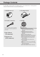
Package Contents The VB-C50Fi package contains the following items. If any of these items is missing, please contact the retailer from which you purchased the product. 1. VB-C50Fi main unit 2. AC adapter PA-V16 3. AC cable (1 meter/3 ft.) 4. CD-ROM Win d ow s is a registered trademark of Mi cr o s o in on rati rpo ft Co the d an S. U. h ot c er Ver. 1.0 J/E D70-0066-01 ou nt rie s. Co * The cable length may differ depending on the country in which the product was purchased.
-
Contents Introduction ............................................................................ ii Package Contents .................................................................. iv How to Read This Manual...................................................... ix aSafe Use of Equipment....................................................... x Maintenance ..............................................................................................................
-
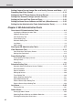
Contents Setting Camera Control, Image Size and Quality (Camera and Video) .... 3-7 Presetting Best Shot (Preset) .................................................................... 3-12 Setting Up the HTTP and Camera Servers (Server) ................................. 3-16 Setting User Access Privileges (Access Control) ................................... 3-20 Setting the Date and Time (Date and Time) .............................................. 3-23 Setting Up Name Server Address and Mail etc.
-
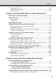
Contents Operating a Camera .............................................................................................. 4-66 Camera-Specific Functions .................................................................................... 4-68 Shade Correction .................................................................................................... x-xx Chapter 5 Creating Web Pages for Video Distribution Web Pages for Video Distribution ..........................................................
-
Contents Using VBCollector ........................................................................................ 6-9 Installing VBCollector ............................................................................................. Starting Up VBCollector ......................................................................................... Registering a Server .............................................................................................. Registering Tasks ..........................
-
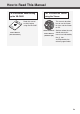
How to Read This Manual For information about setting up the VB-C50Fi NE TW OR K CA This manual describes how to use the Viewer for Java and the Viewer for PC. Sections where the user Viewer Software should refer to this User’s Manual manual are indicated by (Viewer-E.pdf) the d icon accompanied by the relevant page number. d ow s is a registered trademark of Mi cr o s o in on rati rpo ft Co the Plea Be se this sure read futu equ to this re ipm read refe ent. the inst renc Stor “aruct ion e.
-
a Safe Use of Equipment a An exclamation point, within a triangle, is intended to alert the user to the presence of important operating and maintenance (servicing) instructions in the literature accompanying the equipment. a Important Warnings a CAUTION: TO REDUCE THE RISK OF ELECTRIC SHOCK, DO NOT REMOVE COVER (OR BACK). NO USER-SERVICEABLE PARTS INSIDE. REFER SERVICING TO QUALIFIED SERVICE PERSONNEL. The serial number of this equipment may be found on the bottom of the VB-C50Fi.
-
a Safe Use of Equipment FCC NOTICE Network Camera, Model: VB-C50FiN, VB-C50FiP This device complies with Part 15 of the FCC Rules. Operation is subject to the following two conditions: (1) This device may not cause harmful interference, and (2) this device must accept any interference received, including interference that may cause undesired operation. Note: This equipment has been tested and found to comply with the limits for a Class B digital device, pursuant to Part 15 of the FCC Rules.
-
a Safe Use of Equipment a IMPORTANT SAFETY INSTRUCTIONS In these safety instructions, the word “equipment” refers to the Canon Network Camera VB-C50Fi and all its accessories. 1. Read Instructions - All the safety and operating instructions should be read before the equipment is operated. 2. Retain Instructions - The safety and operating instructions should be retained for future reference. 3. Heed Warnings - All warnings on the equipment and in the operating instructions should be adhered to. 4.
-
a Safe Use of Equipment fig-1 EXAMPLE OF ANTENNA GROUNDING AS PER NATIONAL ELECTRICAL CODE ANTENNA LEAD IN WIRE GROUNDING CLAMP ELECTRIC SERVICE EQUIPMENT ANTENNA DISCHARGE UNIT (NEC SECTION 810-20) a. When the power-supply cord or plug is damaged. GROUNDING CONDUCTORS (NEC SECTION 810-21) b. If any liquid has been spilled onto, or objects have fallen into, the equipment. GROUNDING CLAMPS NEC — NATIONAL ELECTRIC CODE 18.
-
a Safe Use of Equipment - Locations exposed to direct sunlight - Locations exposed to salt spray - Close to flammable solvents (alcohol, thinners, etc.) 22. When any of the following occurs, immediately switch OFF the equipment, unplug it from the main power supply and contact your nearest Canon supplier. Do not continue to use the equipment as this can cause a fire or electric shock. - The equipment emits any smoke, heat, abnormal noise, or unusual odor. - A metal object falls into the equipment.
-
a Safe Use of Equipment Maintenance Cleaning the Equipment 1. Unplug the AC adapter from the wall outlet. 2. Carefully wipe the equipment with a soft cloth that has been moistened with water or a mild detergent. a WARNING: Do not use flammable solvents such as alcohol, benzene or thinners. The use of such substances can cause a fire or electric shock. 3. Wipe with a dry cloth. 4. When you have finished, plug the AC adapter back in to the wall outlet.
-
xvi
-
Chapter Before Using the VB-C50Fi This chapter describes the features of the VB-C50Fi, the hardware and software requirements, and the name and functions of the system components.
-
Features of the VB-C50Fi The VB-C50Fi is a system that distributes live videos via the Internet or an Intranet. It can be used in a wide range of applications, such as distributing live videos from a Web site or monitoring. The system is configured for the VB-C50Fi and viewer software. Please use the supplied viewer software for viewing videos distributed by the VB-C50Fi and controlling cameras (→ P.1-4, 2-12).
-
Features of the VB-C50Fi View Restriction function You can set restrictions on camera zoom magnifications. For example, if the VB-C50Fi is showing camera footage on the internet, it is possible to distribute videos while protecting privacy (→ P.iii, “Request concerning disclosure of live videos”). Before Using the VB-C50Fi Built-in Web server and FTP server The VB-C50Fi is equipped with built-in Web server functions that enable both Web pages and videos to be distributed through the Web by a single unit.
-
Hardware and Software Requirements For the latest information, please refer to our WebView Product web page: http://www.canon.com/webview Viewer Software (→ d Viewer Software User’s Manual) The viewer software that is supplied with the VB-C50Fi lets you view the video captured by the VB-C50Fi and control the camera. Viewer for Java Ver. 3.6 Operating System Windows 2000 (SP4)/Windows XP (SP1a or SP2) Web Browser Netscape 7.1, 7.2, or Microsoft Internet Explorer 6.
-
Hardware and Software Requirements VBCollector Ver. 2.1 (→ P.6-9) This tool is for collecting and viewing still pictures recorded by the VB-C50Fi on a PC. Windows 2000 (SP4)/Windows XP (SP1a or SP2) Web Browser Microsoft Internet Explorer 6.0 (SP1 or SP2), Netscape 7.1 or 7.2 Hard Disk 20 GB HDD or greater required (NTFS formatted) Before Using the VB-C50Fi Operating System * Must be installed from the supplied CD-ROM (→ P.2-11).
-
Hardware and Software Requirements Multipoint Recording Software for Monitoring Use (Sold separately) Videos distributed from the VB-C50Fi can be recorded, and recorded video can be displayed with the software. Network Video Recorder VK-64/VK-16 v1.1 (Viewer System Requirements) Minimum Recommended CPU Pentium III, 700 MHz or greater Pentium 4 2.
-
System Components and Their Operation Front Screw hole for arm mounting Before Using the VB-C50Fi LAN status LED The LED blinks during communication. 100Base-TX .......................... Green 10Base-T ............................... Orange * You can set the LED to always light up even during communication. In this case, you can select from a green, orange or red light color. You can also set the LED to never light up (→ P.3-27).
-
System Components and Their Operation Rear On the rear of the VB-C50Fi there are the MAC address required for network settings, a Reset switch that returns the factory default settings and the serial number. MAC address The MAC address is required when setting the IP address and making other network settings. Please make a note of it before installing this unit (→ P.2-8). Screw hole for arm mounting Power connection socket Serial No. The serial number for this unit is shown here.
-
Multi-Terminal Module (VB-EX50) (Sold Separately) Using the Multi-Terminal Module (VB-EX50), you can connect external devices such as different kinds of sensors to the unit, and store images by sensor response (→ P.7-5). Please note that the Multi-Terminal Module (VB-EX50) is an optional product and is therefore sold separately. Before Using the VB-C50Fi * Audio input/output is not available with the VB-C50Fi. Example of Use With the Multi-Terminal Module, you can perform settings such as the following.
-
1-10
-
Chapter Setting Up This chapter explains how to set up the VB-C50Fi, run initial checks, and confirm that the camera’s images are displayed correctly.
-
Setup Workflow The flow for setting up and checking the camera’s images involves performing various settings after the device is set up and your PC and the network are connected via the hub. Then, check to see if you can display images from the camera. 1 Set up the camera Set up the device. Make sure the device is set up properly (→ P.2-4). VB-C50Fi 2 Connect the camera to the network Connect the camera and your PC via the hub (→ P.2-6).
-
Setup Workflow 5 Install the software Install the required software in advance for operating the camera (→ P.2-11). Setting Up 4 Check operation of the camera Access the device with your PC, then display to check the image from the top page of the camera server (→ P.2-10).
-
1. Set Up the Camera Firstly, set up the camera. Read the following carefully and make sure the camera is set up properly. Installing the VB-C50Fi Attach a mounting arm (not included) to the ceiling or a wall and firmly attach the camera to the arm. a WARNING: Install the camera securely. ● When installing the VB-C50Fi on the ceiling or a wall, contact your Canon dealer.
-
1. Set Up the Camera Using the Wide Converter The optional Wide Converter WL-37 can be used to provide wide-angle shots (approx. 0.74× the normal focal distance). Mount the wide converter correctly so that it is level and fitted securely onto the camera. When mounted correctly, the wide converter should turn roughly 3 times before stopping. Setting Up Wide Converter - ● The camera may not operate correctly if a wide converter other than the WL-37 is used.
-
2. Connect the Camera to the Network Next, connect the camera. Connect the camera to the network by connecting the camera and PC via the hub with a LAN cable . * Do not plug the AC cable power plug into the wall socket yet. AC cable Hub (Rear of main unit) Notebook AC adapter LAN cable Turning the Power ON and OFF The VB-C50Fi itself does not have a power switch. You can switch the VB-C50Fi on by plugging the AC adapter into a wall outlet. The LED flashes when the VB-C50Fi is communicating.
-
3. Perform Initial Settings for the Camera Once your PC and the camera are connected, perform the initial settings next. The instructions here follow on from “2. Connect the Camera to the Network”, where one camera is connected to a PC as an example. Installation Example VB-C50Fi Setting Up LAN cable Hub 1. Turn on the network device (in this case, the hub) and then your PC. Do not turn on the camera at this stage. Note 2. Insert the CD-ROM provided into your PC and from Explorer etc.
-
3. Perform Initial Settings for the Camera 3. The camera connected to the network is automatically detected and its MAC address, IP address and model name are displayed. Click to select The factory default setting is: IP address : 192.168.100.1 The MAC address can be found on the warranty card or on the white label attached on the rear of the unit. Note that VBSetup.exe cannot be used across subnets. Click the MAC address to select it, and click the “Initial Setup” button. 4.
-
3. Perform Initial Settings for the Camera 5. A setup progress window appears and your settings will be saved. Setting Up Note ● Set the IP address to a value that suits your environment. ● Where the IP address has been automatically obtained from the DHCP server, you cannot change the IP address setting from the VB Initial Setup Tool. If you wish to change the IP address, change it from the Network Settings page (→ P.3-6).
-
4. Check Operation of the Camera When you have completed the initial setup, check that the VB-C50Fi works normally. Use the sample page to simplify checking. 1. Select the MAC address you want to check operation of and then click the “Open Test Page”. 2. Your Web browser starts up and the top page of the camera server appears. Click the “Using Viewer for Java” or the “Using Viewer for PC” and check that the video is displayed properly.
-
5. Install the Software You must install software to display images from the camera and to manage the camera. There are 3 types of software you can install. • VB Administration Tools: Software for managing the camera (→ P.4-2). • Viewer for PC: Software for displaying images from the camera (→ P.2-12). • VBCollector: Software for collecting and viewing pictures taken by the camera to be stored on a PC (→ P.6-9). Setting Up 1.
-
Viewer Software Overview By using the Viewer software, you can view images sent from the VB-C50Fi on a PC, as well as control the camera. Below is an outline of the Viewer software. For details, please refer to “Viewer Overview” (→ P.5-4) or to the Viewer Software User’s Manual (Viewer-E.pdf) on the CD-ROM. Viewer Software Types There are 2 types of viewers described below. ● Viewer for PC When started up, this viewer displays as a separate window. The viewer is installed beforehand on the PC to be used.
-
Chapter Basic Settings This chapter describes the basic settings for the VB-C50Fi such as network connection, camera control, date and time setting and mail. Be sure to perform these settings after setting up. * The VB Administration Tools (→ P.4-2) described in Chapter 4 provide a convenient way to set view restrictions as well as presets.
-
What Can I Do on Each of the Settings Pages? Proceed to each of the settings pages from the Settings Title Page where you can perform various settings for the VB-C50Fi. The settings you can perform on each of the pages are shown below. For more details, see the reference pages. ● System and network For setting administrator passwords and networks (Ethernet, network connection function) (→ P.3-5) ● Camera and Video For setting video capture (image size and quality etc.
-
Accessing the Settings Title Page The various settings on the VB-C50Fi are specified by using a browser to access Web pages on the VB-C50Fi. To begin with, access the Settings Title Page. Note This manual uses the IP address 192.168.100.1 (the factory default setting) below as an example to describe the detail settings. Please enter the actual IP address that is set in your VB-C50Fi. 1. Use the browser to access http://192.168.100.1/admin/.
-
Settings Title Page From the Settings Title Page, you can move to each settings page, confirm the settings after changing, and save the changes to the VB-C50Fi’s memory or3restart. 5 3 4 1 2 1 “Back to top” button Click “Back to top” to move to the top page of the camera server. 2 “Japanese” or “English” button Click this display to show the settings page in Japanese. The display then changes to “English” and when clicked, switches back to the English settings page.
-
Setting Up the Administrator Password and Ethernet etc. (System and Network) Basic Settings You can perform the following settings with System and Network. ●Root Account: For setting up passwords. ●Ethernet: For setting up IP addresses and other settings necessary for connection to the network. ●Connection Keeping: For setting up the function whereby packets are periodically transmitted and there is automatic dial-up by the router so that the connection with the network is not broken.
-
Setting Up the Administrator Password and Ethernet etc. (System and Network) Ethernet 1 2 3 4 5 1 “Address Setting Method” Select an address setting method from “Auto Setting (DHCP)” or “Manual Setting”. If you select “Auto Setting (DHCP)”, you can use the values automatically obtained from the DHCP server for “IP Address”, “Subnet Mask” and “Default Gateway Address”. If you select “Manual Setting”, directly enter values which suit your environment.
-
Setting Up the Administrator Password and Ethernet etc. (System and Network) Connection Keeping 1 2 3 1 “Send packet regularly” Check to enable this function. Basic Settings 2 “Target IP Address” Specify where the packet should be sent. 3 “Interval (min.)” Specify the interval at which a packet should be sent from 1 to 60 (min.).
-
Setting Camera Control, Image Size and Quality (Camera and Video) You can perform the following settings with Camera and Video. ● Video Capture: For setting image size and quality. ● Camera Control: For setting the camera shutter speed, focus, home position and view restrictions. ● Camera Names: Enter camera names. A camera name is required when you use an external camera or the VK-64. When you have made changes to the settings, click the “OK” button to return to the Settings Title Page.
-
Setting Camera Control, Image Size and Quality (Camera and Video) 3 “Interlace Mode” Select either “Weave (Interlace)” (for subjects which move a little) or “Bob (Non-Interlace)” (for subjects which move a lot), according to the range of the movement. You can obtain high-resolution video if you set “Video Capture Size” to “Large Size”. However if the subjects move quickly and sharply, you may encouter comb-shaped blurs in the video. “Bob” is more effective for quickly moving subjects.
-
Setting Camera Control, Image Size and Quality (Camera and Video) 3 “Home Position” This is the specified camera settings. When this is specified, the camera settings return to the specified settings if there is no request for control privileges. “Zoom” Sets the value for the camera’s angle of zoom. “Brightness” Sets the target value for the camera’s auto exposure feature. Select “Brighter” if the picture is too dark due to backlight or other factors.
-
Presetting Best Shot (Preset) Common Settings Basic Settings You can perform the following settings with Preset. ● Common Settings: For setting the tour schedule of present position. ● Preset 1-10: You can register up to 10 specified zoom magnifications as preset positions. When you have made changes to the settings, click the “OK” button to return to the Settings Title Page. If you do not make any changes, click the “Cancel” button.
-
Presetting Best Shot (Preset) 1 “Restrict Camera Control to Presets” Camera control by using the Viewer for PC and the Viewer for Java can be restricted to the preset zoom positions specified in Preset 1-20. “Auto Preset Tour” Select a Preset Tour setting from the following options. “Not used” Preset Tour does not operate. “For Viewers” Operates if any of the Viewer for Java, Viewer for PC or Admin Viewer is connecting. “Always” Preset Tour always operates.
-
Presetting Best Shot (Preset) Preset 1-10 1 2 3 Basic Settings 1 “Application” Use these options to specify whether this preset can be used only for picture recording or is also made available in the viewers. If it is also provided in the viewers, always specify the preset name. 2 “Preset Name” Enter a name consisting of up to 15 alphanumeric characters. 3 “Camera Parameter” Set the video capture settings to be provided. “Zoom” Sets the value for the camera’s angle of zoom.
-
Setting Up the HTTP and Camera Servers (Server) You can perform the following Settings with Server. ● Common Settings: For setting up the environment where users can connect to the VB-C50Fi. ● HTTP Server: For setting web page distribution and managing the VB-C50Fi. ● Camera Server: For setting up the viewing of video from the VB-C50Fi. When you have made changes to the settings, click the “OK” button to return to the Settings Title Page. If you do not make any changes, click the “Cancel” button.
-
Setting Up the HTTP and Camera Servers (Server) HTTP Server 1 2 2 “Global Address for Web Pages” If a private address has been set in the VB-C50Fi and you want to use the router’s NAT functions to have a fixed global address for the VB-C50Fi (→ P.5-26), enter a global address here, and this will let you view sample pages (→ P.5-6). If “IP Address” is selected, enter the IP address specified in “IP Address”. If “Host Name” is selected, the host name specified in “DNS” in “Miscellaneous” is used.
-
Setting Up the HTTP and Camera Servers (Server) Camera Server 1 2 3 4 5 6 7 1 “Video Transmission Port” Sets the TCP port number for the video transmission protocol. Enter a value between 1 and 65535. The default setting is 65310. Normally, there is no need to change this setting. 2 “Camera Control Port” Sets the TCP port number for the camera control protocol. Enter a value between 1 and 65535. The default setting is 65311. Normally, there is no need to change this setting.
-
Setting User Access Privileges (Access Control) You can perform the following settings with Access Control. ●Authorized User Account: Register users who may connect to the VB-C50Fi. ●Authorized/Restricted Host Specification: Control whether a specific host is to have access or not. Authorized User Account Basic Settings When you have made changes to the settings, click the “OK” button to return to the Settings Title Page. If you do not make any changes, click the “Cancel” button.
-
Setting User Access Privileges (Access Control) Authorized/Restricted Host Specification 1 2 3 4 1 “Host List” In this Host List, you can in detail whether of how access from the hosts is permitted or denied. See the next page for the description format. 2 “Apply this list to HTTP server” When this is selected, the Host List is applied to the host that can access the HTTP server. In this case, control extends also to the Viewer for Java, etc.
-
Setting User Access Privileges (Access Control) Tip The Host Restriction function applies to hosts running client applications such as viewer. Access restrictions are imposed using a list made up of one or more entries written using the format described below. Listing Format Listing Guidelines Basic Settings [!] addr [-addr2] ● “addr” is written in standard IP address format.
-
Setting the Date and Time (Date and Time) You can perform the following settings with Date and Time. ● Current Camera Time: Displays the time set up for the camera. ● New Camera Time: For setting up the time on the VB-C50Fi. ● Time Zone: Select the appropriate time zone from the list. When you have made changes to the settings, click the “OK” button to return to the Settings Title Page. If you do not make any changes, click the “Cancel” button.
-
Setting the Date and Time (Date and Time) New Camera Time 1 2 1 “Synchronize with computer time” Sets to the date and time of the PC currently accessing the VB-C50Fi via a Web browser. Basic Settings 3 2 “Set manually” Select this item when the date and time are to be manually entered. In the Date field, enter the year, month and day in yyyy-mm-dd format; in the Time field, enter the time in hh:mm:ss 24hour format. For example, for January 23, 2004, 1:23:04 p.m., enter “2004/01/23” and “13:23:04”.
-
Setting Up Name Server Address and Mail etc. (Miscellaneous) You can perform the following settings with Miscellaneous. ● DNS: Register the Name Server Address and Host Name for registering host names such as Mail Server Host. ● Mail: For setting up the mail addresses which are to receive recorded pictures and log messages. ● External Device Names: For setting up the names for the external devices to be used with WebView Livescope MV etc. ● LED: For setting the LED on the VB-C50Fi to turn on or off.
-
Setting Up Name Server Address and Mail etc. (Miscellaneous) Mail 1 2 3 4 5 1 “Mail Server Host” Specifies the SMTP server. 2 “Sender’s (From) Mail Address” Specifies the mail sender. Basic Settings 6 3 “Recipient (To) Mail Address” Specifies the mail recipient. 4 “POP before SMTP” Set up if the mail host server requires POP user authentication. 5 “User Name” and “Password” Specify the settings in “User Name” and “Password” necessary for authentication. 6 “POP Server” Sets up the POP server.
-
Setting Up Name Server Address and Mail etc. (Miscellaneous) External Device Names 1 2 1 “External Input Device 1-2” “Device Name” To distinguish between the different external devices connected to the Multi-Terminal Module, be sure to enter a device name. Enter a device name consisting of up to 15 alphanumeric characters. 2 “External Output Device 1-3” “Device Name” To distinguish between the different external devices connected to the Multi-Terminal Module, be sure to enter a device name.
-
Setting Up the Administration Tools (Administration Tools) If you do not make any changes, click the “Cancel” button. On-board File System Information Basic Settings You can perform the following settings with the Administration Tools. ●On-board File System Information: Displays the status of VB-C50Fi’s memory. ●Recorded Picture Information and Manipulation: Displays the status of pictures recorded in the VB-C50Fi and deletes recorded pictures.
-
Setting Up the Administration Tools (Administration Tools) Miscellaneous 1 2 3 4 1 “View Log Events” Click the “View” button to see the historical log files of the VB-C50Fi’s operation, such as connection with viewers, etc. 2 “View Current Settings” Displays a list of current settings. 3 “Reboot” Reboots the VB-C50Fi. 4 “Restore Settings” All but the password setting, ethernet setting method, IP address, subnet mask and default gateway of the VB-C50Fi will be restored to the factory default settings.
-
Chapter VB Administration Tools Chapter 4 describes practical ways of operating the VBC50Fi using the VB Administration Tools to set view restrictions, set presets and schedules, view logs and use the Admin Viewer. Review the necessary basic settings in Chapter 3 before proceeding to Chapter 4. * Although view restrictions and presets can be set by following the procedures described in Chapter 3, the VB Administration Tools are more visual-based and easy to use.
-
Overview of VB Administration Tools VB Administration Tools comprises “VBAdmin Startup Panel”, “View Restriction Tool”, “Preset Setting Tool”, “Schedule Setting Tool”, “Log Viewer” and “Admin Viewer” applications. Operations such as setting the VB-C50Fi or viewing pictures from a remote location with special privileges, checking operating status or obtaining logs are easily performed through the Internet or Intranet.
-
Overview of VB Administration Tools VBAdmin Startup Panel (→ P.4-5) This is the main panel of VB Administration Tools. The tools are started up from this panel. Install VB Administration Tools first from the supplied CD-ROM. VB Administration Tools Panorama Creation Tool * Not available with the VB-C50Fi. View Restriction Tool (→ P.4-12) This tool enables easier, more visual setting of view restrictions. Restrictions can be set by operating the mouse. Preset Setting Tool (→ P.
-
Overview of VB Administration Tools Schedule Setting Tool (→ P.4-27) With the Schedule Setting Tool you can set up the following services to perform automatically on a specified day or time. ● Timer: Photographs still images at specified times and records them in the VB-C50Fi. ● Motion Detection: Detects changes in the image and performs video recording automatically. ● Night Mode: Takes shots in dark conditions.
-
Starting Up VB Administration Tools ○○○○○○ To Start Up... 1. Double-click the “VB Admin Tools” desktop icon or select “VB Admin Tools” from the “Start” menu. Starting up from the desktop icon Starting up from the “Start” menu 2. The Server Setting dialog box appears. VB Administration Tools To use VB Administration Tools, it must first be connected to the VB-C50Fi. Enter the required information in the fields and click the “OK” button. q w e r t y q Host Name (→ P.
-
Starting Up VB Administration Tools 3. The VBAdmin Startup Panel starts up. The five tools---“View Restriction Tool”, “Preset Setting Tool”, “Schedule Setting Tool”, “Log Viewer” and “Admin Viewer”---can be started up from the Startup Panel by clicking on each button. If the connection is broken after the VB Admin Startup Panel has started up, choose Connect from the File menu. The Server Setting dialog box then appears.
-
View Restriction Tool The View Restriction Setting Tool is a tool that allows you to set the zoom range easily with the mouse. VB Administration Tools The View Restriction Tool lets you easily set view restrictions in cases where you want to set restrictions on zoom when videos are distributed live or in other such instances. Only the range set in the view restriction is displayed in the viewer.
-
View Restriction Tool View Restriction Tool Display Screen An overview of the functions of the GUI displayed when the View Restriction Tool starts up is shown below. q w e r t y u i !1 !0 o q “Load Settings” button Loads the view restriction settings set in the VB-C50Fi. w “Save Settings” button The View Restriction setting value set and applied with this tool is saved to the VB-C50Fi.
-
View Restriction Tool t Camera Selection box Select the camera to be used to apply view restriction settings. y “Apply the view restriction” View restriction settings are applied when this item is selected. VB Administration Tools u View Restriction Value Input boxes and “Get Value” button The view restriction settings can be edited by entering values in the View Restriction Value Input boxes.
-
View Restriction Tool Setting View Restrictions You can set up a view restriction by either entering a value in the view restriction setting input box or by using the following 2 methods. Select the way which suits your environment or according to your preference. ■ Changing Settings from the View Restriction Preview Frame The View Restriction Preview frame can be used to set view restrictions. ○○○○○○ To Make Settings... 1. Select “Apply the view restriction”. 2.
-
View Restriction Tool Retrieving Values from the Camera Zoom Position of the Admin Viewer and Changing Settings Admin Viewer can be used to set the view restriction while confirming camera images. ○○○○○○ To Make Settings... 1. Select “Apply the view restriction”. 2. Click the “Admin Viewer” button to start it up. VB Administration Tools 3. In Admin Viewer, click the “Start Control” button to obtain control rights for the camera. 4.
-
View Restriction Tool Note Tip 4-12 After the view restrictions have been set, please check to be sure the viewer is correctly reflecting the view restrictions. When checking from the Admin Viewer, choose “View Restriction” - “ON” from the “Privilege” menu bar (→ P.4-66). ● When you want to clear the view restriction settings, clear the “Apply the view restriction” check box, click the “Apply” button and then the “Save Settings” button.
-
Preset Setting Tool The Preset Setting Tool enables you more visually and easily to set Presets and home position. Presets are set by operating the mouse. You can also enter settings for a Preset Tour with which you can tour and monitor two or more Presets within a specified start and end time. VB Administration Tools After setting presets, set the preset tour.
-
Preset Setting Tool Preset Setting Tool Display Screen The display screen for the Preset Setting Tool is divided into the “Preset Settings Area” and the “Preset Tour Settings Area”. A maximum of 10 Presets and home positions can be set. In the “Preset Tour Settings Area”, you can enter settings for a Preset Tour with which you can tour and monitor two or more presets within a specified start and end time. Below is a description of the “Preset Setting Area” screen.
-
Preset Setting Tool t Preset Selection box Select the preset to set or “Home”. “Home” is the setting for home position. y “For picture recording only” When this is checked, presets are used for picture recording only; when it is not checked, presets can be used not only for picture recording but for the viewer as well. If you selected “Home” in the Preset Selection box, this setting will be grayed out (setting not possible). u Preset Name A name can be assigned to the preset.
-
Preset Setting Tool Setting Presets You can set up Presets by either entering a value in the camera parameters or by using the following 2 methods. Select the way which suits your environment or according to your preference. Changing Settings from the Preset Preview Frame The Preset Preview frame can be used to set presets. ○○○○○○ To Make Settings... 1. From the Preset Selection box, select the preset to be set and enter a name in “Preset Name”. 2.
-
Preset Setting Tool Retrieving Values from the Camera Zoom Position of the Admin Viewer and Changing Settings Start up Admin Viewer and set the camera zoom position as a preset. ○○○○○○ To Make Settings... 1. From the Preset Selection box, select the preset to be set, and enter the “Preset Name”. 2. Click the “Admin Viewer” button to start it up. VB Administration Tools 3. Click the “Start Control” button in the Admin Viewer to obtain camera control rights for the camera. 4.
-
Preset Setting Tool Tip 4-18 ● You can set a maximum of 10 presets. ● Changes in the preset settings are not reflected to the viewer while it is connected. ● After the presets have been set, please check to be sure the viewer is correctly reflecting the presets. ● Once presets have been set, they cannot be deleted. If you do not want to these presets to be used, select “For picture recording only” so that the presets cannot be used in the Viewer for PC.
-
Preset Setting Tool Preset Tour A Preset Tour can tour and monitor two or more specified Presets. You can also set Preset Tour with “Presetting Best Shot” in Chapter 3, “Basic Settings” (→ P.3-12). Preset Tour Settings Area Display Screen q w e y u r VB Administration Tools i o !0 t q Tour Schedule list Displays a list of the presets which have Preset Tour settings. w “Add” button Adds a preset to the Tour Schedule List.
-
Preset Setting Tool o Speed (Z) Sets the speed at which the camera moves when zooming, within a range of 1-8. By moving the slide bar from left to right, the numeric value becomes larger and the speed increases. !0 Pause (sec) Sets the time for which the camera pauses in the preset position, within a range of 0-120 seconds in units of five seconds. Tip 4-20 Preset Tour does not operate when the camera is being controlled with the Viewer for PC, or the Admin Viewer and so on.
-
Preset Setting Tool Setting Preset Tour ○○○○○○ Setting up 1. Select an option from Auto Preset Tour. Select either “For Viewers” or “Always”. The preset is registered in the Tour Schedule list. You can register a maximum of 10 presets. 3. Select a preset in the Tour Schedule list and with the slide bars in Speed (Z) and Pause (sec), set the speed for zooming for each preset and the number of seconds for the pause in preset position. VB Administration Tools 2.
-
Schedule Setting Tool With the Schedule Setting Tool, you can set up Timer, Motion Detection, Night Mode, External Device Input and External Device Output services to perform automatically on a specified day of the week or time of the day. You can set a start and end time and the content of the service on the calendar in the Schedules Setting screen. 1. Select either Normal Schedule or Special Schedule and enter settings for the schedule.
-
Schedule Setting Tool Schedule Setting Tool Display Screen (Toolbar) There are two kinds of Schedule settings, Normal Schedule and Special Schedule. The buttons in the toolbar below can be used for both Normal and Special Schedules. With these buttons, you can load and save setting information, stop communication, select Normal schedule (→ P.4-29) and Special schedule (→ P.4-33) as well as open each service setting screen (→ P.4-39, 4-41, 4-52, 4-54, 4-56).
-
Schedule Setting Tool Normal Schedule With Normal Schedule, you can set up a schedule of one week from Sunday to Saturday. For example, during the weekend when there is nobody in the office from 6:00pm on Friday to 9:00am on Monday, the Motion Detection service will operate each week during the period of time you have specified and automatically monitor the office. Normal Schedule Display Screen q w e r t q Schedule selection checkbox Check to select the number of the schedule you want to set up.
-
Schedule Setting Tool Setting Up a Normal Schedule ○○○○○○ To Make Settings... 1. With the Normal Schedule displayed, select an optional schedule number. The schedule track for the number you have selected is displayed in the weekly calendar. At this stage, the correct start and end time and services are not set up in the schedule track. You can change the color of the schedule track by right-clicking a schedule number and selecting “Color Setting”. 2. Double-click the schedule track.
-
Schedule Setting Tool Tip ● On Weekly setting, if you specify the same time and the same day in start and end time, end time will be the same time in the following week, and the schedule is applied to all time periods. ● On Weekly on setting, if you specify the same start and end time, the end time will be on the following day at the same time. ● If you enter “24:00” as the start or end time, the time will be registered as “23:59”. To set “24:00”, enter “00:00” on the following day. 5.
-
Schedule Setting Tool 6. When you have completed setting the subschedule tracks, click “OK” button. If you want to set two or more schedule tracks, select another number in the schedule selection checkbox, and make settings in the same way. VB Administration Tools Tip ● You can register different settings for each setting number. The number of setting numbers that can be registered differs depending upon the service.
-
Schedule Setting Tool Special Schedule With Special Schedule, you can set up a schedule on one specific day of the week. For example, on a public holiday when there is nobody in the office, set up a service to automatically monitor the office. Special Schedule Display Screen q w r e t y q Set Special Day selection box Select the special day you want to register from special days A-D or select “Erase Special Day”. w “Special Day List” button Click to display the Special Day List dialog box.
-
Schedule Setting Tool Setting Up a Special Schedule ○○○○○○ To Make Settings... 1. With the Special Schedule displayed, select from the Special Day selection box the Special Day you want to register in the Schedule. Click the date on which you want to register a Schedule and the Special Day you have selected is registered. VB Administration Tools Tip ● You can only set one type of Special Day per day. ● You can set one Special Day a maximum of 32 times.
-
Schedule Setting Tool 3. Double-click the sub-schedule track. The Special Schedule Settings dialog box appears. Enter settings for the schedule. 4. Enter the name of the Special Day Schedule. You can enter a maximum of 15 characters for the Special Day Schedule. The schedule name you enter here is the name for the Special Day schedule (A–D), which is different from the Sub-schedule name. You cannot set a name for a Sub-schedule. 5.
-
Schedule Setting Tool 6. Display the Service tab and enter settings for the services. For more information about the services you can set, please see page 4-31. Tip ● The Service Setting screen can also be displayed by clicking a button on the toolbar for each service. ● Where settings for the services have been entered from the Service tab in the Schedule Setting screen, the selected setting number cannot be changed with the Service tab. 7.
-
Schedule Setting Tool Tip ● An icon for the service you have set up appears in the schedule track in the calendar. However, where the schedule track is short, it may be that not all of icons are displayed. The icons displayed for each service are as follows: “Timer” “Motion Detection” “External Device Input” “External Device Output” “Night Mode” ● The days and start and end times set in the Schedule tab are shown by the position and length of a schedule track.
-
Schedule Setting Tool Resetting Schedule Settings Resets schedules you have set. 1. In the Normal or Special Schedule Setting screen, select “Initialize normal (special) schedules” from Edit in the menu bar. Tip If you want to reset normal and special schedules at the same time, select "Initialize all schedules and service settings" from Edit in the menu bar.
-
Schedule Setting Tool Setting Up Service Set up the services to be performed in the schedules. “Service tab” in the Schedule Setting screen To open the settings screen for each service, in the “Service” tab in the Schedule Setting screen, select the service you want to set up, select a setting number and click “Detail”. Select the service you want to make settings for, select a setting number and click the “Detail” button. There are 5 types of services you can set up.
-
Schedule Setting Tool Timer Setting Tool The section below describes the “picture recording” function which takes still images at specified times and records them in the VB-C50Fi. Timer Setting Tool Display Screen qwe q “Load Settings” button Loads the timer settings currently set in the VB-C50Fi. w “Save Settings” button Saves the timer settings edited using this Tool. After setting the timer function, be sure to click the “Save Settings” button to save the settings.
-
Schedule Setting Tool o Disable movement to the home position and auto preset tour Check to deactivate movement to home position and Preset Tour during picture recording. You can only enter a tick if a preset is specified in “Camera Preset” and “Repetition Interval” is set to more than 30 seconds. !0 Enable auto playback * Not available with the VB-C50Fi. !1 Sound Clip and Volume * Not available with the VB-C50Fi. !2 Repetition Interval * Not available with the VB-C50Fi.
-
Schedule Setting Tool Motion Detection Setting Tool The section below describes the motion detection function which records pictures, sends data to external devices and records data in the log when there is a variation in all or part of the picture resulting from objects moving around. Note Notes on Using This Function The Motion Detection Function is not suited to applications where high levels of reliability are demanded.
-
Schedule Setting Tool t Camera Selection box For selecting a camera. y Viewer For picture display and camera control in the same way as a normal viewer. u Motion detection area frame Displays with a dotted frame the area within which motion is to be detected. The frame can be reshaped and moved by dragging the mouse. i “Rec. Start” button Starts recording of the picture. o Setting number selection box Select the number of the setting you want to use.
-
Schedule Setting Tool Flow of Motion Detection Settings A summary of the procedures for motion detection is given below. Please refer to each reference page for information about detailed setting content. 1. Open the Motion Detection Tool. The Motion Detection Tool Setting screen appears (→ P.4-41 “Motion Detection Setting Tool Display Screen”). Enter settings for motion detection in the Settings tabs on the right of the screen.
-
Schedule Setting Tool Setting Up Motion Detection ○○○○○○ To Make Settings... 1. Open the Motion Detection Setting Tool with the Schedule Setting Tool. In the Service tab in a Normal or Special Schedule Setting screen, check Motion Detection, select a setting number and click “Detail” (→ P.4-38). 2. Set the camera frame rate and the camera position for detection (Camera tab). q Set the camera frame rate and camera position.
-
Schedule Setting Tool 3. Create a motion detection area (Area tab) Create an area in the viewer within which motion detection is to be performed (motion detection area). You can create a maximum of 4 motion detection areas, and reshape and move each area frame by dragging the mouse. Change the shape by dragging the black boxes on the 4 corners and sides of the frame, and move the frame by dragging the inside of it with the mouse. Also, you can set a separate level of motion detection in each area.
-
Schedule Setting Tool y Area Ratio When the proportion of the area in which the device has detected motion (displayed in a red or yellow rectangle) has exceeded the specified value for the area of the selected detection area frame (blue frame), the device detects motion and performs the specified picture recording etc. (However, even if the area ratio value is exceeded, the device does not detect motion unless the number of seconds specified in Duration has passed).
-
Schedule Setting Tool 5. Enter the settings for Recording when the device detects motion (Recording tab). Enter the settings for picture recording time and recording interval when the device detects motion (ON event) or when the device no longer detects motion (OFF event). q w e r q “Recording at ON event” Check for picture recording when the device detects motion (ON event). w “Recording at OFF event” Check for picture recording when the device no longer detects motion (OFF event).
-
Schedule Setting Tool 6. Enter the settings for output to an external device when the device detects motion (Output tab). q w * The settings in these steps are optional. Set output to an external device when the device has detected motion (ON event) or when the device has finished detecting motion (OFF event). q Output to External Devices 1-3 Check for Output to External Devices 1-3. w Output duration after OFF event (sec.
-
Schedule Setting Tool 7. Check motion detection status in the server. To confirm the operating level of motion detection with the settings you have made, check “Display Motion Detection Status of the Server”. Motion detection status is displayed as the icon below. [Detection disabled] [Detected] [Not detected] Tip VB Administration Tools Note ● Normally, the Motion Detection Tool simulates in your PC the operation of the VBC50Fi’s motion detection module.
-
Schedule Setting Tool Motion detection status and screen display Tip The area in which the VB-C50Fi is performing motion detection appears in a blue frame in the Viewer. The selected sensitivity at which the VB-C50Fi is performing motion detection appears as a yellow or red rectangle in the motion detection frame. Yellow rectangle: Where the device has detected motion, but because Area Ratio and Duration have not reached their setting value, the device does not detect motion.
-
Schedule Setting Tool Tip Setting the motion detection level while checking recorded images To set the level of motion detection at motion detection is activated, it is useful to make adjustments to settings while checking actual actions in the Viewer. Because with the device you can set the level of motion detection by checking in Video Mode the pictures recorded in Live Mode (→ P.441) in the Mode tab, you do no need to repeat the actual actions in front of the camera.
-
Schedule Setting Tool Night Mode Setting Tool Below is a description of the Night Mode function with which you can take pictures in dark conditions. Night Mode Setting Display Screen q w e r t y u q “Load Settings” button Loads the Night Mode settings currently set in the VB-C50Fi. w “Save Settings” button Saves the Night Mode settings edited using this Tool. After setting the Night Mode function, be sure to click the “Save Settings” button to save the settings.
-
Schedule Setting Tool Setting Up Night Mode ○○○○○○ To Make Settings... 1. With the Schedule Setting Tool, open the Night Mode Setting Tool. In the Service tab of the Schedule Setting screen for a Normal or Special Schedule, check Night Mode, select a setting number and click the “Detail” button (→ P.4-38), or click the “Night mode setting tool” button on the toolbar.
-
Schedule Setting Tool External Device Input Setting Tool Below is a description of the External Device Input function which performs video recording when a signal from an external device connected to the Multi-Terminal Module (→ P.1-10) such as a sensor is input into the device. External Device Input Setting Tool Display Screen qw e r t y u i o !0 !1 !2 !3 !4 !5 q “Load Settings” button Loads the External Device Input settings currently set in the VB-C50Fi.
-
Schedule Setting Tool !0 Post-event (sec.) and Interval Enter the required number of seconds, within a range of 0-10 seconds for picture recording following an ON and OFF event. Also enter an interval for performing picture recording, within a range of 0.1-1.0 seconds. !1 “E-mail notification on recording” Check to send an e-mail of the recorded picture. !2 Sound Clip and Volume Set the audio for playback. Select from the registered playback audio names.
-
Schedule Setting Tool External Device Output Setting Tool The section below describes the output settings to an external device connected to the MultiTerminal Module (→ P.1-10). External Device Output Settings Tool Display Screen q w e r t y u i q “Load Settings” button Loads the External Device Output settings currently set in the VB-C50Fi. w “Save Settings” button Saves the External Device Output settings edited using this Tool.
-
Schedule Setting Tool Setting Up External Device Output ○○○○○○ To Make Settings... 1. With the Schedule Setting Tool, open the External Device Output Setting Tool. In the Service tab of the Schedule Setting screen for a Normal or Special Schedule, check Output1-3 in External Device Output, select a setting number and click the “Detail” button (→ P.4-38), or click the “External device output setting tool” button on the toolbar.
-
Schedule Setting Tool Relationship between ON and OFF events and picture recording Tip ON OFF Picture Recording A B C D Below are methods (A-D) for picture recording with motion detection and external device input based on the timing of ON and OFF events. OFF ON A: Pre-event recording for an ON event (for 0-10 seconds at intervals of 0.1-1.0 seconds) ON OFF C: Pre-event recording for an OFF event (for 0-10 seconds at intervals of 0.1-1.
-
Schedule Setting Tool E-mail Notification Settings dialog box Tip When pictures have been recorded, you can send the recorded pictures and data in an e-mail. Settings for sending mail messages are performed in the E-mail Notification Settings dialog box. Select E-mail Notifications Settings from Tools in the menu bar in the Motion Detection Setting screen or External Device Input Setting screen and the dialog box appears.
-
Log Viewer The Log Viewer is a tool for downloading log files, and viewing and managing the operating status of the device. The Log Viewer provides monitoring of illegal access and a way of dealing with errors etc. Tip The Log Viewer is only for viewing logs. You cannot delete logs or download logs in file formats such as CSV with the Log Viewer. Downloading Log Files ○○○○○○ How to download 1.
-
Log Viewer Viewing the Log The following content is displayed in the log. ● Code The log displays error codes. For error codes, refer to Log Messages (→ P.5-30). Error codes are displayed with one of 4 types of icons according to level. Information level Error level Warning level Unknown Saving a Log to a File/Opening a Saved File ○○○○○○ You can save a displayed log to a file as well as view a previously saved log file. To Save... 1. Choose “Save” from the “File” menu bar.
-
Log Viewer Using Selection Criteria to Display Logs Logs can be filtered according to error type, code, or date and time so that only the required information is displayed. ○○○○○○ To Set Selection Criteria... 1. Choose Filter from the View menu. 2. The Filter dialog box appears. Set the following selection criteria and click “OK” to display only the logs that match those criteria. If filtering is not required, click “Cancel”.
-
Admin Viewer Admin Viewer is a viewer which has functions for managing the VB-C50Fi. It has special privilege functions that the Viewer for PC and Viewer for Java do not have, such as exclusive access to camera control functions, and external device and motion detection operation. This viewer is used when setting view restrictions and presets. [Special privileges of Admin Viewer] “Control” button Click this button to obtain camera control privileges.
-
Admin Viewer Starting Up Admin Viewer ○○○○○○ To Start Up... 1. Click the “Admin Viewer” on the VBAdmin Startup Panel or double-click the “Admin Viewer” icon on the desktop. When the Admin Livescope window appears, click the File then the Connect. The “Camera server address setting” dialog box appears. Enter the following items: ● Host Name (The IP address set on the VB-C50Fi, → P.3-6) ● User Name (root) ● Password (→ P.3-5) Then click the “OK” button. The video will then be displayed.
-
Admin Viewer A message appears in the event a change occurs in the external device input status or when motion is detected. Note If the Admin Viewer window is minimized or in full-screen mode, the notification message for external device input appears after the normal display is restored. Also, this message is not displayed when the External Device Input & Motion Detect dialog box is displayed. The external device input and motion detection status can be displayed and, when required, saved as a log.
-
Admin Viewer Operating External Device Output The ON/OFF status of external device output can be changed. ○○○○○○ To Set External Device Input... 1. Click the “Start Control” button to get camera control privileges, then choose External Device Output from the Privilege menu. 2. The External Device Output dialog box appears. The external device output status can be changed using the ON/OFF buttons for each terminal. To close the dialog box, click “Close”.
-
Admin Viewer Operating a Camera The Admin Viewer provides camera control methods not available in the Viewer for PC or Viewer for Java. Advanced Camera Control In the dialog box, you can set the focus and speed, and control the zoom by pressing the respective button to start and releasing the button to stop. ○○○○○○ To Make Settings... 1. Click the “Advanced camera control” button on the toolbars. q Pan & Tilt/Home buttons Pan and Tilt movements occur in the direction of the arrows on the buttons.
-
Admin Viewer Clicking the Screen to Control the Camera You can control the zoom operation by clicking and holding the mouse in the viewer to start and releasing the mouse to stop. ○○○○○○ To Make Settings... 1. Choose Setup Properties from the View menu. 2. When the Setup Properties dialog box appears, click the Camera Control tab. Check to be sure the “Use the arrow buttons to control the camera when connected to a VB-C50Fi or newer model” check box is selected, then click “OK”. 3.
-
Admin Viewer Camera-Specific Functions You can set up camera-specific features such as settings for exposure, digital zoom and night mode. ○○○○○○ How to operate and set up 1. Click the “Camera-specific features” button on the toolbar. 2. The Camera-specific features dialog box appears. q Exposure Select from Auto Exposure and Manual Exposure. r t e “Manual Exposure” You can set Fixed Aperture, Fixed Shutter Speed and Fixed Gain.
-
Admin Viewer Shade Correction If the background of an image is bright, making the subject difficult to see, you can adjust the contrast of the darker areas to make it easier to see. Unlike backlight compensation, the shade correction feature allows image processing without adversely affecting the existing lighter regions. ○○○○○○ How to operate and set up 1. Click the “Shade Correction” button on the toolbar. 2. The Shade Correction dialog box appears. q Shade Correction Check for shade correction.
-
Chapter Creating Web Pages for Video Distribution This chapter describes how to use the VB-C50Fi to webcast information. Picture data can be distributed in various ways, including displaying video or still pictures and displaying multiple images on a Web page.
-
Web Pages for Video Distribution To distribute picture data by VB-C50Fi, you create a dedicated Web page. The viewers that can be used with the VB-C50Fi are “Viewer for Java (with or without camera control function)” and “Viewer for PC”, and detailed parameters can be specified for each of these. You need to determine which of these viewers is supported and create the Web page for the viewer.
-
Web Pages for Video Distribution Note Tip The VB-C50Fi includes a built-in Web server. If the content of the Web pages used for distributing videos is stored onto the flash memory in the VB-C50Fi, the VBC50Fi can be used by itself for distributing Web pages and videos over the Web. Please refer to page 5-8 for procedures on how to save Web page data. You can use the Language setting function for the Browser to create a multi-lingual Web site.
-
Viewer Overview There are 2 types of viewers: the Viewer for Java and the Viewer for PC. For a detailed explanation of the Viewers, please refer to “Viewer Software Overview” (→ P.2-12) or to the Viewer Software User’s Manual (Viewer-E.pdf) on the CD-ROM. Viewer for Java The Viewer for Java provides 2 types of viewers: LiveApplet containing video display and camera control functions, and Glimpse containing a video display function.
-
Viewer Overview Viewer for PC The Viewer for PC provides video display and camera control functions. In addition to WebViewHTTP, the VB-C50Fi also supports Canon’s WebView-TCP transfer protocol. Video display function Camera control function * You need to install the Viewer for PC from the “VBToolsInstall.exe” file on the supplied CD-ROM (→ P.2-11). Creating Web Pages Note Viewer Software User’s Manual is provided on the CD-ROM supplied with the VB-C50Fi (Viewer-E.pdf).
-
Viewing Sample Pages Ready-made video distribution sample pages are provided with the VB-C50Fi. Follow the procedure below to view these pages. Refer to these pages when creating your own Web pages. ○○○○○○ Viewing the Pages 1. Launch your Web browser and enter the following URL: http://192.168.100.1/sample/ * The underlined portion is a sample IP address. Enter the actual IP address that was set on the VB-C50Fi (→ P.3-6). 2. The following pages appear. Click the sample pages you wish to view.
-
Using the Viewer for Java to Distribute Videos This section describes how to use the Viewers for Java to provide videos. Application examples are also given. Using the Viewer for Java to Create a Web Page When you use the Viewer for Java, the viewer applet to be used must be incorporated into the Web page you provide. However, this is not especially difficult. The page can be created using the HTML normally used to include an applet. LiveApplet Creating Web Pages
-
Using the Viewer for Java to Distribute Videos Example of Using the Viewer for Java to Create a Web Page This section describes an example in which the Viewer for Java is used to create a Web page. Use this example to create your own original Web page.
-
Using the Viewer for Java to Distribute Videos 1 sample.htm
SampleSite LiveApplet 2 header.htm LiveApplet comment LiveApplet
3 lvappl.htm LiveApplet
-
Using the Viewer for Java to Distribute Videos 1 glimps.htm
Glimpse