
Deployment Guide


6 Leaf-Spine Deployment and Best Practices Guide | Version 1.0
1 Introduction
Data center networks have traditionally been built in a three-layer hierarchical tree consisting of access,
aggregation and core layers as shown in Figure 1.
Spine 1
Aggregation
Access
Core
Traditional network architecture
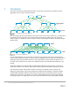
Due to increasing east-west traffic within the data center (server-server, server-storage, etc.), an alternative to
the traditional access-aggregation-core network model is becoming more widely used. This architecture,
shown in Figure 2, is known as a Clos or leaf-spine network and is designed to minimize the number of hops
between hosts.
Spine
Leaf
Leaf-spine architecture
In a leaf-spine architecture, the access layer is referred to as the leaf layer. Servers and storage devices
connect to leaf switches at this layer. At the next level, the aggregation and core layers are condensed into a
single spine layer. Every leaf switch connects to every spine switch to ensure that all leaf switches are no
more than one hop away from one another. This minimizes latency and the likelihood of bottlenecks in the
network.
A leaf-spine architecture is highly scalable. As administrators add racks to the data center, a pair of leaf
switches are added to each new rack. Spine switches may be added as bandwidth requirements increase.
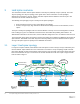
The connections between leaf and spine switches can be layer 2 (switched) or layer 3 (routed). This
deployment guide provides step-by-step configuration examples of both topologies. It includes examples
using Dell EMC Networking switches at both the leaf and spine layers and examples with Cisco Nexus
switches at the spine layer. The objective is to enable a network administrator or engineer with traditional
networking experience to deploy a layer 2 or layer 3 leaf-spine architecture using the examples provided.