
User's Manual

PRELIMINARY
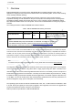
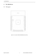
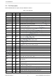
2. Pin Definitions
Name
No.
Type
Function
IO19
31
I/O
GPIO19, VSPIQ, U0CTS, EMAC_TXD0
NC
32
-
-
IO21
33
I/O
GPIO21, VSPIHD, EMAC_TX_EN
RXD0
34
I/O
GPIO3, U0RXD, CLK_OUT2
TXD0
35
I/O
GPIO1, U0TXD, CLK_OUT3, EMAC_RXD2
IO22
36
I/O
GPIO22, VSPIWP, U0RTS, EMAC_TXD1
IO23
37
I/O
GPIO23, VSPID, HS1_STROBE
GND
38
P
Ground
Notice:
* GPIO6 to GPIO11 are connected to the SPI flash integrated on the module and are not connected out.
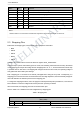
2.3 Strapping Pins
ESP32 has five strapping pins, which can be seen in Chapter 6 Schematics:
• MTDI
• GPIO0
• GPIO2
• MTDO
• GPIO5
Software can read the values of these five bits from register ”GPIO_STRAPPING”.
During the chip’s system reset release (power-on-reset, RTC watchdog reset and brownout reset), the latches
of the strapping pins sample the voltage level as strapping bits of ”0” or ”1”, and hold these bits until the chip
is powered down or shut down. The strapping bits configure the device’s boot mode, the operating voltage of
VDD_SDIO and other initial system settings.
Each strapping pin is connected to its internal pull-up/pull-down during the chip reset. Consequently, if a
strapping pin is unconnected or the connected external circuit is high-impedance, the internal weak pull-up/pull-
down will determine the default input level of the strapping pins.
To change the strapping bit values, users can apply the external pull-down/pull-up resistances, or use the host
MCU’s GPIOs to control the voltage level of these pins when powering on ESP32.
After reset release, the strapping pins work as normal-function pins.
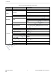
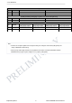
Refer to Table 4 for a detailed boot-mode configuration by strapping pins.
Table 4: Strapping Pins
Voltage of Internal LDO
(VDD_SDIO)
Pin
Default
3.3 V
1.8 V
MTDI
Pull-down
0
1
Espressif Systems 5 ESP32-WROOM-32E UserManual