-
User Guide Gateway 7001 Series Access Point
-
Contents 1 Introduction . . . . . . . . . . . . . . . . . . . . . . . . . . . . . . . . . . . . . . . . . . . . . . . . . . . . . . . . . . . . 1 Overview of the Gateway 7001 Series of self-managed APs . . . . . . . . . . . . . . . . . . . . . . . . 2 Features and benefits . . . . . . . . . . . . . . . . . . . . . . . . . . . . . . . . . . . . . . . . . . . . . . . . . . . . . . 3 Default settings and supported administrator/client platforms . . . . . . . . . . . . . . . . . . . . . . .
-
Cluster mode . . . . . . . . . . . . . . . . . . . . . . . . . . . . . . . . . . . . . . . . . . . . . . . . . . . . . . . . . Standalone mode . . . . . . . . . . . . . . . . . . . . . . . . . . . . . . . . . . . . . . . . . . . . . . . . . . . . . . Cluster formation . . . . . . . . . . . . . . . . . . . . . . . . . . . . . . . . . . . . . . . . . . . . . . . . . . . . . . Cluster size and membership . . . . . . . . . . . . . . . . . . . . . . . . . . . . . . . . . . . . . . . . . . . .
-
Enabling or disabling a network time protocol (NTP) server . . . . . . . . . . . . . . . . . . . . 79 Configuring network security . . . . . . . . . . . . . . . . . . . . . . . . . . . . . . . . . . . . . . . . . . . . . . . . 80 Understanding security issues on wireless networks . . . . . . . . . . . . . . . . . . . . . . . . . . 80 How do I know which security mode to use? . . . . . . . . . . . . . . . . . . . . . . . . . . . . . . . . 80 Navigating to security settings . . . . . . . . . . . . . . . . . .
-
A Glossary. . . . . . . . . . . . . . . . . . . . . . . . . . . . . . . . . . . . . . . . . . . . . . . . . . . . . . . . . . . . . . 175 B Specifications . . . . . . . . . . . . . . . . . . . . . . . . . . . . . . . . . . . . . . . . . . . . . . . . . . . . . . . . 197 C Safety, Regulatory, and Legal Information . . . . . . . . . . . . . . . . . . . . . . . . . . . 201 Index . . . . . . . . . . . . . . . . . . . . . . . . . . . . . . . . . . . . . . . . . . . . . . . . . . . . . . . . . . . . . . . . . . .
-
Chapter 1 Introduction ■ Features and benefits ■ Networking ■ Maintainability ■ Default settings and supported administrator/client platforms 1
-
Overview of the Gateway 7001 Series of self-managed APs The Gateway 7001 Series of self-managed APs (access points) provide continuous, high-speed access between your wireless and Ethernet devices. They are advanced, turnkey solutions for wireless networking in small and medium-sized businesses. The Gateway 7001 Series enables zero-administration wireless local area network (WLAN) deployment while providing state-of-the-art wireless networking features.
-
Features and benefits IEEE standards support and Wi-Fi compliance ■ Support for IEEE 802.11a, 802.11b, and 802.11g wireless networking standards (depending on model) ■ Provides bandwidth of up to 54 Mbps for 802.11a or 802.11g (11 Mbps for 802.11b, 108 Mbps for 802.11a Turbo) ■ Wi-Fi certified Wireless features ■ Auto channel selection at startup ■ Transmit power adjustment ■ Wireless Distribution System (WDS) for connecting multiple access points wirelessly.
-
Out-of-the-Box guest interface ■ Unique network name (SSID) for the Guest interface ■ Captive portal to guide guests to customized, guest-only Web page ■ VLAN and dual Ethernet options Clustering and auto-management ■ Automatic setup with Kickstart. ■ Provisioning and plug-and-play through automatic clustering and cluster rendezvous. The administrator can specify how new access points should be configured before they are added to the network.
-
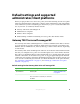
Default settings and supported administrator/client platforms Before you plug in and boot a new access point, review the following sections for a quick check of required hardware components, software, client configurations, and compatibility issues. Make sure you have everything you need ready to go for a successful launch and test of your new (or extended) wireless network.
-
Option Default Settings Related Information Password admin “Providing administrator password and wireless network name” on page 32 “Configuring security settings on wireless clients” on page 121 Network Name (SSID) “Gateway 7001 AP Network” for the Internal interface “Gateway 7001 AP Guest Network” for the Guest interface “Reviewing and describing the access point” on page 31 “Configuring internal LAN wireless settings” on page 76 “Configuring guest network wireless settings” on page 76 Network Tim
-
Option Default Settings Related Information IEEE 802.11 Mode 802.11g pr 802.11a+g “Configuring radio settings” on page 104 802.
-
Option Default Settings Related Information MAC Filtering Allow any station unless in list “Controlling access by MAC address filtering” on page 110 Guest Login Disabled “Advanced Configuration” on page 67 Guest Welcome Screen Text Thank you for using wireless Guest Access as provided by this Gateway 7001 Series wireless access point.
-
Administrator’s computer Configuration and administration of the Gateway 7001 Series self-managed AP is accomplished with the KickStart utility (which you run from the CD) and through a Web-based user interface (UI). The following table describes the minimum requirements for the administrator’s computer.
-
Required Software or Component Description KickStart Wizard on You can run the KickStart CD on any laptop or computer that is connected to the access point (through Wired or Wireless connection). It detects Gateway 7001 Series self-managed APs on the network. The wizard steps you through initial configuration of new access points, and provides a link to the Administration Web pages where you finish up the basic setup process in a step-by-step mode and launch the network.
-
Wireless client computers The Gateway 7001 Series self-managed AP provides wireless access to any client with a correctly configured Wi-Fi client adapter for the 802.11 mode in which the access point is running. Multiple client operating systems are supported. Clients can be laptops or desktops, personal digital assistants (PDAs), or any other hand-held, portable or stationary device equipped with a Wi-Fi adapter and supporting drivers.
-
Understanding dynamic and static IP addressing Gateway 7001 Series self-managed APs are built to auto-configure, with very little setup required for the first access point and no configuration required for additional access points subsequently joining a preconfigured cluster. How does the access point obtain an IP address at startup? When you deploy the access point, it looks for a network DHCP server and, if it finds one, obtains an IP Address from the DHCP server.
-
Static IP addressing The Gateway 7001 Series self-managed AP ships with a default Static IP Address of 192.168.1.1. (See the default settings for the AP in “Gateway 7001 Series self-managed AP” on page 5.) If no DHCP server is found on the network, the AP retains this static IP address at first-time startup.
-
14 www.gateway.
-
Chapter 2 Quick Setup ■ Unpacking the access point ■ Connecting the access point to network and power ■ Turning on the access point ■ Running KickStart to find access points and assign IP addresses ■ Configuring basic settings and starting the wireless network 15
-
Setting up the access point Setting up and deploying one or more Gateway 7001 Series self-managed APs is in effect creating and launching a wireless network. The KickStart Wizard and corresponding Basic Settings Administration Web page simplify this process. Here is a step-by-step guide to setting up your Gateway 7001 Series self-managed APs and the resulting wireless network.
-
What’s inside the access point? An access point is a single-purpose computer designed to function as a wireless hub. Inside the access point is a Wi-Fi radio system, a microprocessor, and sometimes a mini-PC card. The access point boots from FlashROM that contains firmware with the configurable, runtime features summarized in “Overview of the Gateway 7001 Series of self-managed APs” on page 2.
-
Connecting the access point to network and power The next step is to set up the network and power connections. To set up the network and power connections: 1 Connect one end of an Ethernet cable to the network port on the access point and the other end to the same hub where your computer is connected.
-
Important If you use a hub, the device you use must permit broadcast signals from the access point to reach all other devices on the network. A standard hub should work fine. Some switches, however, do not allow directed or subnet broadcasts through. You may have to configure the switch to allow directed broadcasts.
-
Hardware connections for a physically separate guest network If you plan to configure a physically separate guest network, you need to set up your network connections differently at this point. The Gateway 7001 Series self-managed AP ships with an extra network port to support configuration of a physically separate guest network.
-
Important Keep in mind that KickStart (and the other Gateway administration tools) recognizes and configures only Gateway 7001 Series self-managed APs. KickStart will not find or configure other kinds of access points or other devices. Run Kickstart only in the subnet of the “Internal” network (SSID). Do not run Kickstart on the guest subnetwork. Kickstart will find only those access points that have IP addresses.
-
To run KickStart: 1 22 Insert the KickStart Wizard CD into the CD drive on your computer. If the KickStart window is not displayed automatically, navigate to the CD drive and double-click the Kickstart executable file to activate the KickStart utility on the CD. The KickStart Welcome screen is displayed. www.gateway.
-
2 Click Next to search for access points. Wait for the search to complete, or until KickStart has found your new access points. Important 3 If no access points are found, Kickstart indicates this and presents some troubleshooting information about your LAN and power connections. After you have checked hardware power and Ethernet connections, you can click the Kickstart Back button to search again for access points. Review the list of access points found.
-
Important KickStart provides a link to the Administration Web pages through the IP address of the first access point. The Administration Web pages are a centralized management tool that you can access through the IP address for any access point in a cluster. After your other access points are configured, you can also link to the Administration Web pages by using the IP address for any of the other Gateway access points in a URL (http://IPAddressOfAccessPoint).
-
Type the user name and password and click OK. www.gateway.
-
Viewing basic settings for Gateway 7001 Series self-managed access points When you log in, the Basic Settings page for Gateway 7001 Series self-managed AP administration is displayed. These are global settings for all access points that are members of the cluster and, if automatic configuration is specified, for any new access points that are added later. 26 www.gateway.
-
Configuring basic settings and starting the wireless network Provide a minimal set of configuration information by defining the basic settings for your wireless network. These settings are all available on the Basic Settings page of the Administration Web interface, and are categorized into steps 1-4 on the Web page. To configure the basic settings: 1 Review the description of this access point and provide IP addressing information.
-
What’s next? Make sure the access point is connected to the LAN and access some wireless clients. After you have tested the basics of your wireless network, you can enable more security and fine-tune by modifying advanced configuration features. Make sure the access point is connected to the LAN If you configured the access point and administrator computer by connecting both into a network hub, then your access point is already connected to the LAN. The next step is to test some wireless clients.
-
Chapter 3 Configuring Basic Network Settings ■ Navigating to basic settings ■ Reviewing and describing the access point ■ Setting configuration policy for new access points ■ Understanding basic settings for a standalone access point ■ Understanding indicator icons 29
-
Navigating to basic settings To configure basic Network settings, click Network, then click Basic Settings. If you use Kickstart to link to the Administration Web pages, the Basic Settings page is displayed by default. Fill in the boxes on the Basic Settings page as described in the following section. 30 www.gateway.
-
Reviewing and describing the access point Field Action IP Address This box is not editable because the IP address is already assigned (either through DHCP, or statically through the Ethernet (Wired) settings as described in “Configuring Guest interface Ethernet settings” on page 73). MAC Address A MAC address is a permanent, unique hardware address for any device that represents an interface to the network. The MAC address is assigned by the manufacturer. You cannot change the MAC address.
-
Providing administrator password and wireless network name Caution The Gateway 7001 Series self-managed AP is not designed for multiple, simultaneous configuration changes. If you have a network that includes multiple access points, and more than one administrator is logged on to the Administration Web pages and making changes to the configuration, all access points in the cluster will stay in synch but there is no guarantee that all configuration changes specified by multiple users will be applied.
-
Field Action Wireless Network Name (SSID) Type a name for the wireless network as a character string. This name will apply to all access points on this network. As you add more access points, they will share this SSID. The Service Set Identifier (SSID) is an alphanumeric string of up to 32 characters Note: If you are connected as a wireless client to the same AP that you are administering, resetting the SSID will cause you to lose connectivity to the AP.
-
Setting configuration policy for new access points 34 www.gateway.
-
Field Action New Access Points Choose the policy you want to put in effect for adding New Access Points to the network. • If you choose are configured automatically, then when a new access points is added to the network it automatically joins the existing cluster. The cluster configuration is copied to the new access point, and no manual configuration is required to deploy it. • If you choose are ignored, new access points will not join the cluster, but will be considered standalone.
-
Updating basic settings When you have reviewed the new configuration, click Update to apply the settings and deploy the access points as a wireless network. 36 www.gateway.
-
Understanding basic settings for a standalone access point The Basic Settings tab for a standalone access point indicates only that the current mode is standalone and provides a button for adding the access point to a cluster (group). If you click on any of the Cluster tabs on the Administration pages for an access point in standalone mode, you will be re-directed to the Basic Settings page because Cluster settings do not apply to standalone APs.
-
Understanding indicator icons All the network settings tabs on the Administration Web pages include visual indicator icons showing current network activity Icon Description The clustering icon indicates whether the current access point is “Clustered” or “Not Clustered” (that is, standalone). The number of access points available for service on this network is indicated by the “Access Points” icon.
-
Chapter 4 Managing Access Points and Clusters ■ Navigating to access points management ■ Understanding clustering and access points ■ Modifying the location description ■ Adding and removing an access point ■ Navigating to an AP by using its IP address in a URL 39
-
Introduction The Gateway 7001 Series self-managed APs show current basic configuration settings for clustered access points (location, IP address, MAC address, status, and availability) and provide a way of navigating to the full configuration for specific APs if they are cluster members. Standalone access points (those which are not members of the cluster) do not show up in this listing.
-
Navigating to access points management To view or edit information on access points in a cluster, click Cluster > Access Points on the Administration Web page. The Manage access points in the cluster screen opens. www.gateway.
-
Understanding clustering A key feature of the Gateway 7001 Series self-managed AP is the ability to form a dynamic, configuration-aware group (called a cluster) with other Gateway access points in a network in the same subnet. Access points can participate in a peer-to-peer cluster which makes it easier for you to deploy, administer, and secure your wireless network.
-
Having a mix of APs on the network does not adversely affect Gateway 7001 Series self-managed AP clustering in any way, however it is helpful to understand the clustering behavior for administration purposes: ■ Gateway 7001 Series self-managed APs of the same model will form a cluster. The dual-band APs will form one cluster and the single-band APs will form another cluster. ■ Non-Gateway APs will not join Gateway clusters.
-
Settings that are not shared must be configured individually on the Administration pages for each access point. To get to the Administration pages for an access point that is a member of the current cluster, click on its IP Address link on the Cluster > Access Points page of the current AP. Cluster mode When an access point is a cluster member, it is considered to be in cluster mode.
-
You can re-enable cluster mode on a standalone access point. (See “Adding an access point to a cluster” on page 52.) Cluster formation A cluster is formed when the first Gateway 7001 Series self-managed AP is configured. (See “Quick Setup” on page 15 and “Configuring Basic Network Settings” on page 29.) If a cluster configuration policy is in place when a new access point is deployed, it attempts to rendezvous with an existing cluster.
-
Note that auto-synchronization always occurs during configuration updates that affect the cluster, but the processing time is usually negligible. The auto-synch progress bar is displayed only for longer-than-usual wait times. Cluster recovery In cases where the access points in a cluster become out of sync for any of the reasons mentioned in “Known problems” on page 172, or an access point cannot join or be removed from a cluster, the following methods for cluster recovery are recommended.
-
The Stop Clustering page for this access point opens. 2 3 Click the Stop Clustering button. Repeat steps 1 and 2 for every access point in the cluster. Caution 4 Do not proceed to the next step of resetting any access points until you have stopped clustering on all of them. Make sure that you first “Stop Clustering” on every access point on the subnet, and only then perform the next part of the process of resetting each one to the factory defaults.
-
5 On the Administration UI left-hand tabs, click Advanced > Reset Configuration to open the Reset page. The Reset page opens. 6 Click Reset to restore the factory defaults on the access point. (This will clear all of your previous settings, including updated passwords.) 7 Repeat steps 4 through 6 for every access point in the cluster. Caution 48 Do not proceed to the next step until you have stopped clustering on all of access points in the pre-existing cluster. www.gateway.
-
8 Refresh the cluster view by clicking Cluster > Access Points on the Administration Web pages for any one of the access points. The Access Points cluster management page opens. 9 Click Refresh. At this point you should see all previous cluster members displayed in the list. Before proceeding to the last step, verify that the cluster has reformed by making sure all are access points are listed. 10 Review all configuration settings and make modifications as needed.
-
Understanding access point settings The Access Points tab on the Administration Web page provides information about all access points on the wireless network. From this tab, you can view location descriptions, IP addresses, enable (activate) or disable (deactivate) clustered access points, and remove access points from the cluster. You can also modify the location description for an access point. The IP address links provide a way to navigate to configuration settings and data on an access point.
-
Working with access points in a cluster Modifying the location description To make modifications to the location description: 1 2 Click Basic Settings on the Administration Web page. 3 Click Update to apply the changes. Update the location description in section 1 under “Review Description of this Access Point.” Removing an access point from the cluster To remove an access point from the cluster: 1 Click Cluster > Access Points on the Administration Web page.
-
Adding an access point to a cluster To add an access point that is currently in standalone mode back into a cluster: 1 Go to the Administration Web pages for the standalone access point. (See “Navigating to an AP by using its IP address in a URL” on page 53.) The Administration Web page for the standalone access point is displayed. 2 Click the Basic Settings tab in the Administration pages for the standalone access point.
-
Navigating to information for a specific AP and managing standalone APs In general, Gateway 7001 Series self-managed APs are designed for central management of clustered access points. For access points in a cluster, all access points in the cluster reflect the same configuration. In this case, it does not matter which access point you actually connect to for administration. There may be situations, however, when you want to view or manage information on a particular access point.
-
54 www.gateway.
-
Chapter 5 Managing User Accounts ■ Navigating to user management for clustered access points ■ Viewing and changing user accounts ■ Adding a user ■ Editing a user accountt ■ Enabling and disabling user accounts ■ Removing a user 55
-
Introduction The Gateway 7001 Series self-managed APs include user management capabilities for controlling client access to access points. User management and authentication must always be used in conjunction with the following two security modes, which require use of a RADIUS server for user authentication and management. ■ IEEE 802.1x mode (see “IEEE 802.
-
Navigating to user management for clustered access points To set up or modify user accounts, click Cluster > User Management on the Administration Web page. The Manage user accounts screen opens. www.gateway.
-
Viewing and changing user accounts Viewing user accounts User accounts are shown at the top of the Manage user accounts screen under User Accounts. User name, real name and status (enabled or disabled) are shown. You can make modifications to an existing user account by first selecting the checkbox next to a user name then choosing an action.
-
Editing a user account After you have created a user account, it is displayed under User Accounts at the top of the User Management Web page. To make modifications to an existing user account, first click the checkbox next to the user name so that a checkmark is displayed in the box. Then, choose an action such as Edit, Enable, Disable, or Remove. Enabling and disabling user accounts A user account must be enabled for the user to log on as a client and use the access point.
-
To disable a user account: ■ On the User Management Web page, under User Accounts, click the box next to the user name, then click Disable. A user with an account that is disabled cannot log on to the wireless access points in your network as a client. However, the user remains in the database and can be enabled later as needed. To remove a user account: ■ On the User Management Web page, under User Accounts, click the box next to the user name, then click Remove.
-
Chapter 6 Session Monitoring ■ Navigating to session monitoring ■ Understanding session monitoring information ■ Viewing session information for access points ■ Sorting session information ■ Refreshing session information 61
-
Navigating to session monitoring To view session monitoring information, click Cluster > Sessions on the Administration Web page. The Monitor active client station sessions page opens. 62 www.gateway.
-
Understanding session monitoring information The Monitor active client station sessions page shows the stations associated with access points in the cluster. A session in this context is the period of time in which a user on a client device (station) with a unique MAC address maintains a connection with the wireless network. The session begins when the client logs on to the network, and the session ends when the client either logs off intentionally or loses the connection for some other reason.
-
Field Description Signal Indicates the strength of the radio frequency (RF) signal the client receives from the access point. The measure used for this is an IEEE 802.1x value known as Received Signal Strength Indication (RSSI), and will be a value between 0 and 100. RSSI is determined by a an IEEE 802.1x mechanism implemented on the network interface card (NIC) of the client station. Utilization Utilization rate for this station.
-
Viewing session information for access points You can view session information for all access points on the network at the same time, or set the display to show session information for a specified access point chosen from the list at the top of the screen. To view information on all access points, select the Show all access points option at the top of the page.
-
66 www.gateway.
-
Chapter 7 Advanced Configuration ■ Configuring an Ethernet (wired) interface ■ Configuring a wireless interface ■ Configuring network security ■ Configuring radio settings 67
-
Configuring an Ethernet (wired) interface Ethernet (Wired) Settings describe the configuration of your Ethernet local area network (LAN) Caution 68 The Ethernet Settings, including Guest Access, are not shared across the cluster. These settings must be configured individually on the Administration pages for each access point. To get to the Administration pages for an access point that is a member of the current cluster, click on its IP Address link on the Cluster > Access Points page of the current AP.
-
Navigating to Ethernet (wired) settings To set the wired address for an access point, Advanced > Ethernet (Wired) Settings on the Administration Web page, and update the boxes as described in the following section. Setting the DNS name Field Description DNS Name Type a DNS name for the access point in the text box. This is the host name. It may be provided by your ISP or network administrator, or you can provide your own. The rules for system names are: • This name can be up to 20 characters long.
-
Enabling or Disabling Guest Access You can provide controlled guest access over an isolated network and a secure internal LAN on the same Gateway 7001 Series self-managed AP. Configuring an internal LAN and a guest network A Local Area Network (LAN) is a communications network covering a limited area, for example, one floor of a building. A LAN connects multiple computers and other network devices like storage and printers. Ethernet is the most common technology implementing a LAN.
-
Choose either physically separate or virtually separate internal and guest LANs as described in the following section. Field Description For Internal and Guest access, use two Specify either a physically or virtually separate guest network on this access point: ■ ■ Caution If you connected this access point to two separate networks for a “physically secure” solution, then choose Ethernet Ports from the list. (Choosing “Ethernet Ports” here will disable the “VLAN” settings.
-
Field Connection Type Description You can select “DHCP Client” or “Static IP”. The Dynamic Host Configuration Protocol (DHCP) is a protocol specifying how a centralized server can provide network configuration information to clients. A DHCP server “offers” a “lease” to the client system. The information supplied includes the client's IP addresses and net mask plus the address of its DNS servers and gateway. Static IP indicates that all network settings are provided manually.
-
Configuring Guest interface Ethernet settings To configure Ethernet (Wired) settings for the “Guest” interface, fill in the boxes as described in the following table. Field Description MAC Address Shows the MAC address for the guest interface for this access point. This is a read-only box that you cannot change. VLAN ID If you choose to configure internal and guest networks by “VLANs”, this box will be enabled. Provide a number between 1 and 4094 for the guest VLAN.
-
Configuring a wireless interface Navigating to wireless settings To set the wireless address for an access point, click Advanced > Wireless Settings on the Administration Web page, and update the boxes as described in the following section. Important The following illustration shows the Wireless settings page for the dual band AP (Gateway 7001 802.11 A+G Wireless Access Point). The Administration Web page for the single band AP (Gateway 7001 802.11 G Wireless Access Point) will look slightly different.
-
Field Description MAC Addresses (Shown on dual-band AP only) Indicates the Media Access Control (MAC) addresses for the interface. On the dual band AP only, the MAC addresses for Radio Interface One (Internal/Guest) and Radio Interface Two (Internal/Guest) are shown. A MAC address is a permanent, unique hardware address for any device that represents an interface to the network. The MAC address is assigned by the manufacturer. You cannot change the MAC address.
-
Configuring internal LAN wireless settings The internal settings describe the MAC Address (read-only) and Network Name (also known as the SSID) for the internal Wireless LAN (WLAN) as described in the following section. Field Description MAC Address Shows the MAC address for internal interface for this access point. This is a read only box that you cannot change. Although this access is point is physically a single device, it is represented on the network as two nodes each with a unique MAC Address.
-
Field SSID Description Type the SSID for the internal WLAN. The Service Set Identifier (SSID) is an alphanumeric string of up to 32 characters that uniquely identifies a wireless local area network. It is also referred to as the Network Name. There are no restrictions on the characters that may be used in an SSID. For the guest network, provide an SSID that is different from the internal SSID and easily identifiable as the guest network. Updating settings To apply your changes, click Update. www.gateway.
-
Enabling a network time protocol server The Network Time Protocol (NTP) is an Internet standard protocol that synchronizes computer clock times on your network. NTP servers transmit Coordinated Universal Time (UTC, also known as Greenwich Mean Time) to their client systems. NTP sends periodic time requests to servers, using the returned time stamp to adjust its clock. The timestamp will be used to indicate the date and time of each event in log messages. See http://www.ntp.
-
Enabling or disabling a network time protocol (NTP) server To configure your access point to use a network time protocol (NTP) server, first enable the use of NTP, then select the NTP server you want to use. (To shut down NTP service on the network, disable NTP on the access point.) Field Description Network Time Protocol NTP provides a way for the access point to obtain and maintain its time from a server on the network.
-
Configuring network security Understanding security issues on wireless networks Wireless mediums are inherently less secure than wired mediums. For example, an Ethernet NIC transmits its packets over a physical medium such as coaxial cable or twisted pair. A wireless NIC broadcasts radio signals over the air allowing a wireless LAN to be easily tapped without physical access or sophisticated equipment.
-
Comparison of security modes for key management, authentication, and encryption algorithms The three major factors that determine the effectiveness of a security protocol are: ■ How the protocol manages keys ■ Presence or absence of integrated user authentication in the protocol ■ Encryption algorithm or formula the protocol uses to encode/decode the data Following is a list of the security modes available on the Gateway 7001 Series self-managed AP along with a description of the key management, authe
-
Key Management Encryption Algorithm User Authentication Static WEP uses a fixed key that is provided by the administrator. WEP keys are indexed in different slots (up to four on the Gateway 7001 Series self-managed AP). An RC4 stream cipher is used to encrypt the frame body and cyclic redundancy checking (CRC) of each 802.11 frame. If you set the Authentication Algorithm to Shared Key, this protocol provides a rudimentary form of user authentication.
-
Key Management Encryption Algorithm User Authentication IEEE 802.1x provides dynamically generated keys that are periodically refreshed. An RC4 stream cipher is used to encrypt the frame body and cyclic redundancy checking (CRC) of each 802.11 frame. There are different Unicast keys for each station. (This is the same encryption algorithm as is used for Static WEP.) IEEE 802.
-
Key Management Encryption Algorithm User Authentication WPA with RADIUS provides dynamically-generated keys that are periodically refreshed. • Temporal Key Integrity Protocol (TKIP) Remote Authentication Dial-In User Service (RADIUS) • Counter mode/CBC-MAC Protocol (CCMP) Advanced Encryption Standard (AES) You have a choice of using the Gateway 7001 Series self-managed AP embedded RADIUS server or an external RADIUS server. The embedded RADIUS server supports Protected EAP (PEAP) and MSCHAP V2.
-
Important If there are older client stations on your network that do not support WPA, you can configure WPA with RADIUS (with Both, CCMP, or TKIP) and check the Allow non-WPA IEEE 802.1x clients checkbox to allow non-WPA clients. This way, you get the benefit of IEEE 802.1x key management for non-WPA clients along with even better data protection of TKIP and CCMP (AES) key management and encryption algorithms for your WPA clients. A typical scenario is that one is upgrading a current 802.
-
For example, some devices on your network may not support WPA with EAP talking to a RADIUS server. Embedded printer servers or other small client devices with very limited space for implementation may not support RADIUS. For such cases, we recommend that you use WPA-PSK. For information on how to configure WPA-PSK security mode, see “WPA-PSK” on page 97.
-
Navigating to security settings To set the security mode, click Advanced > Security on the Administration Web page. The Modify security settings that apply to the internal network screen opens. Update the boxes as described in the following section. Configuring security settings The following configuration information explains how to configure security modes on the access point.
-
Broadcast SSID and Security Mode To configure security on the access point, select a security mode and fill in the related boxes as described in the following table. (Note you can also allow or prohibit the Broadcast SSID as an extra precaution as mentioned in the following section.) Field Broadcast SSID Description Select the Broadcast SSID setting by clicking the Allow or Prohibit option. By default, the access point broadcasts the Service Set Identifier (SSID) in its beacon frames.
-
For a minimum level of protection on a guest network, you can choose to suppress (prohibit) the broadcast of the SSID (network name) to discourage client stations from automatically discovering your access point. (See also “Does Prohibiting the Broadcast SSID Enhance Security?” on page 86.) (For more about the guest network, see “Setting up Guest Access” on page 99.) Static WEP Wired Equivalent Privacy (WEP) is a data encryption protocol for 802.11 wireless networks.
-
Field Description Transfer Key Index Select a key index from the list. Key indexes 1 through 4 are available. The default is 1. The Transfer Key Index indicates which WEP key the access point will use to encrypt the data it transmits. Key Length Specify the length of the key by clicking one of the options: • 64 bits • 128 bits Key Type Select the key type by clicking one of the options: • ASCII • Hex Characters Required Indicates the number of characters required in the WEP key.
-
Field Description Authentication Algorithm The authentication algorithm defines the method used to determine whether a client station is allowed to associate with an access point when static WEP is the security mode. Specify the authentication algorithm you want to use by choosing one of the following from the list: • Open System • Shared Key • Both Open System authentication lets any client station associate with the access point whether that client station has the correct WEP key or not.
-
Example of Using Static WEP For a simple example, suppose you configure three WEP keys on the access point. In our example, the Transfer Key Index for the AP is set to 3. This means that the WEP key in slot 3 is the key the access point will use to encrypt the data it sends. You must then set all client stations to use WEP and provide each client with one of the slot/key combinations you defined on the AP. For this example, we will set WEP Key index to 1 on a Windows client. 92 www.gateway.
-
If you have a second client station, that station also needs to have one of the WEP keys defined on the AP. You could give it the same WEP key you gave to the first station. Or for a more secure solution, you could give the second station a different WEP key (key 2, for example) so that the two stations cannot decrypt each other’s transmissions.
-
When configuring IEEE 802.1x mode, you have a choice of whether to use the embedded RADIUS server or an external RADIUS server that you provide. The Gateway 7001 Series self-managed AP embedded RADIUS server supports Protected EAP (PEAP) and MSCHAP V2. If you use your own RADIUS server, you have the option of using any of a variety of authentication methods that the IEEE 802.1x mode supports, including certificates, Kerberos, and public key authentication.
-
Field Description Enable RADIUS Accounting Click Enable RADIUS Accounting if you want to track and measure the resources a particular user has consumed such as system time, amount of data transmitted and received, and so on. WPA with RADIUS Wi-Fi Protected Access (WPA) with Remote Authentication Dial-In User Service (RADIUS) is a Wi-Fi Alliance subset of IEEE 802.11i, which includes Temporal Key Integrity Protocol (TKIP), Counter mode/ CBC-MAC Protocol (CCMP) Advanced Encryption Standard (AES), and 802.
-
Field Description Cipher Suites Select the cipher you want to use from the list: • TKIP • CCMP (AES) • Both Temporal Key Integrity Protocol (TKIP) is the default. TKIP provides a more secure encryption solution than WEP keys. The TKIP process more frequently changes the encryption key used and better ensures that the same key will not be re-used to encrypt data (a weakness of WEP). TKIP uses a 128-bit “temporal key” shared by clients and access points.
-
Field Radius IP Description Type the Radius IP in the text box. The Radius IP is the IP address of the RADIUS server. The RADIUS IP address for the Gateway 7001 Series self-managed AP internal authentication server is 127.0.0.1. This will be provided automatically if you selected the built-in authentication server. For information on setting up user accounts, see “Managing User Accounts” on page 55. Radius Key Type the Radius Key in the text box.
-
Field Cipher Suites Description Select the cipher you want to use from the list: • TKIP • CCMP (AES) • Both Temporal Key Integrity Protocol (TKIP) is the default. TKIP provides a more secure encryption solution than WEP keys. The TKIP process more frequently changes the encryption key used and better ensures that the same key will not be re-used to encrypt data (a weakness of WEP). TKIP uses a 128-bit “temporal key” shared by clients and access points.
-
Setting up Guest Access Out-of-the-box guest interface features allow you to configure the Gateway 7001 Series self-managed AP for controlled guest access to an isolated network. You can configure the same access point to broadcast and function as two different wireless networks: a secure Internal LAN and a public Guest network. Guest clients can access the guest network without a user name or password. When guests log in, they see a guest welcome screen (also known as a captive portal).
-
Configuring the guest interface To configure the Guest interface: 1 Do one of the following: Configure the access point to represent two physically separate networks as described in the following section, see “Configuring a physically separate guest network” on page 100. OR Configure the access point to represent two virtually separate networks as described in the following section, see “Configuring a guest network on a virtual LAN” on page 101.
-
(Start by choosing For Internal and Guest access, use two: Ethernet Ports as described in “Specifying a physical or virtual Guest network” on page 70.) 3 Provide the radio interface settings and network names (SSIDs) for both internal and guest networks as described in “Configuring a wireless interface” on page 74. 4 Configure other settings on the access point as needed (not necessarily specific to the guest network) as described in this guide.
-
To set up the captive portal: 1 Click Advanced > Guest Login on the Administration Web page. The Modify guest welcome screen settings screen opens. 2 3 Choose Enabled to activate the welcome screen. 4 In the Welcome Screen Text box, type the text message you would like guest clients to see on the captive portal. Click Update to apply the changes. Using the guest network as a client After the guest network is configured, a client can access the guest network.
-
3 The guest client chooses Guest SSID. The guest client starts a Web browser and receives a Guest Welcome Screen. The Guest Welcome Screen provides a button for the client to click to continue. The guest client can now use the “guest” network. Deployment example In the figure, the dotted red lines indicate dedicated guest connections. All access points and all connections (including guests) are administered from the same Gateway 7001 Series self-managed AP Administration Web pages.
-
Configuring radio settings Understanding radio settings Radio settings directly control the behavior of the radio device in the access point and its interaction with the physical medium, specifically how and what type of electromagnetic waves the AP emits. You can specify whether the radio is on or off, radio frequency (RF) broadcast channel, beacon interval (amount of time between AP beacon transmissions), transmit power, IEEE 802.11 mode in which the radio operates, and so on.
-
Navigating to radio settings To specify radio settings, click Advanced > Radio on the Administration Web page. The Modify radio settings screen opens. Update the boxes as described in the following section. www.gateway.
-
Configuring radio settings Field Description Radio The Gateway 7001 Series self-managed AP is available in a dual band and single band version. Single-Band AP: If you have the single band version of the Gateway 7001 AP, this box is not included on the Radio tab. Dual-Band AP: The dual band access point capable of broadcasting in two different IEEE 802.11 modes simultaneously. • Radio One runs in IEEE 802.11b and IEEE 802.11g modes. • Radio Two runs in IEEE 802.11a and IEEE 802.11a Turbo modes.
-
Field Description Beacon Interval Beacon frames are transmitted by an access point at regular intervals to announce the existence of the wireless network. The default behavior is to send a beacon frame once every 100 milliseconds (or 10 per second). The Beacon Interval value is set in milliseconds. Type a value from 20 to 2000. DTIM Period The Delivery Traffic Information Map (DTIM) message is an element included in some Beacon frames.
-
Field RTS Threshold Description Specify an RTS Threshold value between 0 and 2347. The RTS threshold specifies the packet size of a request to send (RTS) transmission. This helps control traffic flow through the access point, especially one with a lot of clients. If you specify a low threshold value, RTS packets will be sent more frequently. This will consume more bandwidth and reduce the throughput of the packet.
-
Updating settings To apply your changes, click Update. Important If you are using the dual band version of the Gateway 7001 Series self-managed AP, keep in mind that both Radio One and Radio Two are configured on this tab. The displayed settings apply to either Radio One or Radio Two, depending on which radio you choose in the Radio box (the first box on the tab). When you have configured settings for one of the radios, click Update, then select and configure the other radio.
-
Controlling access by MAC address filtering A Media Access Control (MAC) address is a hardware address that uniquely identifies each node of a network. All IEEE 802 network devices share a common 48-bit MAC address format, usually displayed as a string of 12 hexadecimal digits separated by colons, for example FE:DC:BA:09:87:65. Each wireless network interface card (NIC) used by a wireless client has a unique MAC address.
-
Using MAC address filtering This page lets you control access to Gateway 7001 Series self-managed AP based on Media Access Control (MAC) addresses. Based on how you set the filter, you can allow only client stations with a listed MAC address or prevent access to the stations listed. For the guest interface, MAC filtering settings apply to both BSSes.
-
Configuring a Wireless Distribution System (WDS) The Gateway 7001 Series self-managed AP lets you connect multiple access points using a Wireless Distribution System (WDS). WDS lets access points communicate with one another wirelessly in a standardized way. This capability is critical in providing a seamless experience for roaming clients and for managing multiple wireless networks. It can also simplify the network infrastructure by reducing the amount of cabling required.
-
Conference Room (LAN 1), and another Ethernet-wired access point serving stations in the West Wing offices (LAN 2). You can bridge the Conference Room and West Wing access points with a WDS link to create a single network for clients in both areas.
-
by placing a second access point closer to second group of stations (“Poolside” in our example) and bridge the two APs with a WDS link. This extends your network wirelessly by providing an extra hop to get to distant stations.
-
Security considerations related to WDS bridges Static Wired Equivalent Privacy (WEP) is a data encryption protocol for 802.11 wireless networks. Both access points in a given WDS link must be configured with the same security settings. For static WEP, either a static 64-bit (40-bit secret key + 24-bit initialization vector (IV)) or 128-bit (104-bit secret key + 24-bit IV) Shared Key is specified for data encryption. You can enable Static WEP on the WDS link (bridge).
-
Important 116 The following figure shows the WDS settings page for the dual band AP (Gateway 7001 802.11 A+G Wireless Access Point). The Administration Web page for the single band AP (Gateway 7001 802.11 G Wireless Access Point) will look slightly different. www.gateway.
-
Configuring WDS settings The following notes summarize some critical guidelines regarding WDS configuration. Read all the notes before proceeding with WDS configuration. Important • The only security mode available on the WDS link is Static WEP, which is not particularly secure. Therefore, we recommend using WDS to bridge the guest network only for this release.
-
Field Description Radio The Gateway 7001 AP is available in a dual band and single band version. Single-Band AP: On the single band version of the Gateway® 7001 AP, this box is not included on the WDS tab. Dual-Band AP: For each WDS link on a dual-band AP, select Radio One or Radio Two. The rest of the settings for the link apply to the radio selected in this box. The read-only “Local Address” will change depending on which Radio you select here.
-
Field Description WEP Specify whether you want Wired Equivalent Privacy (WEP) encryption enabled for the WDS link. • Enabled • Disabled Wired Equivalent Privacy (WEP) is a data encryption protocol for 802.11 wireless networks. Both access points on the WDS link must be configured with the same security settings. For static WEP, a static 64-bit (40-bit secret key + 24-bit initialization vector (IV)) or 128-bit (104-bit secret key + 24-bit IV) Shared Key for data encryption.
-
3 Configure a WDS interface for data exchange with MyAP2 (for example). Start by typing the MAC address for MyAP2 as the “Remote Address” and fill in the rest of the boxes to specify the network (guest or internal), security, and so on. Save the settings (click Update). 4 Click Advanced—>Radio on the Administration Web page to verify or set the mode and the radio channel on which you want MyAP1 to broadcast.
-
Configuring security settings on wireless clients Typically, users will configure security on their wireless clients for access to many different networks (access points). The list of “Available Networks” will change depending on the location of the client and which APs are online and detectable in that location. The exception to this is if the access point is set to prohibit the broadcast of its network name. In this case the SSID will not show up in the list of Available Networks on the client.
-
■ “Configuring a client to access an unsecure network (plain text mode)” on page 125 ■ “Configuring static WEP security on a client” on page 126 ■ “Configuring IEEE 802.
-
■ “IEEE 802.1x client using EAP-TLS certificate” on page 133 ■ “WPA with RADIUS client using EAP-TLS certificate” on page 141 ■ “Configuring an external RADIUS server to recognize the Gateway 7001 AP” on page 146 ■ “Obtaining a TLS-EAP certificate for a client” on page 151 Details on how to configure an EAP-PEAP client with an external RADIUS server are not covered in this document.
-
d Select the SSID of the network to which you want to connect, then click Advanced. The Wireless Network Connection Properties dialog box, which lists available networks and preferred networks, opens. The list of available networks will change depending on client location. Each network (or access point) that is detected by the client shows up in this list. (“Refresh” updates the list with current information.
-
Use this dialog box for configuring all the different types of client security described in the following sections. Make sure that the Wireless Network Properties dialog box you are working in pertains to the Network Name (SSID) for the network you want to reach on the wireless client you are configuring.
-
Configuring static WEP security on a client Static Wired Equivalent Privacy (WEP) encrypts data moving across a wireless network based on a static (non-changing) key. The encryption algorithm is a “stream” cipher called RC4. The access point uses a key to transmit data to the client stations. Each client must use that same key to decrypt data it receives from the access point. Different clients can use different keys to transmit data to the access point.
-
To configure WEP security on each client: 1 On the Network Properties dialog box, select the Association tab. The Association dialog box opens. 2 Select Open or Shared in the Network Authentication list, then select WEP in the Data encryption list. 3 Type a Network key in the box provided. Make sure the network key matches the WEP key on the access point in the position selected to the Key index (advanced). Retype to confirm.
-
Association Tab Network Authentication Open or Shared, depending on how you configured this option on the access point. Note: When the Authentication Algorithm on the access point is set to Both, clients set to either Shared or Open can associate with the AP. Clients configured to use WEP in Shared mode must have a valid WEP key in order to associate with the AP.
-
Configuring IEEE 802.1x security on a client IEEE 802.1x is the standard defining port-based authentication and infrastructure for doing key management. Extensible Authentication Protocol (EAP) messages are sent over an IEEE 802.11 wireless network using a protocol called EAP Encapsulation Over LANs (EAPOL). IEEE 802.1x provides dynamically-generated keys that are periodically refreshed. An RC4 stream cipher is used to encrypt the frame body and cyclic redundancy checking (CRC) of each 802.11 frame.
-
To configure the clients with IEEE 802.1x security with PEAP authentication: 130 1 On the Network Properties dialog box, select the Association tab. The Association dialog box opens. 2 Select Open in the Network Authentication list, select WEP in the Data Encryption list, then click to select the The key is provided for me automatically check box. 3 Click the Authentication tab. The Authentication dialog box opens. www.gateway.
-
4 Click to select the Enable IEEE 802.1x authentication for this network check box, select Protected EAP (PEAP) from the EAP type list, then click Properties. The Protected EAP Properties dialog box opens. 5 Click to clear the Validate server certificate check box, select Secured password (EAP-MSCHAP v2) from the Select Authentication Method list, then click Configure. The EAP MSCHAP v2 Properties dialog box opens.
-
Association Tab Network Authentication Data Encryption Open WEP Note: An RC4 stream cipher is used to encrypt the frame body and cyclic redundancy checking (CRC) of each IEEE 802.11 frame. This is the same encryption algorithm as is used for Static WEP; therefore, the data encryption method configured on the client for this mode is WEP.
-
IEEE 802.1x client using EAP-TLS certificate Extensible Authentication Protocol (EAP) Transport Layer Security (TLS), or EAP-TLS, is an authentication protocol that supports the use of smart cards and certificates. You have the option of using EAP-TLS with both WPA with RADIUS and IEEE 802.1x modes if you have an external RADIUS server on the network to support it. Important If you want to use IEEE 802.
-
If you configured the Gateway 7001 AP to use IEEE 802.1x security mode with an external RADIUS server, you need to configure IEEE 802.1x security with certificate authentication on each client. To configure each client for IEEE 802.1x security with certificate authentication: 134 1 On the Network Properties dialog box, select the Association tab. The Association dialog box opens.
-
3 Click the Authentication tab. The Authentication dialog box opens. 4 Click to select the Enable IEEE 802.1x authentication for this network check box, select Smart Card or other Certificate from the EAP type list, then click Properties. The Smart Card or other Certificate Properties dialog box opens. www.gateway.
-
5 Enable the Validate server certificate option, then select the name of the certificate you downloaded for this client in step 4 of the previous procedure. For more information, see “Obtaining a TLS-EAP certificate for a client” on page 151. 6 Click OK on each dialog box to close and save the settings. Association Tab Network Authentication Data Encryption Open WEP Note: An RC4 stream cipher is used to encrypt the frame body and cyclic redundancy checking (CRC) of each IEEE 802.11 frame.
-
Configuring WPA with RADIUS security on a client Wi-Fi Protected Access (WPA) with Remote Authentication Dial-In User Service (RADIUS) is a Wi-Fi Alliance subset of IEEE 802.11i, which includes Temporal Key Integrity Protocol (TKIP), and Counter mode/CBC-MAC Protocol mechanisms. This mode requires the use of a RADIUS server to authenticate users, and configuration of user accounts on the access point.
-
To set up user accounts on the access point: 1 Access the Administration Web page for the access point (“Navigating to basic settings” on page 30), then click Cluster > User Management. The Manage user accounts screen opens. 2 Set up user accounts as necessary. To configure WPA security with PEAP authentication on each client: 1 138 On the Network Properties dialog box, select the Association tab. The Association dialog box opens. www.gateway.
-
2 Select WPA in the Network Authentication list, and TKIP or AES in the Data Encryption list, then click the Authentication tab. The Authentication dialog box opens. 3 Select Protected EAP (PEAP) from the EAP type list, then click Properties. The Protected EAP Properties dialog box opens. www.gateway.
-
4 Disable the Validate server certificate option, select Secured password (EAP-MSCHAP v2) from the Select Authentication Method list, then click Configure. The EAP MSCHAP v2 Properties dialog box opens. 5 Click (to uncheck) the Automatically use my Windows login name and password (and domain, if any) box, then click OK. 6 Click OK on each dialog box to close and save your changes.
-
WPA with RADIUS client using EAP-TLS certificate Extensible Authentication Protocol (EAP) Transport Layer Security (TLS), or EAP-TLS, is an authentication protocol that supports the use of smart cards and certificates. You have the option of using EAP-TLS with both WPA with RADIUS and IEEE 802.1x modes if you have an external RADIUS server on the network to support it. Important If you want to use IEEE 802.
-
If you configured the Gateway 7001 AP to use WPA with RADIUS security mode with an external RADIUS server, you must configure WPA security with certificate authentication on each client. To configure WPA security with certificate authentication on each client: 142 1 On the Network Properties dialog box, select the Association tab. The Association dialog box opens. 2 Select WPA in the Network Authentication list, and TKIP or AES in the Data Encryption list, then click the Authentication tab.
-
3 Select Smart Card or other Certificate from the EAP Type list, click to select the Authenticate as computer when computer information is available check box, then click Properties. The Smart Card or other Certificate Properties dialog box opens. 4 Select the Validate server certificate option, then select the name of the certificate from the Trusted Root Certification Authorities list. For more information on certificates, see “Obtaining a TLS-EAP certificate for a client” on page 151.
-
Logging on to the wireless network with a WPA client using a certificate WPA clients should now be able to connect to the access point using their TLS certificates. The certificate you installed is used when you connect, so you will not be prompted for login information. The certificate is automatically sent to the RADIUS server for authentication and authorization. Configuring WPA-PSK security on a client Wi-Fi Protected Access (WPA) with Pre-Shared Key (PSK) is a Wi-Fi Alliance subset of IEEE 802.
-
Association Tab Network Authentication WPA-PSK Data Encryption TKIP or AES, depending on how this option is configured on the access point. Note: When the Cipher Suite on the access point is set to Both, then TKIP clients with a valid TKIP key and AES clients with a valid CCMP (AES) key can associate with the access point. For more information, see Administrators Guide and Online Help on the access point.
-
Configuring an external RADIUS server to recognize the Gateway 7001 AP An external Remote Authentication Dial-in User Server (RADIUS) server running on the network can support of EAP-TLS smart card/certificate distribution to clients in a Public Key Infrastructure (PKI) as well as EAP-PEAP user account setup and authentication. By external RADIUS server, we mean an authentication server external to the access point itself.
-
Keep in mind that the information you need to provide to the RADIUS server about the access point corresponds to settings on the access point (Advanced > Security) and vice versa. You should have already provided the RADIUS server IP Address to the AP. In the steps that follow you will provide the access point IP address to the RADIUS server. The RADIUS Key provided on the AP is the “shared secret” you will provide to the RADIUS server.
-
To identify your Gateway 7001 AP as a client to the RADIUS server: 148 1 Log on to the system hosting your RADIUS server and open the Internet Authentication Service. 2 In the left panel, right-click the RADIUS Clients node and choose New > Radius Client from the menu. 3 On the initial screen of the New RADIUS Client wizard, provide information about the Gateway 7001 AP to which you want your clients to connect: www.gateway.
-
■ A logical (friendly) name for the access point. (You might want to use the DNS name or location.) ■ IP address for the access point. 4 5 Click Next. For the “Shared secret” enter the RADIUS Key you provided to the access point (on the Advanced > Security page). Re-type the key to confirm. www.gateway.
-
6 Click Finish. The access point is now displayed as a client of the Authentication Server. 150 www.gateway.
-
Obtaining a TLS-EAP certificate for a client Important If you want to use IEEE 802.1x mode with EAP-TLS certificates for authentication and authorization of clients, you must have an external RADIUS server and a Public Key Authority Infrastructure (PKI), including a Certificate Authority (CA), server configured on your network. It is beyond the scope of this document to describe the configuration of the RADIUS server, PKI, and CA server. Consult the documentation for those products.
-
Click Yes to proceed to the secure Web page for the server. The Welcome screen for the Certificate Server is displayed in the browser. 2 Click Request a certificate to get the login prompt for the RADIUS server. 3 Provide a valid user name and password to access the RADIUS server, then click OK. Important 152 The user name and password you need to provide here is for access to the RADIUS server, for which you will already have user accounts configured at this point.
-
The Request a Certificate dialog box opens. 4 Click User Certificate. A Security Warning opens. 5 Click Yes on the dialog box displayed to install the certificate. The User Certificate Identifying Information dialog box opens. www.gateway.
-
6 Click Submit to complete. A Potential Security Violation dialog box opens. 7 Click Yes to confirm the submittal. The Certificate Issued dialog box opens. 8 Click Install this certificate to install the newly issued certificate on your client station, Then click Yes on the popup windows that appear to confirm the install and to add the certificate to the Root Store. A success message is displayed indicating the certificate is now installed on the client. 154 www.gateway.
-
Setting the administrator password The administrator password controls access to the Administration Web pages for the Gateway 7001 Series self-managed AP. This setting is also available on the Basic Settings administration page. When you set the administrator password in either place and apply the change, the new password is updated and shared by all access points in the cluster.
-
Field Description Existing Password Type a new administrator password. The text you type will be displayed as “*” characters to prevent others from seeing your password as you type. New Password Re-type the new administrator password to confirm that you typed it as intended. Updating settings To apply your changes, click Update. 156 www.gateway.
-
Chapter 8 Maintenance and Monitoring ■ Interfaces ■ Event log ■ Transmit/receive statistics ■ Associated wireless clients ■ Rebooting the access point ■ Resetting the configuration ■ Upgrading the firmware 157
-
Introduction The maintenance and monitoring tasks described here all pertain to viewing and modifying settings on specific access points, and not on a cluster configuration that is automatically shared by multiple access points. Therefore, it is important to ensure that you are accessing the Administration Web pages for the particular access point you want to configure. For information on this, see “Navigating to information for a specific AP and managing standalone APs” on page 53. 158 www.gateway.
-
Interfaces To monitor wired LAN and wireless LAN (WLAN) settings, select the access point you want to monitor on the Administration Web page, then click Status > Interfaces. The View settings for network interfaces screen opens. Important The dual band AP (Gateway 7001 802.11 A+G Wireless Access Point), shows current wireless settings for both Radio One and Radio Two. The single band AP (Gateway 7001 802.11 G Wireless Access Point) shows settings for one radio only.
-
Ethernet (Wired) settings The internal interface includes the MAC Address, IP Address, Subnet Mask, and Associated Network Wireless Name (SSID). The guest interface includes the MAC Address, VLAN ID, and Associated Network Wireless Name (SSID). If you want to change any of these settings, click Configure. Wireless settings The Radio Interface settings include the MAC Address, radio Mode, and Channel. Also shown here are MAC addresses (read-only) for internal and guest interfaces.
-
Event log To view transmit/receive statistics for a particular access point, select the access point you want to monitor on the Administration Web page, then click Status > Events. The View events generated by this access point screen opens. This page lists the most recent events generated by this access point. It displays the System Events Log, which shows stations associating, being authenticated, and other occurrences.
-
Transmit/receive statistics To view transmit/receive statistics for a particular access point, select the access point you want to monitor on the Administration Web page, then click Status > Transmit/Receive Statistics. The View transmit and receive statistics for this access point screen opens. Important The following figure shows the Transmit / Receive page for a dual band AP (Gateway 7001 802.11 A+G Wireless Access Point). The Administration Web page for the single band AP (Gateway 7001 802.
-
Field Description IP Address IP Address for the access point. MAC Address Gateway 7001 AP Administrators Guide MAC Address Media Access Control (MAC) address for the specified interface. A MAC address is a permanent, unique hardware address for any device that represents an interface to the network. The MAC address is assigned by the manufacturer. The Gateway 7001 AP has a unique MAC address for each interface. The dual-band Gateway 7001 802.
-
Associated wireless clients To view the client stations associated with a particular access point, select the access point you want to monitor on the Administration Web page, then click Status > Client Associations. The View list of currently associated client stations screen opens. The associated stations are displayed along with information about packet traffic transmitted and received for each station. 164 www.gateway.
-
Rebooting the access point For maintenance purposes or as a troubleshooting measure, you can reboot the Gateway 7001 AP as follows. To reboot the access point: 1 From the Administration Web page, click Advanced > Reboot. The Reboot page opens. 2 Click Reboot. The AP reboots. www.gateway.
-
Resetting the configuration If you are experiencing extreme problems with the Gateway 7001 Series self-managed AP and have tried all other troubleshooting measures, use the Reset Configuration function. This will restore factory defaults and clear all settings, including settings such as a new password or wireless settings. As an alternative, you can also press the Reset button on the back of the AP for 15 seconds, wait until the LAN1 LED goes out, then release the button.
-
2 Click Reset. Factory defaults are restored. Important Keep in mind that if you do reset the configuration from this page, you are doing so for this access point only, and not for other access points in the cluster. For information on the factory default settings, see “Default settings and supported administrator/client platforms” on page 5. www.gateway.
-
Upgrading the firmware As new versions of the Gateway 7001 Series self-managed AP firmware become available, you can upgrade the firmware on your access points to take advantages of new features and enhancements. Important You must do this for each access point. You cannot upgrade firmware automatically across the cluster. Keep in mind that a successful firmware upgrade restores the access point configuration to the factory defaults.
-
When clicking Update for the firmware upgrade, a popup confirmation window is displayed that describes the upgrade process. Click OK to confirm the upgrade, and start the process 4 Repeat steps 1 to 3 for each access point you want to upgrade. Important To verify that the firmware upgrade completed successfully, check the firmware version shown on the Advanced > Upgrade tab (and also on the Basic Settings tab). If the upgrade was successful, the updated version name or number will be indicated. www.
-
170 www.gateway.
-
Chapter 9 Troubleshooting and Getting Help ■ Known problems ■ Technical support 171
-
Known problems The following table summarizes problems that have been identified in the Gateway 7001 AP software. Bug Numbers Description Workaround 2690, 2703 IP address for access point may change when Guest Access is enabled or when the DNS name is changed. Use Kickstart or check DHCP logs to determine new IP address for access point.
-
Technical Support Gateway offers a wide range of customer service, technical support, and information services. Telephone numbers You can access the following services through your telephone to get answers to your questions: Resource Service description How to reach Gateway Technical Support Talk to a Gateway Technical Support representative about a non-tutorial technical support question.
-
174 www.gateway.
-
Appendix A Glossary 175
-
802 IEEE 802 (IEEE Std. 802-2001) is a family of standards for peer-to-peer communication over a LAN. These technologies use a shared-medium, with information broadcast for all stations to receive. The basic communications capabilities provided are packet-based. The basic unit of transmission is a sequence of data octets (8-bits), which can be of any length within a range that is dependent on the type of LAN.
-
802.11b IEEE 802.11b (IEEE Std. 802.11b-1999) is an enhancement of the initial 802.11 PHY to include 5.5 Mbps and 11 Mbps data rates. It uses direct sequence spread spectrum (DSSS) or frequency hopping spread spectrum (FHSS) in the 2.4 GHz ISM band as well as complementary code keying (CCK) to provide the higher data rates. It supports data rates ranging from 1 to 11 Mbps. 802.11e IEEE 802.11e is a developing IEEE standard for MAC enhancements to support QoS.
-
802.1Q IEEE 802.1Q is the IEEE standard for Virtual Local Area Networks (VLANs) specific to wireless technologies. (See http://www.ieee802.org/1/pages/802.1Q.html.) The standard addresses the problem of how to break large networks into smaller parts to prevent broadcast and multicast data traffic from consuming more bandwidth than is necessary. 802.11Q also provides for better security between segments of internal networks. The 802.
-
■ The Beacon interval defines the amount of time between transmitting beacon frames. Before entering power save mode, a station needs the beacon interval to know when to wake up to receive the beacon. ■ The Capability Information lists requirements of stations that want to join the WLAN. For example, it indicates that all stations must use WEP. ■ The Service Set Identifier (SSID). ■ The Basic Rate Set is a bitmap that lists the rates that the WLAN supports.
-
CCMP Counter mode/CBC-MAC Protocol (CCMP) is an encryption method for 802.11i that uses AES. It employs a CCM mode of operation, combining the Cipher Block Chaining Counter mode (CBC-CTR) and the Cipher Block Chaining Message Authentication Code (CBC-MAC) for encryption and message integrity. AES-CCMP requires a hardware coprocessor to operate. CGI The Common Gateway Interface (CGI) is a standard for running external programs from an HTTP server.
-
DCF The Distribution Control Function is a component of the IEEE 802.11e Quality of Service (QoS) technology standard. The DCF coordinates channel access among multiple stations on a wireless network by controlling wait times for channel access. Wait times are determined by a random backoff timer which is configurable by defining minimum and maximum contention windows.
-
EAP The Extensible Authentication Protocol (EAP) is an authentication protocol that supports multiple methods, such as token cards, Kerberos, one-time passwords, certificates, public key authentication, and smart cards. Variations on EAP include EAP Cisco Wireless (LEAP), Protected EAP (PEAP), EAP-TLS, and EAP Tunnelled TLS (EAP-TTLS).
-
Before a host on a LAN can access the Internet, it needs to know the address of its default gateway. HTML The Hypertext Markup Language (HTML) defines the structure of a document on the World Wide Web. It uses tags and attributes to hint about a layout for the document. An HTML document starts with an tag and ends with a tag. A correctly formatted document also contains a
... section, which contains the metadata to define the document, and a ...
-
An infrastructure mode framework can be provided by a single access point (BSS) or a number of access points (ESS). Intrusion Detection The Intrusion Detection System (IDS) inspects all inbound network activity and reports suspicious patterns that may indicate a network or system attack from someone attempting to break into the system. It reports access attempts using unsupported or known insecure protocols.
-
IPSec IP Security (IPSec) is a set of protocols to support the secure exchange of packets at the IP layer. It uses shared public keys. There are two encryption modes: Transport and Tunnel. ■ Transport mode encrypts only the data portion (payload) of each packet, but leaves the headers untouched. ■ The more secure Tunnel mode encrypts both the header and the payload. ISP An Internet Service Provider (ISP) is a company that provides access to the Internet to individuals and companies.
-
Lease Time The Lease Time specifies the period of time the DHCP Server gives its clients an IP Address and other required information. When the lease expires, the client must request a new lease. If the lease is set to a short span, you can update your network information and propagate the information provided to the clients in a timely manner. LLC The Logical Link Control (LLC) layer controls frame synchronization, flow control, and error checking.
-
NAT Network Address Translation is an Internet standard that masks the internal IP addresses being used in a LAN. A NAT server running on a gateway maintains a translation table that maps all internal IP addresses in outbound requests to its own address and converts all inbound requests to the correct internal host.
-
■ Layer 5, the Session layer, defines protocols for initiating, maintaining, and ending communication and transactions across the network. Some common examples of protocols that operate on this layer are network file system (NFS) and structured query language (SQL).
-
PPP The Point-to-Point Protocol is a standard for transmitting network layer datagrams (IP packets) over serial point-to-point links. PPP is designed to operate both over asynchronous connections and bit-oriented synchronous systems. PPPoE Point-to-Point Protocol over Ethernet (PPPoE) is a specification for connecting the users on a LAN to the Internet through a common broadband medium, such as a single DSL or cable modem line.
-
RC4 A symmetric stream cipher provided by RSA Security. It is a variable key-size stream cipher with byte oriented operations. It allows keys up to 2048 bits in length. Router A router is a network device which forwards packets between networks. It is connected to at least two networks, commonly between two local area networks (LANs) or between a LAN and a wide-area network (WAN), for example, the Internet. Routers are located at gateways—places where two or more networks connect.
-
SSID The Service Set Identifier (SSID) is a thirty-two character alphanumeric key that uniquely identifies a wireless local area network. It is also referred to as the Network Name. There are no restrictions on the characters that may be used in an SSID. Static IP Address See IP Address. STP The Spanning Tree Protocol (STP) an IEEE 802.1x standard protocol for MAC bridges that manages path redundancy and prevents undesirable loops in the network created by multiple active paths between client stations.
-
TCP The Transmission Control Protocol (TCP) is built on top of Internet Protocol (IP). It adds reliable communication (guarantees delivery of data), flow-control, multiplexing (more than one simultaneous connection), and connection-oriented transmission (requires the receiver of a packet to acknowledge receipt to the sender). It also guarantees that packets will be delivered in the same order in which they were sent. IP address 192.168.2.128 11000000 10101000 00000010 10000000 net mask 255.255.255.
-
UDP neither guarantees delivery nor does it require a connection. It is lightweight and efficient. All error processing and retransmission must be performed by the application program. Unicast A Unicast sends a message to a single, specified receiver. In wireless networks, unicast usually refers to an interaction in which the access point sends data traffic in the form of IEEE 802.1x Frames directly to a single client station MAC address on the network.
-
Typically, an Access Point is connected to a wired LAN. WDS lets access points be connected wirelessly. The access points can function as wireless repeaters or bridges. WEP Wired Equivalent Privacy (WEP) is a data encryption protocol for 802.11 wireless networks. All wireless stations and access points on the network are configured with a static 64-bit (40-bit secret key + 24-bit initialization vector (IV)) or 128-bit (104-bit secret key + 24-bit IV) Shared Key for data encryption.
-
WRAP Wireless Robust Authentication Protocol (WRAP) is an encryption method for 802.11i that uses AES but another encryption mode (OCB) for encryption and integrity. XML The Extensible Markup Language (XML) is a specification developed by the W3C. XML is a simple, flexible text format derived from Standard Generalized Markup Language (SGML), which is defined in ISO8879:1986, designed especially for electronic publishing. www.gateway.
-
196 www.gateway.
-
Appendix B Specifications 197
-
Gateway Yes Supports Infrastructure Mode X No Supports Ad-Hoc Mode X Console Port X Comments Access through Web-based connection only Detachable Antenna(s) X 802.11g/b radio has detachable antenna using reverse SMA connector, for antenna replacements provided by Gateway. 802.11a does not allow detachable antennas. Wi-Fi compliance X Certified March 2004 Repeater functionality X Bridge functionality X Internal Bridging functionality X Supports traffic between 802.
-
Gateway Yes No Comments Wireless data rates with Automatic Fallback X 54 Mbps, 48 Mbps, 36 Mbps, 24 Mbps, 18 Mbps, 12 Mbps, 11 Mbps, 9 Mbps, 6 Mbps, 5.5 Mbps, 2 Mbps, 1 Mbps External Antenna Type X Single Detachable Dipole Wireless Frequency Range X 802.11b&g LAN uses 2.4000-2.4825 GHz band, 802.11a LAN uses 5.150-5.350 & 5.725-5.
-
Gateway Yes TFTP capable No Comments X None 802.1q VLAN capable X Multiple SSID per radio X Supports different SSID for 802.11a & 802.11b/g SSID Broadcast Enable/Disable X Per RF Radio MAC Filtering X Support for Allow or Deny Listing. Radio Enable/Disable X Per RF Radio Turbo Mode X Increases data rates to 72Mbps (802.11A only) Selectable/Changeable Options X Beacon Interval, DTIM Interval, Fragmentation Length, RTS Length, Transmit Power, Channel Selection 200 www.gateway.
-
Appendix C Safety, Regulatory, and Legal Information 201
-
Important safety information Your Gateway access point is designed and tested to meet the latest standards for safety of information technology equipment. However, to ensure safe use of this product, it is important that the safety instructions marked on the product and in the documentation are followed. Warning Always follow these instructions to help guard against personal injury and damage to your Gateway access point.
-
Preventing static electricity discharge The components inside your AP are extremely sensitive to static electricity, also known as electrostatic discharge (ESD). Warning To prevent risk of electric shock, do not insert any object into the vent holes of the power supply. Caution ESD can permanently damage electrostatic discharge-sensitive components in your AP. Care during use ■ Do not walk on the power cord or allow anything to rest on it. ■ Do not spill anything on the access point.
-
Regulatory compliance statements Wireless Guidance The Gateway 7001 Series APs, (low power Radio Frequency, RF, transmitting device), operate in the 2400-2483.5 MHz band for 802.11B&G and 5 GHz bands for 802.11A. The following section is a general overview of considerations while operating the wireless LAN. Limitations, cautions, and concerns are listed below and in the specific country sections (or country group sections).
-
United States of America Federal Communications Commission (FCC) Intentional emitter per FCC Part 15 The power output of the AP is well below the RF exposure limits as known at this time. Because this wireless device emits less energy than is allowed in radio frequency safety standards and recommendations, Gateway believes these devices are safe for use. Regardless of the power levels, care should be taken to minimize human contact during normal operation.
-
FCC declaration of conformity Responsible party: Gateway Companies, Inc. 610 Gateway Drive, North Sioux City, SD 57049 (605) 232-2000 Fax: (605) 232-2023 Products: ■ Gateway 7001 AP For unique identification of the product configuration, please submit the 10-digit serial number found on the product to the responsible party. This device complies with Part 15 of the FCC Rules.
-
Notices Copyright © 2004 Gateway, Inc. All Rights Reserved 14303 Gateway Place Poway, CA 92064 USA All Rights Reserved This publication is protected by copyright and all rights are reserved. No part of it may be reproduced or transmitted by any means or in any form, without prior consent in writing from Gateway. The information in this manual has been carefully checked and is believed to be accurate. However, changes are made periodically. These changes are incorporated in newer publication editions.
-
208 www.gateway.
-
Index A access point adding to cluster 52 connecting to a network 18 definition 17 IP address 40 removing from cluster 51 setting up 16 turning on 20 unpacking 16 access point settings understanding 50 access points clustered 57 finding 20 access points management navigating to 41 adding a user 58 adding an access point to a cluster 52 address MAC 110 administration Web pages logging on 24 administrator user name 24 administrator password 24 providing 32 setting setting administrator password 155 administr
-
configuring guest interface wired settings 73 configuring security settings 87 configuring the guest interface 100 configuring WDS settings 117 connecting the access point 18 D default configuration 27 default settings 5 definition of access point 17 DHCP, understanding 12 disabling user accounts 59 IEEE 802.
-
disabling 79 network time protocol settings navigating to 78 O operating system 9 P password administrator 24 password, administrator 155 physically separate guest network 20 plain text security mode 81 progress bar for cluster auto-synch 45 providing a wireless network name 32 providing an administrator password 32 R radio interface configuring 74 radio interface settings 160 refreshing session information 65 removing an access point from a cluster 51 removing user accounts 60 requirements, administrato
-
understanding the wireless distribution system 112 unpacking the access point 16 unwanted loops, WDS 113, 114 upgrading the firmware 168 user adding 58 user account editing 59 user accounts disabling 59 enabling 59 removing 60 viewing 58 viewing and changing 58 user name administrator 24 using guest network as a client 102 using MAC filtering 111 using the WDS to extend the network 113 using the wireless distribution system 112 configuring guest interface 73 configuring internal interface 71 navigating to
-
A MAN 7001 SRS ACC PTS GDE R1 05/04