
Mini-ITX Addendum to the MicroATX Specification


11
2.3 Connector Placement
For Mini-ITX, all connector locations as well as allowable placement area for I/O
connectors on the back panel are described and can be found in the microATX
Interface Specification.
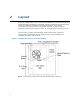
2.3.1 Thin Mini-ITX Back Panel I/O
The Thin Mini-ITX Back Panel I/O area is defined in Figure 4. The width of the back
panel I/O aperture and the location of the motherboard relative to the I/O aperture
are the same as Mini-ITX. This allows a Thin Mini-ITX board to be used in either a
Thin Mini-ITX chassis, or a Mini-ITX and larger compatible chassis when using an
appropriate I/O shield.
The thickness of the PCB and the topside I/O connectors shall fit within the .787”
(20mm) height shown in Figure 4. See section 2.4.2 for additional discussion.
Figure 4. Thin Mini-ITX Back Panel I/O
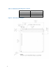
2.4 Height Constraints
2.4.1 Mini-ITX: Primary (Component) Side Height Constraints
One major advantages of the Mini-ITX form factor is its backward-compatibility with
the ATX specification. The Mini-ITX motherboard can be installed in any ATX chassis.
Figure 5 shows the required Mini-ITX maximum component height constraints for
the components on the PC board. For full compliance with Mini-ITX, and to prevent
interference with the chassis structure, power supply, or peripherals, the motherboard
components should not exceed the height limit in each zone defined. Similarly,
compliant power supplies, peripherals, and chassis features should not extend into the
motherboard component area.