
Data Sheet

Compute Module 3+ Datasheet
Copyright Raspberry Pi (Trading) Ltd. 2019
When initially powered on, or after the RUN pin has been held low and then released, the BCM2837
will try to access the primary SD/eMMC interface. It will then look for a file called bootcode.bin on the
primary partition (which must be FAT) to start booting the system. If it cannot access the SD/eMMC
device or the boot code cannot be found, it will fall back to waiting for boot code to be written to it over
USB; in other words, its USB port is in slave mode waiting to accept boot code from a suitable host.
A USB boot tool is available on Github which allows a host PC running Linux to write the BCM2837
boot code over USB to the module. That boot code then runs and provides access to the SD/eMMC as a
USB mass storage device, which can then be read and written using the host PC. Note that a Raspberry Pi
can be used as the host machine. For those using Windows a precompiled and packeged tool is available.
For more information see here.
The Compute Module has a pin called EMMC DISABLE N which when shorted to GND will disable
the SD/eMMC interface (by physically disconnecting the SD CMD pin), forcing BCM2837 to boot from
USB. Note that when the eMMC is disabled in this way, it takes a couple of seconds from powering up
for the processor to stop attempting to talk to the SD/eMMC device and fall back to booting from USB.
Note that once booted over USB, BCM2837 needs to re-enable the SD/eMMC device (by releasing
EMMC DISABLE N) to allow access to it as mass storage. It expects to be able to do this by driving
the EMMC EN N 1V8 pin LOW, which at boot is initially an input with a pull up to 1V8. If an end user
wishes to add the ability to access the SD/eMMC over USB in their product, similar circuitry to that
used on the Compute Module IO Board to enable/disable the USB boot and SD/eMMC must be used;
that is, EMMC DISABLE N pulled low via MOSFET(s) and released again by MOSFET, with the gate
controlled by EMMC EN N 1V8. Ensure you use MOSFETs suitable for switching at 1.8V (i.e. use
a device with gate threshold voltage, Vt, suitable for 1.8V switching).
9 Peripherals
9.1 GPIO
BCM2837 has in total 54 GPIO lines in 3 separate voltage banks. All GPIO pins have at least two
alternative functions within the SoC. When not used for the alternate peripheral function, each GPIO
pin may be set as an input (optionally as an interrupt) or an output. The alternate functions are usually
peripheral I/Os, and most peripherals appear twice to allow flexibility on the choice of I/O voltage.
GPIO bank2 is used on the module to connect to the eMMC device and for an on-board I2C bus (to talk
to the core SMPS and control the special function pins). On CM3+ Lite most of bank2 is exposed to
allow a user to connect their choice of SD card or eMMC device (if required).
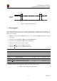
Bank0 and 1 GPIOs are available for general use. GPIO0 to GPIO27 are bank0 and GPIO28-45 make
up bank1. GPIO0-27 VDD is the power supply for bank0 and GPIO28-45 VDD is the power supply for
bank1. SDX VDD is the supply for bank2 on CM3+ Lite. These supplies can be in the range 1.8V-3.3V
(see Table 7) and are not optional; each bank must be powered, even when none of the GPIOs for that
bank are used.
Note that the HDMI HPD N 1V8 and EMMC EN N 1V8 pins are 1.8V IO and are used for special
functions (HDMI hot plug detect and boot control respectively). Please do not use these pins for
any other purpose, as the software for the module will always expect these pins to have these
special functions. If they are unused please leave them unconnected.
15 Release 2