
Technical data


Access to the Data of the AS-i Slaves
3-8
SIMATIC NET CP 243-2 AS-i Master
C79000-G8976-C142/02
3.2 Access to the Analog Data of the AS-i Slaves
(Slaves complying with Profile 7.3 or 7.4)
3.2.1 Addressing the Analog AS-i Slaves in the User Program
Requirements
Before you can access the I/O data of the AS-i slaves, the following requirements
must be met:
Deactivate the filtering of the analog inputs for the CP 243–2 in the system data
block of the S7–200 CPU.
Set the “PLC_RUN” bit (bit 7) in the digital control byte to ’1’ at the beginning of
the cyclic program.
Access to the I/O data of the slaves is then only allowed when the “CP_Ready”
bit (bit 1) in the digital status byte is set to ’1’.
The following explanations do not apply to analog slaves complying with profile 7.1
or 7.2. Analog value transfer for these slaves is not supported by the CP 243-2.
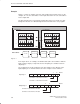
Access to the Analog Values
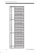
The CP 243-2 assigns four words in the input area and four words in the output
area for each AS-i slave. The PLC can write these values (analog outputs) or read
these values (analog inputs).
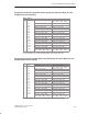
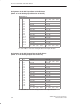
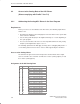
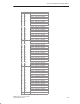
Assignment of the AS-i Analog Data
Bank Byte no. Meaning
32 0 Slave 1, channel 1, high byte
32 1 Slave 1, channel 1, low byte
32 2 Slave 1, channel 2, high byte
32 3 Slave 1, channel 2, low byte
32 4 Slave 1, channel 3, high byte
32 5 Slave 1, channel 3, low byte
32 6 Slave 1, channel 4, high byte
32 7 Slave 1, channel 4, low byte
32 8 Slave 2, channel 1, high byte
32 9 Slave 2, channel 1, low byte
32 10 Slave 2, channel 2, high byte
32 11 Slave 2, channel 2, low byte
32 12 Slave 2, channel 3, high byte
32 13 Slave 2, channel 3, low byte
32 14 Slave 2, channel 4, high byte
32 15 Slave 2, channel 4, low byte