
User Guide User Manual


Alto-6ch Hardware User Guide – V1.0 4
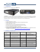
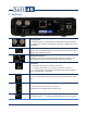
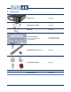
5 Back Panel
2 analog outputs
The unit allows up to 2 output channels trough the Lemo type connectors.
Each output owns a small 4-state LED (off, red, green, orange) that can use
the software.
Mini USB connector
Usually, a PC is connected to the Alto-6ch unit trough this connector. Most
software uses the USB connector.
RJ45 Ethernet connector
Alternatively, one could control the Alto-6ch trough this connector. The
Ethernet feature requires the software to be designed accordingly.
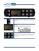
Board status
Red: only half a second at the power-up of the unit
Orange: shortly after power-up, it
indicates that the DSP is functional
Green: once the unit is connected to a PC trough a USB cable, it indicates
that the communication is functional.
External power connector
The unit can be powered externally, usually with the provided 15 V power
pack.
Power Switch
This switch turns the board on (“1”) or off (“0”).
The battery can be charged while the switch is off.
Charge Status
This indicator lights green to indicate that the internal battery is charging.