
Data Sheet


DS18B20
12 of 27
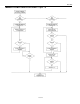
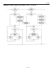
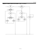
Example of a ROM Search
The ROM search process is the repetition of a simple three-step routine: read a bit, read the complement
of the bit, then write the desired value of that bit. The bus master performs this simple, three-step routine
on each bit of the ROM. After one complete pass, the bus master knows the contents of the ROM in one
device. The remaining number of devices and their ROM codes may be identified by additional passes.
The following example of the ROM search process assumes four different devices are connected to the
same 1-Wire bus. The ROM data of the four devices is as shown:
ROM1 00110101...
ROM2 10101010...
ROM3 11110101...
ROM4 00010001...
The search process is as follows:
1. The bus master begins the initialization sequence by issuing a reset pulse. The slave devices respond
by issuing simultaneous presence pulses.
2. The bus master will then issue the Search ROM command on the 1-Wire bus.
3. The bus master reads a bit from the 1-Wire bus. Each device will respond by placing the value of the
first bit of their respective ROM data onto the 1-Wire bus. ROM1 and ROM4 will place a 0 onto the
1-Wire bus, i.e., pull it low. ROM2 and ROM3 will place a 1 onto the 1-Wire bus by allowing the
line to stay high. The result is the logical AND of all devices on the line, therefore the bus master
sees a 0. The bus master reads another bit. Since the Search ROM data command is being executed,
all of the devices on the 1-Wire bus respond to this second read by placing the complement of the first
bit of their respective ROM data onto the 1-Wire bus. ROM1 and ROM4 will place a 1 onto the
1-Wire, allowing the line to stay high. ROM2 and ROM3 will place a 0 onto the 1-Wire, thus it will
be pulled low. The bus master again observes a 0 for the complement of the first ROM data bit. The
bus master has determined that there are some devices on the 1-Wire bus that have a 0 in the first
position and others that have a 1.
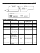
The data obtained from the two reads of the three-step routine have the following interpretations:
00 There are still devices attached which have conflicting bits in this position.
01 All devices still coupled have a 0-bit in this bit position.
10 All devices still coupled have a 1-bit in this bit position.
11 There are no devices attached to the 1-Wire bus.
4. The bus master writes a 0. This deselects ROM2 and ROM3 for the remainder of this search pass,
leaving only ROM1 and ROM4 connected to the 1-Wire bus.
5. The bus master performs two more reads and receives a 0-bit followed by a 1-bit. This indicates that
all devices still coupled to the bus have 0s as their second ROM data bit.
6. The bus master then writes a 0 to keep both ROM1 and ROM4 coupled.
7. The bus master executes two reads and receives two 0-bits. This indicates that both 1-bits and 0-bits
exist as the 3rd bit of the ROM data of the attached devices.