
User's Manual


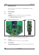


Table Of Contents

Running the STM32W-RFCKIT RF control kit UM1050
6/8 Doc ID 18433 Rev 1
3.1.2 Basic RF communication using the talk demonstration application
Once the talk application has been loaded on the kit's board, different RF communication
scenarios can be targeted as described in the table below.
Note: 1 When pressing a button on the application board, LED D1 is turned on, indicating a packet
is going to be sent.
2 When pressing a button on the application board, if something is wrong with the current RF
communication (packet transmission failed or no acknowledgment received from the USB
dongle), the application board LEDs D1 and D3 start blinking for few seconds.
For setting a “chat communication”, it is requested to setup a serial communication channel
on both kit's boards by following the steps described in Section 2.3.3: Setting up the
application serial communication channel.
Once the serial communication channels of the kit's boards are correctly configured, the two
talk demonstration applications can communicate by typing the “chat text” on the
corresponding HyperTerminal.
The above example application shows how an RS-232 cable connection between two
devices can be replaced with a wireless system using STM32W108xx microcontrollers.
Table 1. Supported talk RF control scenarios through application board buttons
Application board USB dongle
Press button S1 LED D1 toggles
Press button S2 LED D3 toggles
Press button S3 LED D1, D3 both toggle
Press button S4 LED D1 blinks for few seconds
Press button S5 LED D3 blinks for few seconds