
Based Data Acquisition and Control System User's Manual

Chapter 5
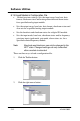
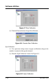
•
Address: Represents the address of the module. The Range is from
0 to 255.
•
Baudrate: Represents the baud rate.
•
Checksum: Represents the checksum status, i.e., Disabled/
Enabled.
•
Firmware Ver: Represents the version of firmware.
•
Input range: Represents the input range of modules. You can refer
to Chapter 4.
•
Data format: Represents the data format (e.g. engineering format).
You can refer to Chapter 4.
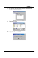
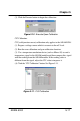
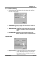
5.1.10 Module Calibration
Calibration is to adjust the accuracy of ADAM module. There are
several modes for module’s calibration: Zero calibration and span
calibration. Only analog input and output modules can be calibrated.
Note: The calibrating function supports ADAM-5013/5017/5017H/
5018/5024.
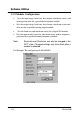
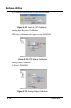
Zero Calibration:
(1). Apply power to the module and let it warm up for about 30 minutes.
(2). Make sure that the module is correctly installed and is properly
configured for the input range you want to calibrate.
(3). Use a precision voltage source to apply a calibration voltage to the
modules’ terminals of the specific channel.
(4). Click the “Zero Calibration” button. See Figure 5-7
5-16 ADAM-5000