
Troubleshooting guide


9. [NOAO slit in mask] Center the target.
• The Decker wheel should already be in the mos position.
• Move the slit mask into the beam using config.rel.mv.mos.wheel.pl [Move MOS Wheel]
• Take an image; one should see the target in the alignment box in the mask
• Use relative.offset.kpno.pl or ask the telescope operator move the telescope to center the star in
the alignment box. This may take several iterations.
• Offset the telescope 60 arcsec in the direction of the rotator position angle. This will center the
star in the lower of the two slits. The lower slit is preferred because the upper right quadrant of the
array has higher read noise which may adversely affect the S/N of the spectrum.
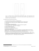
10. [MOS mask] Center the alignment stars in their boxes
• Move the MOS mask into position and take another image. One should see the alignment star in the
largest box.
• Move the telescope to center the alignment star in the largest box. At this point, one should see the
alignment stars in the other boxes as well.
• If one alignment star is centered in its box, but the others are not, it may be necessary to rotate the
MOS wheel slightly using tweak.mos.pl. One should rotate in very small increments (0.1 degrees or so),
since the alignment should be close and one wants to keep the alignment stars in their boxes. A rotation
of 0.1 degrees is about 3 pixels relative motion over the length of the mask. Positive tweak values move
the mask couterclockwise on the display.
• Move the telescope to center the alignment star in the largest box and check the positions of the other
alignment stars. This should allow one to estimate the additional MOS wheel rotation, if any, required to
center all the alignment stars and put the targets within their slitlets.
D. MOS Plate Alignment (using xbox)
An alternative mask alignment procedure is done using a modified version of the IRAF task xbox, from the
ucsclris package. A mask should have 2 – 4 boxes (in addition to the slitlets) which correspond to bright
alignment targets. Given an image of the mask, and two files, one containing the approximate locations of the
boxes, and one containing the corresponding star locations, xbox will allow you to quickly determine the
translational and rotational shifts required to center these targets in their corresponding boxes.
Xbox will output translational offsets, in arcseconds, that should correspond to (δRA, δDec), and a rotational
offset in degrees. The 4-m instrument rotator is not very precise and cannot be adjusted away from the zenith,
so it may not be used for the rotational offset. The MOS wheel must be rotated instead. After every translation
and/or rotation a new image must be taken, and new box and star files generated.
There are 10 important parameters that should be double checked against the complete listing of the xbox
parameters given in Appendix 3. There are three parameters that you may need to change:
1. xsz and ysz
• The widths in pixels of the alignment boxes in the x and y directions.
• All of the boxes are of the same size.
• We typically use alignment star boxes that are 24 – 30 pixels wide. It is very important that this
parameter be set to within a few pixels of the actual values.
2. rot_4m
• This is listed as the 4-m rotation offset, and it should directly correspond to the instrument position
angle. For example:
• If ROT_PA = 90: set rot_4m = -90.
Running xbox causes a graphics terminal to pop up. It steps through the boxes, in the order listed in the box file,
and presents a cross-cut profile for the x and y directions, along with a red graphics cursor. It will show the
FLAMINGOS@4-m, Ver. 2.39, 2013 April 23 Page 27 of 47