
DSP Core Reference Manual


Core Control Registers
SC140 DSP Core Reference Manual 3-7
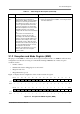
3.1.2 Exception and Mode Register (EMR)
The purpose of the EMR is to reflect and control exception situations in the core. EMR bits reflect memory
configuration as well as the servicing of non-maskable interrupts. EMR bits also reflect exception
conditions such as:
• DALU overflow
• EOnCE and software debugging access and control
• Illegal execution set
• Illegal instruction opcode
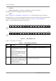
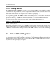
Figure 3-2 displays the bit configuration of the execution and mode register
.
Figure 3-2. Exception and Mode Register (EMR)
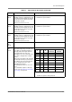
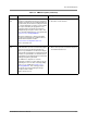
C
Bit 0
Carry Bit — Indicates whether a carry is
generated from the resulting most
significant bits (MSB) of the last addition
operation or a borrow generated in the
last subtraction operation. The carry or
borrow is generated from bit 39 of the
result. The carry bit is also affected by
DALU bit manipulation as well as rotate
and shift instructions. The carry bit
usually holds the value of the last shifted
bit.
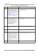
If more than one instruction in an
execution set affects the carry bit
(according to the instruction definition),
then the carry bit is updated by the last
instruction (in assembly source order)
that actually executes, while the other
instructions do not affect the carry bit. If
no carry-affecting instructions execute,
the carry bit is not affected.
This bit is cleared during core reset as
well as at the start of an exception
service routine.
0 = No carry or borrow generated
1 = Carry generated from last addition, or borrow generated
from last subtraction
BIT 31 30 29 28 27 26 25 24 23 22 21 20 19 18 17 16
GP6 GP5 GP4 GP3 GP2 GP1 GP0 BEM
TYPE r r r r r r r r r r r r r r r r
RESET 0 0 0 0 0 0 0 0 IO IO IO IO IO IO IO IO
BIT 15 14 13 12 11 10 9 8 7 6 5 4 3 2 1 BIT 0
NMID DOVF ILST ILIN
TYPE r r r r r r r r r r r r rw rw rw rw
RESET 0 0 0 0 0 0 0 0 0 0 0 0 0 0 0 0
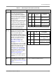
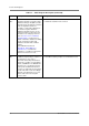
Table 3-1. Status Register Description (Continued)
Name Description Settings