
DSP Core Reference Manual


4-26 SC140 DSP Core Reference Manual
EOnCE Module Internal Architecture
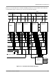
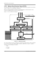
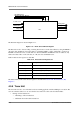
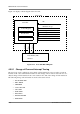
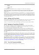
The ES block diagram is shown in Figure 4-13.
Figure 4-13. Event Selector Block Diagram
The ES can be used to detect reading or writing data from/to a certain data address by using the EDCD to
detect the data, an EDCA to detect the address (on XABA, XABB, or both), and the ES to generate an
EOnCE event if both events occur. In this case, when both EDCA and EDCD events are selected, only
address and data values on the same bus (A or B) can cause an EOnCE event.
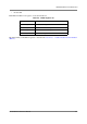
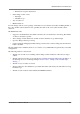
Table 4-10 shows the register set of the ES.
The functionality of the event selector registers is described in Section 4.10, “Event Selector (ES)
Registers.”
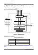
4.5.5 Trace Unit
The trace unit is used to store information about a running application without halting its execution. The
user can select the addresses to be stored in the trace unit from a wide selection that includes:
• Change-of-flow instructions
— All Change-of-flow instructions
— Call/return from subroutine instructions
Table 4-10. Event Selector Register Set
Register Name Description
ESEL_CTRL ES control register
ESEL_DM ES mask debug state register
ESEL_DI ES mask debug exception register
ESEL_ETB ES mask enable trace register
ESEL_DTB ES mask disable trace register
ES
Debug State
Debug Exception
Enable Trace
Disable Trace
Event0..Event5
EventD
Count event
DEBUGEV
EE[4:0]
External Event6, Event7