
User's Manual


A-5
INSTRUCTION SET REFERENCE
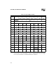
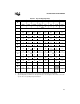
Table A-3 shows the effect of the PSW flags or a specified condition on conditional jump instruc-
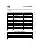
tions. Table A-4 defines the symbols used in Table A-6 to show the effect of each instruction on
the PSW flags.
.
Table A-3. Effect of PSW Flags or Specified Conditions on Conditional Jump Instructions
Instruction Jumps to Destination if Continues if
DJNZ decremented byte ≠ 0 decremented byte = 0
DJNZW decremented word ≠ 0 decremented word = 0
JBC specified register bit = 0 specified register bit = 1
JBS specified register bit = 1 specified register bit = 0
JNC C = 0 C = 1
JNH C = 0 OR Z = 1 C = 1 AND Z = 0
JC C = 1 C = 0
JH C = 1 AND Z = 0 C = 0 OR Z = 1
JGE N = 0 N = 1
JGT N = 0 AND Z = 0 N = 1 OR Z = 1
JLT N = 1 N = 0
JLE N = 1 OR Z = 1 N = 0 AND Z = 0
JNST ST = 0 ST = 1
JST ST = 1 ST = 0
JNV V = 0 V = 1
JV V = 1 V = 0
JNVT VT = 0 VT = 1 (clears VT)
JVT VT = 1 (clears VT) VT = 0
JNE Z = 0 Z = 1
JE Z = 1 Z = 0
Table A-4. PSW Flag Setting Symbols
Symbol Description
✓ The instruction sets or clears the flag, as appropriate.
— The instruction does not modify the flag.
↓ The instruction may clear the flag, if it is appropriate, but cannot set it.
↑ The instruction may set the flag, if it is appropriate, but cannot clear it.
1 The instruction sets the flag.
0 The instruction clears the flag.
? The instruction leaves the flag in an indeterminate state.