
Microprocessor User's Manual

User’s Manual 205
If the user for some reason wants to depart from the suggested protocols and poll a register
while waiting for the other side to write something to the register, the user should be aware
that all the bits might not change at the exact same time when the result changes, and a
transitional value could be read from the register where some bits have changed to the new
value and others have not. To avoid being confused by a transitional value, the user can
read the register twice and make sure both values are the same before accepting the value,
or the user can test only one bit for a change. The transitional value can only exist for one
read of the register, and each bit will have its old value change to the new value at some
point without wavering back and forth. The existence of a transitional value could be very
rare and has the potential to create a bug that happens often enough to be serious, but so
infrequently as to be difficult to diagnose. Thus, the user is cautioned to avoid this situa-
tion.
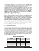
Table 13-2 describes the slave port control register.
The functionality of the bits is as follows:
Bit 7—If set to "0," the cold-boot feature will be enabled. Normally this bit is set to a "1"
after the cold boot is complete. The cold boot for the slave port is enabled automatically if
(SMODE1, SMODE0) lines are set to (0,1) after the reset ends. This features disables the
normal operation of the processor and causes commands to be accepted via the slave port
register SPD0R. These commands cause data to be stored in memory or I/O space. When
the master that is managing the cold boot has finished setting up memory and I/O space,
the (SMODE1, SMODE0) pins are changed to code (0,0), which causes execution to start
at address zero. Typically this will start execution of a secondary boot program. At some
point, bit 7 will be set to a "1" so that the SMODEx pins can be used as normal input pins.
Bits 6,5—May be used to read the input pins SMODE, SMODE0.
Bits 3,2—A “10” written to bits 3,2 enables the slave port disabling Parallel Port A and vari-
ous other port lines. Bits 3,2 are automatically set to a "10" if a cold boot is done via the
slave port. If bit 3 is "0," then bit 2 controls whether Parallel Port A is an input (bit 2 = 0)
or an output (bit 2 = 1). A “11” written to bits 3,2 enables the Auxilliary I/O bus.
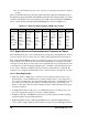
Table 13-2. Slave Port Control Register (SPCR) (adr = 0x024)
Bit 7
(Write Only)
Bits 6,5
(Read Only)
Bit 4
Bit 3,2
(Write Only)
Bits 1,0
(Write Only)
0—obey SMODE
pins
1—ignore SMODE
pins
Reads SMODE
pins
smode1,smode0
x
00—disable slave port, port A
is a byte wide input port
01—disable slave port, port A
is a byte wide output port
10—enable the slave port
11—Enable the auxilliary I/O
bus. Parallel Port A is used
for the data bus and Parallel
Port B[7:2] is used for the
address bus.
00—no slave
interrupt
pp—enable slave
port interrupt
01 priority 1
10 priority 2
11 priority 3