
User guide
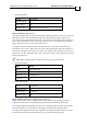
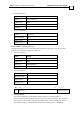

The following table lists the values used to define the digital input transitions:
DIN Mask Value DIN Logic Level for Activating an Event
0 No event occurs.
1 Switched from low to high (↑).
2 Switched from high to low (↓).
3 Switched (↑ or ↓).
When a DIN event occurs, the mapped TPDO is transmitted. The DIN mask value is
determined according to a 2-bit field of the digital input.
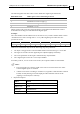
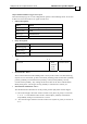
Example:
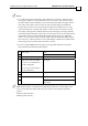
The value 0x00A1 sets the DIN4 event to “Event on every switch” and the DIN1 event to
“Switch from low active to high active.” every other digital input switch does not
produce an event:
DIN6 DIN5 DIN4 DIN3 DIN2 DIN1
0 0 0 0 1 1 0 0 0 0 0 1
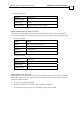
TPDOs are transmitted only when the following steps are performed:
1. An object is mapped to the relevant TPDO and the transmission type is set to 254.
2. The logic level of the relevant digital input is adjusted (IL[N] command).
3. The event parameter of the input is determined by object 0x2F23.
4. The “digital input event” bit is set in object 0x20F0.
From this point on, as soon as the event occurs, the requested TPDO is transmitted.
Notes:
If several inputs are selected, a DIN event will occur when at least one of the
selected digital inputs is switched.
A DIN event occurs according to switch level, regardless of the function selected
for that switch (details given in the IL[N] and IP command sections of the
SimplIQ Command Reference Manual).
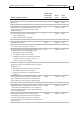
Object description:
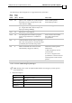
Index 2F23h
Name Digital input TPDO event parameters
Object code VAR
Data type UNSIGNED16
Category
CANopen DS 301 Implementation Guide Manufacturer-specific Objects
MAN-CAN301IG (Ver. 2.1)
13-30