
DSP Core Reference Manual


EOnCE Controller Registers
SC140 DSP Core Reference Manual 4-45
4.7.6.1.4 Status Bit of the ETRSMT Register
The EE4 signal can be programmed to serve as an indication of data availability in the ETRSMT register.
This capability provides interrupt driven transfers to the host debugger. If the EE4 signal is programmed in
this way, each time the core performs the transfer (and writes to the ETRSMT register), the EE4 signal is
asserted and the host is interrupted. The EE4 signal is negated when the host has finished reading the
ETRSMT register through the JTAG.
4.7.6.2 EE Signals as Inputs
EE signals can be programmed to enable event detection channels or to generate one of the EOnCE events.
After reset, the EE signals are set as inputs. When programmed as an input, an EE signal must be driven
with zero or one. EE assertion can be programmed to perform several functions. For example, EE2 can
enable both EDCA2 and the event counter as well as generate any of the EOnCE events at the same time.
4.7.6.2.1 Using EE Signals to Enable Event Detection Channels
Each EE signal can be programmed to enable the corresponding address detection channel or the data
detection channel. The user can configure EE0 to enable EDCA0, EE1 to enable EDCA1, EE2 to enable
EDCA2, and so on. EED can also be configured to enable EDCD. For a description of how address event
detection channels can be configured to be enabled upon an appropriate EE assertion, see Section 4.9.1.1,
“EDCA Control Registers (EDCAi_CTRL),” and Section 4.9.2.1, “EDCD Control Register
(EDCD_CTRL).”
4.7.6.2.2 Using EE Signals to Cause EOnCE Events
If programmed by the user, EE signal assertion can cause any of the following EOnCE events:
• Place the core in debug state.
• Cause a debug exception.
• Enable trace buffer.
• Disable trace buffer.
4.7.6.2.3 Using EE Signals to Enter Debug State
The EE0 signal by default can cause the core to enter debug state right after core reset. It can also cause the
core to leave a wait or stop state and enter debug state.
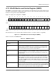
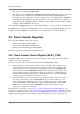
4.7.6.3 EE Signals Control Register (EE_CTRL)
This 16-bit register defines the behavior of the EE signals.
Figure 4-18 displays the bit configuration of the EE signals control register. Shaded bits are reserved and
should be initialized with zeros for future software compatibility.
Figure 4-18. EE Signals Control Register (EE_CTRL)
BIT 15 14 13 12 11 10 9 8 7 6 5 4 3 2 1 BIT 0
EEDDEF EE5DEF EE4DEF EE3DEF EE2DEF EE1DEF EE0DEF
TYPE rw rw rw rw rw rw rw rw rw rw rw rw rw rw rw rw
RESET 1 1 1 1 1 1 1 1 1 1 1 1 1 1 1 1