
8-Bit Microcontroller with OTP ROM Specification Sheet


EM78P447N
8-Bit Microcontroller with OTP ROM
Product Specification (V1.1) 03.30.2005
• 11
(This specification is subject to change without further notice)
4.1.8 R3F (Interrupt Status Register)
Bit 7 Bit 6 Bit 5 Bit 4 Bit 3 Bit 2 Bit 1 Bit 0
- - - - EXIF - - TCIF
Bit 3 (EXIF) External interrupt flag. Set by falling edge on /INT pin, flag cleared by
software
Bit 0 (TCIF) the TCC overflow interrupt flag. Set as TCC overflows; flag cleared by
software.
Bits 1, 2, 4~7 are not used and read are as “0”.
"1" means interrupt request, "0" means non-interrupt.
R3F can be cleared by instruction, but cannot be set by instruction.
IOCF is the interrupt mask register.
Note that reading R3F will obtain the result of the R3F "logic AND" and IOCF.
4.2 Special Purpose Registers
4.2.1 A (Accumulator)
Internal data transfer, or instruction operand holding.
It cannot be addressed.
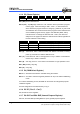
4.2.2 CONT (Control Register)
7 6 5 4 3 2 1 0
/PHEN /INT TS TE PAB PSR2 PSR1 PSR0
Bit 7 (/PHEN) Control bit used to enable the pull-high of P60~P67, P74 and P75 pins
0: Enable internal pull-high.
1: Disable internal pull-high.
CONT register is both readable and writable.
Bit 6 (/INT) Interrupt enable flag
0: masked by DISI or hardware interrupt
1: enabled by ENI/RETI instructions
Bit 5 (TS) TCC signal source
0: internal instruction cycle clock
1: transition on TCC pin