
Datasheet


LT3435
13
3435fa
To calculate actual peak switch current in continuous
mode with a given set of conditions, use:
II
VVV
LfV
SW PK OUT
OUT IN OUT
IN
()
–
=+
()
()()( )
2
If a small inductor is chosen which results in discontinous
mode operation over the entire load range, the maximum
load current is equal to:
I
IfLV
VVV
OUT MAX
PK IN
OUT IN OUT
()
–
=
()( )( )
()( )
2
2
2
CHOOSING THE INDUCTOR
For most applications the output inductor will fall in the
range of 5µH to 33µH. Lower values are chosen to reduce
physical size of the inductor. Higher values allow more
output current because they reduce peak current seen by
the LT3435 switch, which has a 3A limit. Higher values
also reduce output ripple voltage and reduce core loss.
When choosing an inductor you might have to consider
maximum load current, core and copper losses, allow-
able component height, output voltage ripple, EMI, fault
current in the inductor, saturation and of course cost.
The following procedure is suggested as a way of han-
dling these somewhat complicated and conflicting
requirements.
1. Choose a value in microhenries such that
the maximum
load current plus half of the inductor ripple current is
less than the minimum peak switch current (I
PK
).
Choosing a small inductor with lighter loads may result
in discontinuous mode of operation, but the LT3435 is
designed to work well in either mode.
Assume that the average inductor current is equal to
load current and decide whether or not the inductor
must withstand continuous fault conditions. If maxi-
mum load current is 1A, for instance, a 1A inductor may
not survive a continuous 4A overload condition.
For applications with a duty cycle above 50%, the
inductor value should be chosen to obtain an inductor
ripple current of less than 40% of the peak switch
current.
2. Calculate peak inductor current at full load current to
ensure that the inductor will not saturate. Peak current
can be significantly higher than output current, especially
with smaller inductors and lighter loads, so don’t omit
this step. Powdered iron cores are forgiving because they
saturate softly, whereas ferrite cores saturate abruptly.
Other core materials fall somewhere in between. The
following formula assumes continuous mode of opera-
tion, but it errs only slightly on the high side for discon-
tinuous mode, so it can be used for all conditions.
II
VVV
fLV
PEAK OUT
OUT IN OUT
IN
=+
()
()( )( )
–
2
V
IN
= maximum input voltage
f = switching frequency, 500kHz
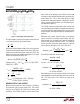
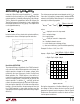
Table 3. Inductor Selection Criteria
VENDOR/ VALUE I
DC(MAX)
DCR HEIGHT
PART NO. (
µ
H) (Amps) (Ohms) (mm)
Sumida
CDRH104R-4R7 4.7 6 0.013 4
CDRH104R-100 10 4.4 0.035 4
CDRH104R-150 15 3.6 0.050 4
CDRH104R-220 22 2.9 0.073 4
CDRH104R-330 33 2.3 0.093 4
CDRH124-4R7 4.7 5.7 0.015 4.5
CDRH124-100 10 4.5 0.026 4.5
CDRH124-220 22 2.9 0.066 4.5
CDRH124R-330 33 2.7 0.097 4.5
CDRH127-330 33 3.0 0.065 8
CEI122-220 22 2.3 0.085 34
Coiltronics
UP3B-4R7 4.7 6.5 0.0083 6.8
UP3B-4R7 10 4.3 0.026 6.8
UP3B-330 33 3 0.069 6.8
APPLICATIO S I FOR ATIO
WUUU