
Instruction Manual


Logic Functions - Book 1
ANALOG INPUT MODULE BLOCKS (VCIM, TIM, RIM, WRIM)
5-42
18
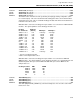
Extended Error Code
(EXTERR) ......................................................................................– WR
The extended error code is a bitmapped two byte (16 bit) error code from the module that is
presented as a count value. The count value must be converted to binary to decode the
following bit mapped error pattern:
Bit Extended Errors (Lower Byte) Bit Status Errors (Upper Byte)
0 UART Timeout 8 VRAM (0=Low, 1=High)
1 Checksum Error 9 Calibration Data (0=Low, 1=High)
2 REG__ Range Error 10 Line Frequency Status (0=60Hz, 1=50Hz)
3 EPROM Error 11 Calculation Status (0=No Calc., 1=Calc.)
4 Calibration Error 12 *Module Error Status (0=No Error, =Error)
5 UART Error 13 Done Status (0=Not Complete, 1=Comp.)
6 A/D Converter Error 14 Under Range (0=Not Under, 1=Under)
7 Reserved 15 Over Range (0= Not Over, 1=Over)
* Lower bits 0-7 define module error status when = 1.
VCIM 19
Mode
(MODE)..................................................................................................................... CWR
TIM 19
Mode
(MODE)..................................................................................................................... CWR
RIM 20
Mode
(MODE)..................................................................................................................... CWR
WRIM 20
Mode
(MODE)..................................................................................................................... CWR
The mode of the block is determined by configuring and/or writing this attribute. Switching
mode is a reportable event. The manual mode causes the result quality to be good. If a cold
junction input module were to go bad, switching to manual would prevent bad data quality
from appearing on all thermocouple inputs that use the correction.
MAN 0 The block input is the previous result or the last written result.
AUTO 1 The block input is processed using the input module data.
RIM 19
Input Type
(INTYPE) .........................................................................................................C – R
WRIM 19
Input Type
(INTYPE) .........................................................................................................C – R
For RIM and WRIM block types only. The input type parameter further identifies the
resistance input module block as applying to one of the following.
RTD 0 Standard RTD linearization used.
NON-RTD 1 Resistance input or RTD not supported by software linearization
(piecewise table required).
VCIM 20
Input Type
(INTYPE) .........................................................................................................C – R
For VCIM block types only. The input type parameter further identifies the voltage/current
input module block as applying to one of the following.
VOLTS 0 Input module is a 2001A Voltage Input Module. The input
range is set to ±10V dc by this selection.
MILLIVOLTS 1 Input module is a 2001A Voltage Input Module. The input
range is set to ±100mV dc by this selection. If the input is
from a temperature transmitter, configure thermocouple to
identify type.
PASSIVE CURRENT 2 Input module is a 2002A Current Input Module.
ACTIVE CURRENT 3 Input module is a 2012A Current Input Module with 2-wire
transmitter power.