
User's Guide

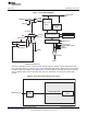


CNTHI
Internal
clock
Externalclock
viaTINPL
32-bitprescalecounter Prescaleperiod
Equalitycomparator
PRDHI
Inputclock
32-bitprescaler
(TIMHI)
32-bittimer
(TIMLO)
CP_LO
PWID_LO(CP_LO=0)
Pulsegenerator
CLKSRC
Gatedinternalclock
Timerinterrupt(TINTLO)toCPU
Timerevent(TEVTLO)toEDMA controller
INVOUTP_LO
TSTATbitinTCR
OutputviaTOUTL
CNTLO
32-bittimercounter
Timerperiod
Equalitycomparator
PRDLO
www.ti.com
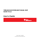
Timer Modes
2.2.1 Chained Mode
In the chained mode, shown in Figure 4, one 32-bit timer (TIMHI) is used as a 32-bit prescaler to a second
timer (TIMLO).
The 32-bit prescaler (TIMHI) uses the counter register (CNTHI) and the period register (PRDHI) to form a
32-bit prescale counter register and a 32-bit prescale period register, respectively. When the timer is
enabled, the prescale counter starts incrementing by 1 at every timer input clock cycle. One cycle after the
prescale counter matches the prescale period, a clock signal is generated and the prescale counter
register is reset to 0 (see the example in Figure 5).
The other 32-bit timer (TIMLO) uses the counter register (CNTLO) and the period register (PRDLO) to
form a 32-bit timer counter register and a 32-bit timer period register, respectively. This timer is clocked by
the output clock from the prescaler (see the example in Figure 5). The timer counter increments by 1 at
every prescaler output clock cycle. When the timer counter matches the timer period, a maskable timer
interrupt (TINTLO), a timer EDMA event (TEVTLO), and an output signal are generated. When in pulse
mode (CP_LO = 0), the timer output (TOUTL) asserts a pulse that is 1, 2, 3, or 4 timer clock cycles wide,
depending on the setting of the pulse width (PWID) bits in the timer control register (TCR). When the timer
is configured in continuous mode, the timer counter is reset to 0 on the cycle after the timer counter
reaches the timer period. The timer can be stopped, restarted, reset, or disabled using the bits of the timer
control register. The timer control register (TCR) does not control the TIMHI in this mode.
Figure 4. Dual 32-Bit Timers Chained Mode Block Diagram
9
SPRU818B–December 2005–Revised September 2010 C6472/TCI648x 64-Bit Timer
Submit Documentation Feedback
Copyright © 2005–2010, Texas Instruments Incorporated