
Installation manual

12
6.0 OPERATIONAL DISPLAY AND PROGRAMMING
6.1 Static Weld Display Screens
The WC 1 controller provides a 2-line 16-character display and four control switches that allow the
user to program the weld variables and to select the various weld schedules. When not altering
parameters the display will indicate current status of the controller. The first line of the display will
show the product type message. The Second line will show the current set point value for the
analog outputs that are enabled. The values displayed are the final values for each weld cycle
event. The values are not varied during the ramp or pulse event but are set to the end or peak
values. The actual values displayed are the result of the control mode and options installed. The
following are the various Weld active Display screens that will be displayed, during a weld cycle, on
the second line of the display.
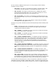
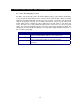
DISPLAY MESSAGE DESCRIPTION
AMP=### This screen will be displayed for PAW and GTAW mode when the wire drive
option is not installed. (Where: ## # is the current set point value)
AMP=### WFS=### This screen will be displayed for PAW and GTAW mode when the wire drive
option is installed. (Where: ### is The current set point value)
VOL=##.# WFS=###
This screen will be displayed for GMAW mode. (Where: ### is The current set
point value)
Table 1 - Static Screen Display Message