
Technical data
Setup
8 312185S
Setup
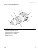
Fluid and Air Connections
9/16 Straight Thread O-Ring Boss Fluid
Inlets
There is one fluid inlet on the A-side and one fluid inlet
on the B-side. The fluid inlets are located on the side of
the valve and swivel to permit various mounting and
hose configurations.
1/8 npt(f) Air Inlets
The machine mount valves and the electric switch
hand-held valves have an on port (I) and off port (O),
which are operated by a remote 4-way air control valve.
Use one of the two air inlets located on the bottom and
on the back of the valve.
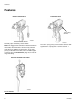
The air switch hand-held valves have a single air inlet
with an internal 4-way spool which operates the air pis-
ton.
See Accessories on page 19, to order air control valves
and tubing.
Inlet Check Valves
Inlet check valves are recommended on the fluid inlets
where viscosity allows. An inlet check valve prevents
back-flow or crossover when the mixer is plugged or one
fluid is much lower viscosity than the other. When
required, a high crack pressure check valve is installed
to maintain back-pressure on low viscosity fluids.
See Accessories on page 19 for a list of check valves.
Balancing the System
A proportioner is used to feed the two-component dis-
pense valve. The system must be pressure balanced to
avoid “lead-lag” ratio errors when starting and stopping
the flow.
Balancing is done by hose sizing or inlet check restric-
tion. A properly balanced system has near equal
back-pressure on the gauges when flowing without a
mixer installed.
Selecting Hoses
Hoses between your proportioner and the MD2 valve
should be selected carefully. Many factors effect hose
selection.
1. Fluid Compatibility: Fluid must not degrade the
core material or end fittings of the hose. Nylon or
PTFE cores are commonly used for chemical com-
patibility. If your fluid is moisture sensitive you
should use PTFE or Moisture-Lok hoses.
2. Pressure Rating: Be sure hoses have a working
pressure rating above the pressure capability of the
system.
3. Compressibility: Hoses, especially nylon paint
hoses, expand with an increase in pressure. A pres-
sure change in the system may cause a volume
change, which can appear as a ratio error with wide
mix ratios. Compressible hoses absorb pressure
spikes which is helpful to the operator during an
application, such as trying to lay a bead.
4. Internal Diameter: Small I.D.'s create higher back
pressures, lower flows, and small retained volume.
Typically hose I.D.'s are selected for:
a. System Pressure Balance. “A” pressure drop
vs. “B” pressure drop.
b. Volume Balance. A:B volume ratio vs. Hose
retained volume.
c. Flexibility and weight for operator or robot.
d. Overall Pressure Drop. Pressure drop should be
minimum possible within the above guidelines.
5. Length: Hoses normally are kept as short as practi-
cal to minimize pressure drop and compressible vol-
ume. 10 ft (3.1 m) is recommended for reciprocating
pump systems.