
Reference Manual

16-Axis MACRO CPU Software Reference Manual
22 16-Axis MACRO Station MI-Variable Reference
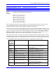
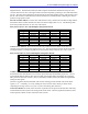
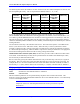
MI152 and MI153 are 48-bit values represented by 12 hexadecimal digits. These digits have the
following functions:
Digits Function and Setting
1 & 2 3
rd
I/O ASIC Latch Control (Maps into high bytes; ACC-9E, 10E, 11E, 12E
with E6x connecting rows 4 & 5)
=$C0 for latched inputs
=$00 for transparent inputs or ASIC not present
3 & 4 2
nd
I/O ASIC Latch Control (Maps into middle bytes ACC-9E, 10E, 11E, 12E
with E6x connecting rows 2 & 3)
=$C0 for latched inputs
=$00 for transparent inputs or ASIC not present
5 & 6 2
nd
I/O ASIC Latch Control (Maps into low bytes; ACC-9E, 10E, 11E, 12E
with E6x connecting rows 1 & 2)
=$C0 for latched inputs
=$00 for transparent inputs or ASIC not present
7 Number of bytes (1 to 6) on each ASIC (starting with lowest byte) to latch
8 (Reserved for future use; set to 0)
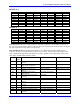
9 - 12 Base address of I/O Board
=$8800 (ACC-9E, 10E, 11E, 12E board w/ E1 ON, ACC-14E)
=$8840 (ACC-9E, 10E, 11E, 12E board w/ E2 ON, ACC-14E)
=$8880 (ACC-9E, 10E, 11E, 12E board w/ ON, ACC-14E)
=$88c0 (ACC-9E, 10E, 11E, 12E board w/ E4 ON, ACC-14E)
Examples:
MS0,MI153=$0000C0308840 ; Latches inputs on 1
st
ASIC, 1
st
3 bytes, of an
; ACC-14E board with base address $8840
MS{anynode},MI154 - MI160 (Reserved for Future Use)
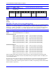
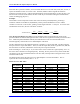
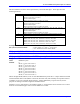
MS{anynode},MI161-MI168 MLDT Frequency Control
Range: $000000 - $FFFFFF
Units: PFMCLK cycles
Default: 0
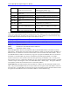
MI161 (1
st
motor node: Node 0)
MI162 (2
nd
motor node: Node 1)
MI163 (3
rd
motor node: Node 4)
MI164 (4
th
motor node: Node 5)
MI165 (5
th
motor node: Node 8)
MI166 (6
th
motor node: Node 9)
MI167 (7
th
motor node: Node 12)
MI168 (8
th
motor node: Node 13)
MI161 through MI168 (MI16x) on the 16-Axis MACRO Station permit the ‘C’ output channel associated
with the MACRO motor node (MI16x controls the xth motor node, which usually corresponds to Motor x
on PMAC) to put out a specified output frequency, starting immediately on power-on/reset, for the
purposes of creating an excitation signal for an MLDT sensor.
If MI16x is set to 0, this function is not enabled, and the ‘C’ output channel can be used for servo control
functions such as PFM stepper control or direct PWM servo control.