-
User's Guide U00086051201 Solvent Ink Color Inkjet Printer IP-6600 Océ CS 6060 Read this User's Guide to use the printer safely and properly. Keep this manual in a place where you can quickly access it at any time. Seiko I Infotech Inc.
-
IP-6600 Solvent Ink Color Inkjet Printer User's Guide Documents Number U00086051201 First Edition, December 2003 Second Edition, February 2004 Copyright © 2003, 2004 by Seiko I Infotech Inc. All rights reserved Seiko I Infotech Inc.
-
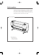
Introduction Thank you very much for purchasing the IP-6600 Color Inkjet Printer (simply called the printer below). This printer is a color inkjet printer that adopts solvent ink, supports 64 inch media width, and builts-in SCSI interface. This manual, the IP-6600 User's Guide, describes the features of the printer, names of components, information to be known before use, and basic operations, such as how to turn the power on and off and set media and ink.
-
-
Deliverables The printer components, including options, are installed on the main unit on delivery. Make sure that the following items are present. If any parts are missing or damaged, contact the shop where you purchased the product or the nearest service dealer. Basic components Printer main unit <1> • Built-in SCSI interface. • Including a winding unit.
-
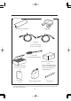
Accessories Roll paper(for installations) SCSI cable <1> <1> Power cord <2> • Power cord for printer • Power cord for heater + screw driver (for head up/down adjustment) Maintenance kit IP6-108 <1 set> • Cap cleaning liquid: 100 ml Ink kit 6 colors IP6-100 • Wiper cleaning liquid: 100 ml • Cleaning swab: 50 pieces (Y, M, C, Bk, Lc, Lm) <1> User's Guide <1 copy> *: • Syringe: 10 pieces Waste ink bottle IP6-109 <1> Paper tube 64" <1> Ink capacity of each ink cartridge for ink kit 6 colors IP6-10
-
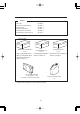
Options • Dryer 64 • Dryer 64 for North America (IP-260) : 1 (IP-263) : 1 • Roll Cover 64 • Exhaust Attachment (IP-261) : 1 (IP-262) : 1 • PS RIP (Photo Print 4 Dx) • PS RIP (Photo Print 4 Server) (IP-540) : 1 (IP-541) : 1 Consumables Maintenance Kit IP6-108 <1 set> • Cap cleaning liquid: 100 ml • Wiper cleaning liquid: 100 ml Cleaning Kit IP6-117 Storage Kit IP6-137 <1 set> <1 set> • Cleaning liquid cartridge: 6 • Maintenance liquid cartridge: 6 • Dummy cartridge: 6 • Dummy cartridge: 6 • Cleani
-
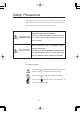
Safety Precautions The following symbols are used in this manual to ensure the proper use of the printer and to prevent the printer from being damaged. Follow the instructions marked with these symbols. WARNING Serious personal injury or death: Failure to follow the guidelines marked with this symbol could result in serious personal injury or death.
-
WARNING Use the power supply voltage specified on the nameplate. DO NOT plug several devices into one electrical outlet as this might result in fire or electric shock. Make sure the printer is well grounded. If not, a short circuit may cause fire or electrical shock. DO NOT disassemble or remodel the printer. DO NOT repair the printer by yourself. Doing so may cause fire, electric shock or other accidents. DO NOT damage, break, process, or heat the power cable. If it is damaged, replace it with a new one.
-
WARNING Power OFF the printer and unplug the power cable from the power outlet in any of the following cases: • When putting your hands inside the printer. • Smoke, strange noise or smells generate from the printer. • A piece of metal or any liquid touches the internal parts or slot of the printer. • An error requiring service by a service center occurs. DO NOT put your hand into the paper delivery slot as it may lead to injury by the cutting device. Do not leave the printer stained with ink.
-
CAUTION Handle the paper rolls with care because they are very heavy. If you drop them, it could lead to personal injury. Hold the electric cable by the plug when connecting or disconnecting it. Failing to do so may cause the cable to fray or break which could lead to electric shock and/or fire. DO NOT get ink on your skin or clothes. Wash off any ink immediately with soapy water. DO NOT put any paper rolls on an unstable table or a tilted surface as they could fall leading to an injury.
-
Handling Precautions Power Supply 1. Install the printer near an easily accessible electrical outlet. 2. Do not provide power to the printer through the same power line as for noise-generating devices, such as a motor. 3. Use the power supply matched with the specification of the printer. 4. Connect the power cable to an electrical outlet. Do not plug several devices into one electrical outlet. Printer 1. Do not place anything on top of the printer. Do not rest your elbows on the printer. 2.
-
Consumables 1. Always use the recommended consumables (media, ink, etc.). Failure to follow this instruction may cause poor print quality or a breakdown. 2. Do not use ink past the date of expiration as this may cause a breakdown. 3. Put a used ink cartridge into a plastic bag and dispose of it as an industrial waste. Observe any regulations for disposal of waste ink bottles. 4. Do not get ink on your skin or clothes. Wash off any ink immediately with soapy water. 5.
-
Manual Legend (Notational rules) This manual uses the notational rules for marks, keys, LCDs, and LEDs: Marks WARNING Boxes marked with a "WARNING" describe points of caution for avoiding serious personal injury. CAUTION Boxes marked with a "CAUTION" describe points of caution for avoiding injury to yourself or damage to the printer. NOTE Boxes marked with a note describe precautions while handling the printer.
-
Notation of Keys/LCDs/LEDs Example 1: Keys and messages shown on the LCDs in the text 1 This represents a key This represents the LC display on the operation panel. on the operation panel. Press to put the INK PAPER printer offline. 2 Press to select ENTRY F•ADJ SERVICE CLEANING the first menu in the FEED local operation mode. 3 Press again to FUNC ADJUST select the second menu SYSTEM RESET in the local operation mode.
-
Example 3: LCD's state transitions and key operations in the text INK PAPER INITIALIZING WAIT A MOMENT ENTRY F. ADJ A key on the operation panel. SERVICE CLEANING PRINT READY ROLL : 64" (COATED) This indicates that the LCD screen changes to another automatically without pressing a key. xii FEED This shows that the LCD screen changes to another when the operator presses a key.
-
TABLE OF CONTENTS Introduction Deliverables ......................................................................................... i Safety Precautions.............................................................................. iv Handling Precautions ........................................................................ viii Manual Legend (Notational rules) ....................................................... x Section 1 Getting Started (Basic knowledge) 1-1 Operating Conditions .............
-
Section 2 Basic Operations Connecting with Computer .............................................................. 2-2 System configuration (connection example) ....................... 2-2 Connection procedure ......................................................... 2-2 Turning the Power On/Off ................................................................ 2-5 Turning the Power On ......................................................... 2-6 Turning the Power Off .........................................
-
Using the FAN Guard Positioning Bar ........................................... 2-46 Using the Print Pause/Restart and Cancel Keys ........................... 2-47 Inspection & Maintenance ............................................................. 2-48 Section 3 Operation Panel Menu Operations Basic Menu Operation ..................................................................... 3-2 Menu Hierarchical Structure ................................................ 3-2 Menu Tree ...........................
-
Section 5 Troubleshooting Troubleshooting ............................................................................... 5-2 Clearing Paper Jam ......................................................................... 5-3 When an Error Message Appears ................................................... 5-4 Service Call Errors .............................................................. 5-4 Communication Errors ......................................................... 5-6 Operator Call Errors ............
-
(Basic knowledge) This section provides necessary information to operate the printer. Familiarize yourself with the basics of the printer before reading Section 2 and later.
-
Operating Conditions This section describes the operating conditions for the printer. Installation Space There must be a sufficient space around the printer for the replacement of frequently used parts, for the output of drawings, and for ventilation. In addition, the maintenance space, shown below, is required to repair the printer or replace components. The installation/maintenance space is shown in the following figure.
-
Environmental Conditions Operating temperature and humidity levels The printer should be used within the temperature and humidity levels shown below. Temperature: 15 °C to 30 °C Humidity: 30% to 70% HINT - - To obtain better print quality, use the printer within temperatures of 20 to 25 °C. When operating temperature is lower than 20 °C, the print speed goes down two-third of normal print speed to keep a good print quality. When the head temperature goes high, the print time is delayed.
-
Places where the printer must not be installed Do not install the printer in the following places: - Places exposed to direct sunlight - Places subject to vibration - Places with excessive dust - Places subject to extreme changes in temperature or humidity - Places near an air conditioner or a heater - Places where the printer may get wet - Places subject to direct air circulation from vents - Places near a diazo copier that may generate ammonia gas - Places with poor ventilation - Unstable places 1-4
-
Consumables Section 1 Getting Started (Basic knowledge) Media/Paper Available media types We prepared the following types of media: • Glossy vinyle chrolide • Matted vinyle chrolide • Banner Contact our service center for details.
-
Precautions for storing media - Avoid direct sunlight and water regardless of before and after opening the package. Put paper in envelope to prevent dust and store media in a dry, cool and dark place. - Avoid rapid change of temperature and humidity and store media with no condensing. - Do not store media in standing condition to prevent disorder of media and damage of roll edge. - Do not pile up paper rolls. Precautions for disposing of paper - Dispose of media in rule matched to the actual situation.
-
Consumables - Do not touch the print surface before drying up the ink. Hold margins of the media for handling. Especially use care before 24 hours after printing. - Rubbing print surface causes color fading or color transfer. Do not pile print surface to prevent color transfer. - Do not pile together with copy prints or laser prints to prevent sticking due to ink or toner. - Do not rub, scratch, or hold the media to prevent pealing. - Do not rub or leave the paper in wet condition to prevent blurring.
-
Ink Ink types Use our recommended ink cartridges listed below. Item No. Ink color Ink capacity IP6-101 Y (Yellow) 1000 ml IP6-102 M (Magenta) 1000 ml IP6-103 C (Cyan) 1000 ml IP6-104 Bk (Black) 1000 ml IP6-105 Lc (Light Cyan) 1000 ml IP6-106 Lm (Light Magenta) 1000 ml NOTE - Failure to use the recommended ink cartridge may lead to a deterioration of the print quality or a printer malfunction. - The valid period of the ink is 12 months after the manufacture date.
-
WARNING - Never bring the ink close to fire. Failure to follow this warning might result in fire. CAUTION - Do not swallow ink or avoid its splashes on the eye. If it gets into the eye, wash it off with a clean running water and consult a doctor as required. If it is swallowed, do not try to vomit it forcefully, but see a doctor. - Do not attempt to disassemble ink cartridges.
-
Waste Ink Bottle Use our recommended waste ink bottle listed below. Item No. IP6-109 Remarks 1 piece (5,000 ml) WARNING - Never put the waste ink bottle near open flames. Failure to follow this warning might result in fire. CAUTION - Do not swallow ink or avoid its splashes on the eye. If it gets into the eye, wash it off with a clean running water and consult a doctor as required. If it is swallowed, do not try to vomit it forcefully, but see a doctor. NOTE - Install the waste ink bottle securely.
-
Consumables CAUTION - After use, securely fasten the attached cap and dispose of this product as industrial waste. If you have any questions, please contact your nearest sales office. NOTE - When the waste ink bottle is installed or removed, hold it with both hands with its mouth facing up. If not, waste ink may spill from the bottle. Maintenance Kit Use our specified cleaning liquid. Item No.
-
Storage Kit Item No. IP6-137 Remarks Quantity Maintenance liquid cartridge 6 Dummy cartridge 6 Cleaning Kit Item No.
-
This section shows the external views of the printer, the names of parts of the printer and describes their functions. Front (7) (4) (2) (1) (6) (3) Ink cartridge (4) (3) Roll paper (4) (5) (8) Lock Unlock (1) Operation panel The lamps and LCD, which indicate the printer status, and keys for setting functions are located on the operation panel. (2) Heater control panel The keys for setting heater temperature are located on the heater control panel. (3) Ink holder Holds the ink cartridge.
-
Rear (24) (20) (20) (11) (23) (15) (21) (16) (22) (19) (10) (14) (13) (18) (9) (17) (12) SCSI controller Network controller (9) Power receptacle (10) Printer switch Printer power supply (11) Rear cover (12) SCSI connector (13) ID switch (14) Terminator switch SCSI controller (15) Paper outlet (16) Waste ink bottle (17) Power receptacle (18) Heater switch (19) 100 V/200 V alternation switch (20) Cap cover (21) Wiper cover (22) Print stop/restart, cancel keys (23) FAN guard potitioning slide ba
-
External Views, Part Names, and Functions Å The printer builts in three heaters for fixing and stabilizing print image on the print media. Rear cover (Front) (Rear) (25) Paper roll (26) (27) Paper outlet Paper inlet paper feed direction (25) Front heater (Front) Preheats the media. (26) Print heater (Rear) (27) Rear heater (Finish) Infiltrates ink into the media and fixes ink. Drys ink and stabilizes print image. * Three heaters are controlled separately. WARNING - Heaters become hot.
-
Operation Panel Keys, LEDs, and the LCD are laid out on the operation panel as follows. It has a buzzer to alert errors or invalid key operations. (4) LCD Shows the printer status and menus. E A B C (3) Power switch D (2) Keys Used to set printer functions. Turns the printer ON or OFF. (1) LED The LEDs light, flash, or turn off to the status of the printer.
-
External Views, Part Names, and Functions Number (1) LED (2) Key Name Function (A) Data LED (green) Shows the data reception state. - Flashing : Data is being received from the computer - Off : No data is being received (B) Error LED (orange) Indicates whether an error has occurred. - On : An error has occurred - Flashing : Warning state - Off : Normal (No error has occurred.) (C) Ink LED (green) Shows whether there is the ink cartrige or indicates a warning.
-
Heater Control Panel Å LCD Front Heater ON/OFF key Rear Heater ON/OFF key Print Heater ON/OFF key Front Heater UP/DOWN key Print Heater UP/DOWN key Rear Heater UP/DOWN key Functions of LCD, LEDs and keys Number LCD key 1-18 Name Function and description FRONT Indicates the setting temperature and the current temperature of the front heater. When the main switch of the heater is turned off, it is urged to turn on the main switch. When the front heater is turned off, "OFF" is indicated.
-
External Views, Part Names, and Functions The dryer 64 dries the output media. Roll Cover 64 (Option) Protects paper roll from dust. Exhaust Attachment (Option) Mounts an exhaust gas pipe to the printer or the drying device. PS RIP (PhotoPrint 4 DX) (Option) RIP software for the IP-6600. PS RIP (PhotoPrint 4 Server) (Option) RIP software for the IP-6600.
-
LCD Messages and Printer State This section explains the messages shown on the LCD and outlines menu operations. Messages on the LCD (1) Initialization display The printer is being initialized. Booting INITIALIZING WAIT A MOMENT *: When the system starts normally, both controllers go online and enter idle mode automatically. (2) Online state (idle mode) display The printer can receive data from the computer.
-
LCD Messages and Printer State The printer is printing. PRINTING ROLL : 64” (PAPER) Status display Paper information (4) Online state (drying mode) display The printer is drying the media. DRYING ROLL : 64” (PAPER) * Only when the print drying time is preset, the drying state will be displayed after print. (See Section 3, Operation Panel Menu Operations.) (5) Online state (print pause mode) display The printer is paused.
-
- Print cancel (end) PRINT READY ROLL : 64” (PAPER) The ONLINE LED flashes. PRINT READY ROLL : 64” (PAPER) (6) Online state (print information mode) display Paper total count and ink removing amount are displayed. PRINT READY ROLL : 64” (COATED) TOTAL CT XXXX Bk INK REST: XXX% Lm INK REST: XXX% Three-second intervals or Lc INK REST: XXX% Y INK REST: XXX% Three-second intervals or M INK REST: XXX% C INK REST: XXX% Then, the printer returns to online idle mode.
-
LCD Messages and Printer State Menus can be operated in offline mode. INK ENTRY PAPER F•ADJ SERVICE FEED CLEANING FUNC ADJUST *: , , , and *: When the menu appears. SYSTEM RESET are access keys to menus. key is pressed in the menu mode, "CLEANING" (8) Shutdown state display The printer is shutting down.
-
1-24
-
Contents of this section Connecting with Computer System configuration (connection example) Connection procedure Turning the Power On/Off Turning the Power On Turning the Power Off Replacing the Paper Roll Installing Paper Roll in the Printer Removing the Paper Roll from the Printer Replacing Paper Roll with Another Replacing Empty Paper Roll Replacing Jammed Paper Roll Installing/Removing Cut Sheet in/from the Printer Replacing Ink Cartridges Ink Cartridge Replacement Procedure Replacing Empty Ink Cartridg
-
Connecting with Computer This section only shows system configurations and cable connection procedure. System configuration (connection example) The following connection is possible. Printer (Printer server PostScript RIP) SCSI interface Connection procedure Connect a cable as follows: 1 Turn the printer and the computer OFF. NOTE - When the printer is connected with the computer, turn the printer ON, and then turn the computer ON.
-
Connecting with Computer 2 Connect a SCSI cable to a SCSI connector on the rear of the printer. NOTE - Use a dedicated SCSI cable (68-68-pin, 6 m). If using a cable except the specified one, the printer can not satisfy FCC and CE regulations. SCSI connector 3 Set the ID switch on the rear of the printer. Set the ID number with a small normal driver, etc. (Initial ID value: 4) ID switch NOTE - The ID number must not be unique in the SCSI chain.
-
4 Set the terminator on the rear of the printer to ON or OFF. Terminator switch The printer has the SCSI terminator ON/OFF function. If the external terminator is not used and the printer is a terminating device in the SCSI chain (only one SCSI connector is connected), set the terminator switch to ON. If the printer is not a terminating device, set it to OFF.
-
Turning the Power On/Off The power of the printer and the power of the heater are separated. The printer has two power switches as follows. (1) Printer switch (2) Power ON/OFF switch (1) Power receptacle (2) Printer rear (Left side) Printer front (Operation panel) The printer is turned ON by turning the printer switch ON. Afterward, turn the printer ON/OFF by the ON/OFF switch on the operation panel.
-
Turning the Power On 1 Turn OFF (0) the printer switch on the left rear of the printer, and plug one end of the supplied power cable into the socket of the printer. Insert the other power plug of the cable into an electrical outlet. Printer switch OFF (0) Socket 2 Turn ON (1) the printer switch on the left rear of the printer. Printer switch ON (1) Socket 3 Power ON/OFF switch 2-6 Turn ON the power ON/OFF switch on the operation panel.
-
Turning the Power On/Off When the switch is turned ON, a power-on self-diagnostic test is performed and the following message appears on the LCD on the operation panel. Section 2 Basic Operations Booting INITIALIZING WAIT A MOMENT PRINT READY ROLL : 64” (PAPER) If a 64" paper roll is used The heater control panel is displayed by turning the printer power ON. However, turn the heater power ON to use the heater.
-
1 Turn OFF the heater switch on the right rear of the printer, and plug one end of the supplied power cable into the socket of the printer. Insert the other power plug of the cable into an electrical outlet. Heater switch OFF (0) 100/200 V alternation switch Power cable Power socket NOTE - Do not use the other power cable than specified in this printer. - Verify that the supplied power cable meets the local AC power supply specifications.
-
Turning the Power On/Off Turning the Power Off 1 Turn OFF the power ON/OFF switch on the operation panel for a couple of seconds. SHUTDOWN WAIT A MOMENT Fill cap done: After Printer switched on and in standby: - First time after 20 hours - Then every 3 days After Printer switched off: - 1 Time during switch down procedure The above message is displayed on the LCD to indicate that a shutdown process is in progress. After the process ends, the power is turned OFF.
-
1 The heater power is also turned OFF by turning OFF the ON / OFF switch on the operation panel. Therefore, the heater switch turning OFF operation is not necessary in the normal use. Heater switch OFF (0) NOTE - Use the heater switch on the right rear of the printer only when turning the printer OFF completely for transferring, installing, and maintenance service of the printer.
-
This section describes how to install a paper roll in the printer, and remove it from the printer. A paper roll is replaced in the following three cases: - If a paper roll is replaced with another - If it is replaced when it runs out - If it is replaced when it jams A paper replacement procedure in each case is explained below: Installing Paper Roll in the Printer 1 Open the rear cover and slide the media edge guards to the both edge of the platen.
-
3 Slide the left flange (movable side) and put it into the paper roll. Left flange (movable) Paper roll CAUTION Be sure not to catch your finger in the rail of the flange. 4 Tighten the left flange knob securely. Pull the winder sensor lever to front side. Left flange knob Winder sensor lever 5 Lift the pressure roller up/down lever.
-
Replacing the Paper Roll 6 Feed the paper until a buzzer sounds from the paper feeder. Section 2 Basic Operations Feed the paper until an edge of the paper goes out 200 mm or more from the paper outlet. (Paper setting direction) Paper Flange Flange Paper NOTE - Paper may stick to the paper feeder and is hard to set due to operational condition especially low humidity.
-
7 When feeding a paper roll, hold it at the center and rewind the flange to take up the slack in the paper. The guide line on the printer is no more than a guide line. Install paper roll on the printer in a straight line against the paper roll. The paper roll should not be inserted in the right of the perforated line. If the paper roll is inserted in the right of the perforated line, adjust the flange position. 8 Push down the pressure roller up/down lever.
-
Replacing the Paper Roll SELECT PAPER SELECT PAPER SELECT PAPER ROLL/SHEET : ROLL ROLL/SHEET : SHEET ROLL/SHEET : BASE Select ROLL PAPER, CUT SHEET , or BASE with or key. (See Page 2-23 "Using the Origin Point Setting Function" about "BASE") Press the key to change setting. Press the key to leave the setting as it is. 11 Select a paper type. ○ ○ ○ SELECT PAPERTYPE SELECT PAPERTYPE PAPER : PAPER PAPER : XXX Select paper type with or ○ ○ ○ key. Press the key to change setting.
-
12 The paper will be set automatically. PREPARING PAPER WAIT A MOMENT - If it is ended normally, return to offline or online state. If abnormal end occurs, an error message will be displayed. Go back to 1. 13 Determine positions of the media edge guard and the slide bar of the vacuum fan.
-
Replacing the Paper Roll Removing the Paper Roll from the Printer Lift the pressure roller up/down lever. Pressure roller up/down lever 2 Loose the left flange knob, pull out the paper roll from the flange, and remove the paper roll from the printer.
-
Replacing Paper Roll with Another 1 Put the printer offline. (Press the ZNK ENTRY PAPER 2 Press the key.) F•FDJ key and press the key. LIFT LEVER 3 Replace the paper according to the “Installing Paper Roll in the Printer” and “Removing it from The Printer.” Replacing Empty Paper Roll 1 A message appears on the LCD. LIFT LEVER SET PAPER 2 Replace the paper according to the “Installing Paper Roll in the Printer” and “Removing it from the Printer.
-
Replacing the Paper Roll Install/Remove the cut sheet in/from the printer refering to the procedures for the paper roll. Cut sheet Cut sheet Installing Guide line Removing NOTE - When installing the cut sheet in the printer, set the cut sheet using the guide line.
-
Replacing Ink Cartridges This section describes how to replace an ink cartridge. Ink cartridges should be replaced in the following two cases: - If ink has run out - If an ink cartridge is not installed The ink cartridge replacement procedure in the following each case is explained below. NOTE - Do not remove the ink cartridge from the printer until ink cartridge becomes empty. - Make sure the upside and downside of the ink cartridge before installing.
-
Replacing Ink Cartridges Insert a new ink cartridge into the printer. Section 2 Basic Operations 3 New ink cartridge Ink cover 4 Close the ink cover. Ink cover 5 End of ink cartridge replacement. - If it is ended normally, return to offline or online state. If abnormal end occurs, an error message will be displayed. Go back to 1. The printer continues to print when the ink remains in the sub-tank during replacing ink cartridge.
-
Replacing Empty Ink Cartridge 1 A guidance message appears. OPEN L INKCOVER CHANGE XX INK XX: Ink name Bk: BLACK Lm: LIGHT MAGENTA Lc: LIGHT CYAN OPEN R INKCOVER CHANGE XX INK XX: Ink name C: CYAN M: Y: 2 2-22 MAGENTA YELLOW Replace the ink cartridge according to the “Ink Cartridge Replacement Procedure.
-
Replacing Ink Cartridges If an Ink Cartridge Is Not Installed The guidance message appears. Section 2 Basic Operations 1 OPEN L INKCOVER SET XX INK XX: Ink name Bk: BLACK Lm: LIGHT MAGENTA Lc: LIGHT CYAN OPEN R INKCOVER SET XX INK XX: Ink name C: CYAN M: MAGENTA Y: 2 YELLOW Replace the ink cartridge according to the “Ink Cartridge Replacement Procedure.
-
If an Ink Cartridge Is Not Detected 1 The guidance message appears. OPEN L INK COVER CHECK XX INK XX: Ink name Bk: BLACK Lm: LIGHT MAGENTA Lc: LIGHT CYAN OPEN R INKCOVER CHECK XX INK XX: Ink name 2 2-24 C: M: CYAN MAGENTA Y: YELLOW Replace the ink cartridge according to the “Ink Cartridge Replacement Procedure.
-
This section describes how to replace a waste ink bottle. The waste ink bottle should be replaced in the following two cases: - If the waste ink bottle is full - If the waste ink bottle is not installed The waste ink bottle replacement procedures for these cases are explained below. NOTE -Do not replace the waste ink bottle during printing. Waste Ink Bottle Replacement Procedure 1 Loosen the knob and lift up the lever from the waste ink bottle.
-
4 Wipe up the spilt ink into the waste ink bottle unit. 5 Lift the lever and mount a new waste ink bottle. 6 Drop the lever and insert the ink tube securely and tighten the knob. (2) (1) 7 The selection message of the waste ink counter setting (reset (clear)) will be displayed. 8 2-26 #INK COUNT RESET #INK COUNT RESET *NO *YES Select “YES” and press the key.
-
Replacing the Waste Ink Bottle If the Waste Ink Bottle Is Full Replace the waste ink bottle according to the “Waste Ink Bottle Replacement Procedure.” NOTE - 2 Make sure visually whether or not the waste ink bottle is not full before using the printer. The selection message of the waste ink counter setting (reset (clear)) will be displayed.
-
If the Waste Ink Bottle Is Not Installed 1 A guidance message appears on the LCD. BOTTLE ISN’T SET SET BOTTLE 2 Insert a new waste ink bottle into the printer and install the waste ink bottle cover. ⇒ See the step 3 of the Waste Ink Bottle Replacement Procedure. 3 The selection message of the waste ink counter setting (rest (clear)) will be displayed. 4 2-28 #INK COUNT RESET #INK COUNT RESET *NO *YES Select “*YES’ and press the key.
-
Head Cleaning "CLEANING" Put the printer offline. (Press the INK ENTRY PAPER 2 key.) F•ADJ Press the key to display the CLEANING menu. INK ENTRY PAPER F•ADJ SERVICE FEED CLEANING 3 Press the key to enter the head cleaning menu. # CLEANING >NORMAL 4 Press the key. # CLEANING * OK? 5 Press the key and key to select a cleaning option.
-
6 Press the key. #CLEANING *BOTTLE OK? 7 Press the key again. CLEANING WAIT A MOMENT XXX XXX : Figure will be increased in about 10 seconds. NOTE - The cleaning takes several minutes. 8 When the cleaning is completed, the screen is retured to step 3 automatically. # CLEANING >NORMAL 9 2-30 Press the key to return to the original offline mode.
-
Paper Feed "FEED" This section describes how to manually feed paper after printing. Put the printer offline. (Press the INK ENTRY PAPER 2 key.) Section 2 Basic Operations 1 F•ADJ Press the key to display the FEED menu. SERVICE FEED CLEANING 3 Hold down the key. PAPER FEEDING While the key is kept pressed, the currently selected roll paper is fed. If a cut sheet is used, it is discharged. 4 When the key is released, paper feeding stops and the top screen returns to offline mode.
-
Using the Origin Point Setting Function When printing a small size image such as a A4 size image on the 64-inch width paper, the large blank will be generated as the figure shows below. In this case, rewind the print paper and set the print origin point to print an image on the blank area. The print origin point setting at paper rewinding is called as “Origin Point Setting Function.
-
Paper Feed "FEED" Push down the pressure roller up/down lever. Pressure roller up/down lever 3 Select “BASE” in the “SELECT PAPER” menu and press the key. SELECT PAPER ROLL/SHEET: BASE 4 Input the paper width and press the key. The paper width detected at PAPER WIDTH *1372 mm previous time is displayed. (Paper width input range: 290 to 1635 mm) 5 Input the base point (print offset value for paper width direction: origin point).
-
6 Select “*Yes” or “No” of back feed operation. PAPER FEED BACK PAPER FEED BACK *NO *YES The area from the paper output sensor position to the print start position (the grid roller) becomes print dead area. The print dead area can be decreased by rewinding the paper for length between the paper output sensor and grid roller. (20 to 30 mm from the front edge cannot be printed.) NOTE - 7 Cut the edge of the paper so that it will be parallel to the guide line before installing the paper.
-
Installing Paper on Winder 1 Prepare the paper tube and 1 m-lead paper of which paper width is the same as the paper’s you will use. Attach the lead paper on the paper tube. Tape Paper tube Approx. 1 m Lead paper NOTE - - 2 Pay attention to the direction of attaching tape on the winding side according to the winding direction setting (outer side rewind/inner side rewind). Attach the paper to the take out roller straightly to protect slanting feed.
-
3 Slide the right flange (movable side) and insert it into the paper tube. Paper tube Right flange Left flange Paper tube Right flange 4 Tighten the right flange knob securely. Paper tube Right flange Knob 5 Lift the pressure roller up/down lever, insert paper from the paper feed side through the paper feeder, push down the pressure roller up/down lever, and feed paper from the Feed menu on the operation panel (see Section 3, Operation Panel Menu Operations (Feed Menu)) until paper is wound.
-
Installing Paper on Winder Tape the edge of the paper on the lead paper at three positions: both sides and center. Paper Tension roller Lead paper Tape Tape Paper tube 7 Manually turn the scroller flange in the direction of winding to wind the paper slightly. Tension roller 8 Check the positions of the paper and winding sensor, and install it.
-
The winding unit supports two winding methods; tension winding and slack winding. Generally, use the slack winding. If the slack winding does not work correctly, use the tension winding. Also, inner winding and outer winding are available. roller setting. • Tension • Slack winding: Set the tension roller to the upper side. Tension roller • Tension winding: Set the tension roller to the lower side.
-
Installing Paper on Winder When the winding unit is not used, turn the winding unit switch off. Inner winding Outer winding Winding unit OFF NOTE - Slacken the paper so that it passes inside the winding sensor. If the winding unit is not used, turn the winding unit switch off. When the paper roll for the winding unit nears the diameter of the winding unit’s flange, remove the winding side paper roll and replace the paper tube with a new one. If not so, a winding error may occur.
-
Changing Heater Control Setting Temperature Preset temperature Current temperature LCD Front Heater ON/OFF key Rear Heater ON/OFF key Print Heater ON/OFF key Front Heater UP/DOWN key Print Heater UP/DOWN key Rear Heater UP/DOWN key In normal use, temperatures of all heaters for the every selected media are preset automatically. Therefore, ON/OFF setting and temperature setting for all heaters are not necessary.
-
Changing Heater Control Setting Temperature The heater preset temperature for medium is listed in the table. Preset the heater temperature according to the media you use.
-
Using the Media Pressure Alternation Lever Alternate the media gripping pressure of the paper transmission roller according to the media. Use the media pressure alternation lever to alternate the media gripping pressure (See the figure below) . Generally, set the media pressure alternation lever to “normal pressure.” When media cannot be fed correctly due to skew, set the media alternation lever to “high pressure”.
-
Using the Head Up/Down Lever 1 Enter SERVICE menu and execute HEAD HEIGHT ADJ on the operation panel. 2 #ADJUST HEIGHT #ADJUST HEIGHT > >EXECUTING Open the cap cover and loosen the head fixing screws (2 pieces) with a screw driver. Cap cover Head fixing screw 3 Alternate the height of the head with the head up/down lever.
-
4 Tighten the head fixing screws (2 pieces). NOTE - - 2-44 When changing the height of the head, tighten the head fixing screws while pushing the head down softly with your hand. When the head height is changed, change head height setting (19) in ENTER menu. When the head height is changed, print gap may be occurred at reciprocating print. In that case, adjust the correction value for reciprocating print.
-
Using the Media Edge Guard Section 2 Basic Operations Mount the media edge guard on the right and left media transmission path to protect the head from nap and curl of the media edge. Media edge guards Media NOTE - - Preset whether or not the edge guard exixts in the PAPER menu on the operation panel corresponding to the mounting the media edge guard. The right and left margin of the print area will be changed according to the setting of the edge guard.
-
Using the FAN Guard Positioning Bar Cut suction of the FAN for unused area to protect the head from suction of the FAN. Slide the FAN guard positioning bar between 50 inch width and 64 inch width. Set the FAN guard positioning bar according to the media width you use. NOTE - - When setting the FAN guard positioning bar for 50 inch width media at 64 inch width media printing, the media cannot be passed. Do not move the fan guard positioning bar during print.
-
Using the Print Pause/Restart and Cancel Keys Print pause/re-start and print cancel are available during checking the print condition from the paper outlet side. (Rear) PRINT Pause/Restart and Cancel Keys Paper ONLINE key CANCEL key ONLINE key: Pause/restart printing CANCEL key: Cancels printing Operations of the ONLINE and CANCEL keys are the same as those of the operation panel’s.
-
Inspection & Maintenance Regular inspection and maintenance by operators are described below. Regular inspection and maintenance guide The printer needs regular inspection and maintenance. The table below lists all regular inspection and maintenance. For details of each regular inspection and maintenance, see the page to be referred.
-
Inspection & Maintenance 1 Daily inspection and maintenance NOTE Enter to the SERVICE menu and select “CAP CLEANING” on the operation panel. #CAP CLEANING > The head carriage will move to the center of the printer (platen) and you can access easily to the capping unit. Open the rear cover and cap cover. Wipe up the edge and periphery of the upper surface of all (six) caps carefully with the cotton swab.
-
Enter to the “SERVICE” menu and select “WIPE CLEANING” on the operation panel. #WIPER CLEANING > The wiper blade will come up for cleaning. Open the rear cover and the wiper cover.
-
Inspection & Maintenance Check no dregs of the dried ink and no damage on the blades. After completion of the cleaning, close the wipe cover and the rear cover to return the wiper to the position as it was. Wiper blades Enter to the “ADJUST” menu and select “TEST PRINT” on the operation panel. (See page 3-19.) Check no print dot-off and missing. Perform the test print as the 1st time print on every day and especially after cap cleaning for head cleaning.
-
Pour the waste ink into the proper container you prepared and make the waste ink bottle empty. The wiper sponge has to be moistened. Check the moisture of the sponge every day before printing. Check whether the sponge is dried by pressing the dried swab on the sponge. If the sponge is dried, moisten it with the wiper cleaning liquid. For details, contact our service center. Moisten with 2 à 3 syringes is sufficient.
-
Inspection & Maintenance Needed is Storage kit When leaving the printer for a long time (more than 2 weeks) in power off state Store the printer after cleaning the head and ink path with the maintenance liquid and charging the maintenance liquid. Six maintenance liquid cartridges and six dummy cartridges are mandatory. Enter to the “SERVICE” menu and select “ SERVICE CLEAN.
-
3B When returning the printer from a long time leaving (more than 2 weeks) Perform the cleaning of the head and ink path with cleaning liquid. Six cleaning liquid cartridges and six dummy cartridges are mandatory. Needed is Cleaning kit
Select HEAD WASH in SERVICE menu on the operation panel. #SERVICE >HEAD WASH After performing the head wash, charge the ink (See Ink Charge after Head Washing).
-
Insert the ink cassettes and charge the ink. Leave the printer for at least one hour after completion of ink charging. Check moisture of the wiper sponge. Perform the test print. When the print dot-off occurs during the test print, perform normal cleaning in the “CLEANING” menu. (See page 3-38.) 4 When returning the printer from a long time leaving (within 2 weeks) in power off state.
-
Charge the ink after head washing before printing when the printer is leaved for a long time. Enter to “SERVICE” menu and select “INK CHARGE” on the operation panel. #SERVICE >INK CHARGE Insert the ink cassettes and charge the ink. Leave the printer for at least one hour after completion of ink charging. Check moisture of the wiper sponge. Perform the test print. When the print dot-off occurs during the test print, perform normal cleaning in the “CLEANING” menu.
-
Inspection & Maintenance If the outer case of printer was stained, wipe up stain with soft cloth soaked in water or water downed neutral detergent and wringed well. NOTE - Turn OFF the printer power switch before cleaning. Do not use volatile solvent such as thinner and benzine to prevent fade or detoriation of printing. Cleaning rear cover and paper feed Vacuum dust with a vacuum cleaner. If stains are heavilly accumulated, wipe up them with soft cloth soaked in the cleaning liquid.
-
Cleaning platen When glue adheres to platen or ink drops on the platen, clean the platen according to the following procedures: 1 Open the rear cover and put a soft cloth on ink stained on the platen to infiltrate ink into the soft cloth. Infiltrate ink into the soft cloth with care so as not to spread it. Soft cloth Platen Ink 2 Wipe out the ink mark on the platen with a soft cloth moistened with alcohol. Platen Soft cloth moistened with alcohol.
-
3 If ink gets into vacuum holes on the platen, wipe out ink clung to the holes with a commerically-available minicotton swab, then wipe out again with a mini-cotton swab moistened with alcohol. Use a ø3 mm mini-cotton swab.
-
2-60
-
This section outlines the user menu structure and operations. Contents of This Section Basic Menu Operation Menu Hierarchical Structure Menu Tree Basic Operations and Keys Operation Procedures for Choice Input, Value Input, Execution and Character Input Menu Operations INK Menu PAPER Menu ENTRY Menu F.
-
Basic Menu Operation When the key is pressed in the online idle mode, the printer enters to the offline mode, a menu group appears on the LCD, and menu operations are enabled. INK ENTRY PAPER F.ADJ SERVICE FEED CLEANING FUNC ADJUST SYSTEM RESET Menu Hierarchical Structure The menu has the following hierarchical structures:
-
Basic Menu Operation INK PAPER ENTRY F.ADJ < V XX INK REST: YYY% DATE : XX/XX/XX Execution form (Display) ROLL(XXXXXX) Execution form (Display) SHEET(XXXXXX) YYYYmmXZZZZmm Execution form (Display) BASE(XXXXXX) YYY Execution form (Display) #SELECT PAPER >01 : TYPE01 Enter a choice 01 to 20 #NAME >01 : TYPE01 Enter characters #FEED ADJUST >01 : 099.80% Enter a value 97.0 to 103.0 #SCAN WAIT TIME >01 : 000sec Enter a value 000 to 999 #PRINT MODE >01 : NORMAL Enter a choice.
-
(3) #PAPER SET MODE >01 : NORMAL Enter a choice - NORMAL - SAVING #VACUUM >01 : NORMAL Enter a choice - NORMAl - LOW #WAIT HEATER >01 : WAIT Enter a choice - WAIT - SKIP #FRONT HEATER >01 : 30C Enter a value 15 to 55 #PRINT HEATER >01 : 40C Enter a value 15 to 55 #REAR HEATER >01 : 50C Enter a value 15 to 55 #COLOR STRIPE >01 : OFF Enter a choice - OFF - ON #HEAD MOTION >01 : NORMAL Enter a choice - NORMAL - HIGHLIGHT #HEAD HEIGHT >01 : NORMAL Enter a choice - NORMAL - HIGH #I-POS (L) ADJ
-
Basic Menu Operation (2) (4) #PRIORITY FEED >01 : DATA Enter a choice - DATA - PANEL #PRIORITY MODE >01 : DATA Enter a choice - DATA - PANEL #PRIORITY HETER >01 : DATA Enter a choice - DATA - PANEL #DLETE PAPER >02 : TYOE02 OK? Enter a value 01 to 20 # FEED PATTERN >ROUGH (NORMAL) #FEED ADJUST >099.
-
(3) FUNC ADJUST SYSTEM RESET #MENU PRINT > Execution form #ERROR LOG PRINT > Execution form #TRACE PRINT >01 : SEQUENCE 1 Execution form # L / R ADJ YY >+00&A Enter a choice - TESt PRINT - HEAD ADJ1 - HEAD ADJ2 Enter a value -32 to +31, A to H YY: Bk, Lm, Lc, Y, M, C # H-POS ADJ YY >+00&A Enter a value -32 to +31, A to H YY: Bk, Lm, Lc, Y, M, C # I-POS (L) ADJ YY >+00&A Enter a value -32 to +31, A to H YY: Bk, Lm, Lc, Y, M, C # I-POS (R) ADJ YY >+00&A Enter a value -32 to +31, A to H YY: Bk,
-
Basic Menu Operation #HEAT HW VERSION *XX.X Execution form (Display) #HEAT FW VERSION *XX.
-
Basic Operations and Keys (1) To enable menu operations: - Enter to the offline mode. - When the printer enters the offline mode, a menu group screen is displayed. (2) Menu group selection: - Select a menu group directly with , , - Switch between menu group screens with the and keys. key. (3) Menu selection: - , keys key key : Change between menus at the same level. : Return to menu group selection. : Select a menu so that parameters can be changed.
-
Basic Menu Operation Operation Procedure for Choice Input, Value Input, Execution, and Character Input If a choice is input for a parameter: An example of PRINT MODE of the ENTRY menu is given below. , , Select ENTRY menu with INK , keys. key. Section 3 Operation Panel Menu Operations (1) Select a menu group with ENTRY PAPER F.ADJ (2) Select a sub-menu of the ENTRY menu with Select PRINT MODE . You can return to (1) with and keys. key.
-
If a value is input for a parameter: The PAPER FEED ADJ menu of the ADJUST menu is given as an example. (1) Select a menu group with Select menu with , , , keys. key. FUNC SYSTEM ADJUST RESET (2) Select a sub-menu of the ADJUST menu with and keys. Select PAPER FEED ADJ. menu. You can return to (1) with key. # PAPER FEED ADJ > 099. 80% (3) Press key so that parameters can be changed. # PAPER FEED ADJ * 099. 80% (4) Move to a digit to be modified with and keys. # PAPER FEED ADJ * 099.
-
Basic Menu Operation If a parameter is executed: Case 1: To print The MENU PRINT menu of the FUNC menu is given as an example. , , Select FUNC menu with FUNC , keys. key. Section 3 Operation Panel Menu Operations (1) Select a menu group with SYSTEM ADJUST RESET (2) Select a sub-menu of the FUNC menu with Select MENU PRINT menu. You can return to (1) with and keys. key. # MENU PRINT > (3) Press key. # MENU PRINT > OK ? (4) Press key to execute the function.
-
Case 2: To display only The SCSI ID menu of the SYSTEM menu is given as an example. (1) Select a menu group with , , Select SYSTEM menu with FUNC ADJUST , keys. key. SYSTEM RESET (2) Select a sub-menu of the SYSTEM menu with and keys. When the SCSI ID is selected, it is displayed. # SCSI ID *x: SCSI ID number * ID : x (3) Another sub-menu of the SYSTEM menu can be selected with keys. You can return to (1) with 3-12 key.
-
Basic Menu Operation If a value is character input for a parameter: An example of NAME of the ENTRY menu is given below. Select a menu group with , Select ENTRY menu with key. INK , keys. ENTRY PAPER (2) , F.ADJ and Select a sub-menu of the ENTRY menu with keys. Select NAME. # NAME >01 : TYPE01 (3) Press keys so that parameter can be changed. #NAME *01 : TYPE01 (4) and Select a character code group by pressing the or and keys.
-
(6) Press key to determine the parameter.
-
Menu Operations INK Menu INK PAPER ENTRY F.ADJ XX: Color name, such as Bk, XX INK REST : YYY% DATE : ZZ/ZZ/ZZ Lm, Lc, Y, M, and C. YYY: Remaining amount of ink. ZZ: Date (1) XX INK indicates a remaining amount of ink. DATE indicates the manufacture date of the ink cartridge. (2) When the key is pressed, you can go to the next step without waiting for three seconds. (3) When the or keys is pressed, display scrolling ends and the top menu is displayed in offline state.
-
PAPER Menu This menu is used to display media information or replace the paper. When the key is pressed, information on media is displayed at three-second intervals. INK PAPER ENTRY F.
-
Menu Operations ENTRY Menu PAPER ENTRY PAPER F.ADJ Key #SELECT PAPER >01 : TYPE01 (1) Paper selection (SELECT PAPER) Select a paper type number to be registered newly or revised. Twenty types (from 01 to 20) can be selected. #SELECT PAPER >01 : TYPE01 Paper type number: 01 to 20 (2) Paper name setting (NAME) Set the paper name. Six-digit characters (or symbols) can be input as the paper name. Symbols, alphanumerals, katakanas can be used for six-digit characters.
-
(3) Paper feed adjustment value (FEED ADJUST) (Unit: %) Set a paper feed adjustment value. FEED ADJUST BASE=099.92% >01 : 099.80% >01 : 099.80% XXX.XX% (97.00 to 103.00%) (4) Scan waiting time (SCAN WAIT TIME) (Unit: second) Set the paper scanning wait time. SCAN WAIT TIME >01 : 000sec Input three-digit in second unit. (5) Print mode setting (PRINT MODE) Set a print mode.
-
Menu Operations (6) Print direction setting (DIRECTION) Set a print direction. #DIRECTION BI: Print with dual direction. UNI: Print with single direction. (7) Condition pass setting (CONDITION PASS) Selects a conditioning pass mode for the paper. When the print waiting condition continues for a long time, the faint print or print off may be caused by the wrinkle or smudge on the edge of the paper roll due to humidity and dust. Use this function to avoid these problems.
-
- NONE: The conditioning pass is not performed. Select this parameter when performing the continuous printing with the media that is hard to be wrinkled. When the printer is left in the waiting condition for a long time, the print off due to wrinkles may be caused. - 30 min: The conditioning pass is performed at every 30 minutes. When the printer starts printing before 30 minutes interval, the condition pass is always performed at start of the printing.
-
Menu Operations (8) Edge guard setting (EDGE GUARD) Set whether the media edge guard is used or not. The right and left print margins will be changed by this setting. #EDGE GUARD - USE : Set when the edge guard is used. - NOT USE : Set when the edge guard is not used. (9) Paper feed mode setting (PAPER FEED MODE) Set a paper feed mode. #PAPER FEED MODE >01 : SEQUENCE 1 - SEQUENCE 1 : Feeds the paper in the normal paper feed sequence.
-
(11) Paper setting mode (PAPER SET MODE) Detects the edge of the paper when replacing or setting the paper, and selects whether the paper should be returned to the waiting position. When the winder is effective, the paper will not be returned to the waiting position regardless of this setting. #PAPER SET MODE >01 : NORMAL - NORMAL :Detects the paper width when replacing or setting the paper, and then completes the paper setting after checking paper skew during paper feeding.
-
Menu Operations (12) Wind value setting for FAN (VACUUM) Sets wind value for FAN. #VACUUM - NORMAL: Absorbs the paper at the normal wind value. - LOW: Absorbs the paper at the low wind value. (13) Wait of heating setting (WAIT HEATER) Sets whether print should wait for time that the heater temperature reaches the preset temperature. #WAIT HEATER >01 : WAIT - WAIT: Waits the time until the heater temperature reaches the preset temperature.
-
(15) Initial temperature setting for the print heater (PRINT HEATER) Sets the platen heater temperature. (Celsius) (Fahrenheiht) #PRINT HEATER #PRINT HEATER >01 : 40C >01 : 104F - Range: 15 °C to 55 °C (The heater will be OFF when "**" is set.) (16) Initial temperature setting for the rear heater (REAR HEATER) Sets the rear heater temperature.
-
Menu Operations (18) Head action mode setting (HEAD MOTION) Selects a head action mode. #HEAD MOTION - NORMAL: Use this usually. - HIGHLIGHT: Use this for print gradation data. (19) Head height setting (HEAD HEIGHT) Selects a head height setting. This setting will be matched to the head height lever setting. #HEAD HEIGHT >01 : NORMAL <0.5mm - NORMAL: Use this usually. - HIGH: Use this for thick media. >0.
-
(21) Reciprocating print position (Right) adjustment value (Bk/Lm/Lc/Y/M/C) Adjusts reciprocating print positions (Right) for all heads. (I-POS ADJ YY) Enter an adjustment value based on the head adjustment pattern print. #I-POS (R) ADJ YY >01 : +00&A YY: Ink color Display order: Bk -> Lm -> Lc -> Y -> M -> C - Sign: +/- Value:-32 to +31, A to H (A=0/8, B=1/8...H=7/8) (22) Cleaning mode Selects a cleaning mode to be performed automatically daring print.
-
Menu Operations (23) Paper back feed adjustment (unit: pulse) Adjusts a joint position when the image is separated due to the automatic cleaning during print. Input a back feed adjustment value for the paper. # BACK ADJUST Section 3 Operation Panel Menu Operations >01: +0000 PULSE - ±2000 pulses (+5 mm) - 1 pulses=2.5 µm (24) Paper feed adjustment value priority setting (PRIORITY FEED) Selects a priority of the paper feed adjustment value.
-
(26) Heater mode priority setting (PRIORITY HEATER) Selects a priority of the heater mode. #PRIORITY HEATER >01 : DATA - DATA: Gives priority to data. - PANEL: Gives priority to the panel. (27) Deleting registrated paper (DELETE PAPER) Deletes a registrated paper. The registrated paper from 01 to 20 can be selected. The registrated paper 01 is defined as the standard media. This cannot be deleted. When the key is pressed, confirmation guidance will be displayed (See below.
-
Menu Operations Initial values for the registered papers NAME FEED ADJUST SCAN WAIT TIME 1 2 3 4 5 PAPER GLOSSY MATTE BANNER BLT_B (Base) +0.00% (Base) +0.16% (Base) +0.16% (Base) +0.14% (Base) +0.
-
Example of paper registration 1. Select a paper number to be registered newly or revised. (1) Press the key to enter to the ENTRY menu. INK PAPER ENTRY F.ADJ (2) Select "SELECT PAPER" menu with the and keys. #SELECT PAPER >01 : TYPE01 (3) Press the key to change the parameter. #SELECT PAPER >01 : TYPE01 (4) Select a paper number to be registered with the keys. and #SELECT PAPER >02 : TYPE02 key to fix the paper number. The display (5) Press the returns to (2) display.
-
Menu Operations Example of parameter setting In this example, a paper feed adjustment value will be entered. (1) Select "FEED ADJUST" menu with the and keys. #FEED ADJUST >02 : 099.80% (2) Press the key and revise the parameter. #FEED ADJUST *02 : 099.80% NOTE - Determine the paper feed adjustment value by printing the paper feed adjustment pattern or according to our information. (3) Press the key to display the massage. (This message will be displayed at new registration only.
-
F.ADJ Menu This menu is used to set paper feed adjustment parameters. When the key is pressed, parameters can be set. INK PAPER ENTRY F.ADJ #FEED PATTERN >01 : ROUGH 1 (1) Paper feed adjustment pattern Prints a pattern for adjusting a paper feed amount. Press the key during print to stop the print. # FEED PATTERN >ROUGH (NORMAL) - ROUGH (NORMAL): Prints the paper feed amount adjustment pattern at every 0.2 % step between 99.0 to 101.0 %.
-
- - - - - ROUGH (DRAFT): Prints the paper feed amount adjustment pattern at every 0.2 % step between 99.0 to 101.0 %. (Prints with draft and 2-pass mode) DETAIL (NORMAL): Prints the paper feed amount adjustment pattern at 0.04 % step between the current setting value ±0.08 %. (Prints with standard and 4-pass mode) DETAIL (H-QUAL): Prints the paper feed amount adjustment pattern at 0.04 % step between the current setting value ±0.08 %.
-
(3) Back feed adjustment pattern Prints a pattern for adjusting a paper back feed amount. # BACK PATTERN >NORMAL - NORMAL: Prints the pattern with standard and 4-pass mode. - H-QUALITY: Prints the pattern with high quality and 8-pass mode. - H-DENSITY: Prints the pattern with high density and 8-pass mode. - DRAFT: Prints the pattern with 2-pass mode. - FAST: Prints the pattern with 4 pass mode.
-
Menu Operations SERVICE Menu SERVICE FEED CLEANING key #SERVICE >SERVICE CLEAN (1) Service cleaning (SERVICE) Selects a service cleaning parameter. #SERVICE >SERVICE CLEAN - SERVICE CLEAN Use this parameter to clean the head and ink path with the maintenance liquid while the ink is charged into the printer, and then recharge the maintenance liquid in the printer to ensure long-term storage. Six maintenance liquid cartridges and six dummy cartridges are mandatory.
-
(2) Cap cleaning (CAP CLEANING) Moves the print head carridge to the wiper position so that you can clean the cap unit manually. #CAP CLEANING > None (3) Wiper cleaning (WIPER CLEANING) The wiper blade is lifted so that you can clean the wiper blade manually. #WIPER CLEANING > None (4) Filling ink to the cap (FILL CAP) Fills the ink into the cap and soaks the head (nozzle surface) into the ink for a while to remove the nozzle clogging.
-
Menu Operations (5) Head height Use this at head height adjustment. The cap is opened after performing this operation.
-
CLEANING Menu This menu is used to clean the head of the printer. When the key is pressed, the cleaning menu will be operable. SERVICE FEED CLEANING key #CLEANING >NORMAL - NORMAL: Cleans the head normally. - SLIGHT: Cleans the head slightly. - STRONG: Cleans the head strongly. See Section 2, Head Cleaning for details.
-
Menu Operations FEED Menu SERVICE FEED CLEANING key PAPER FEEDING When the key is released, paper feeding stops and the top menu appears on the LCD in offline mode. 3-39 Section 3 Operation Panel Menu Operations While the key is held down, the currently selected paper roll is fed. (If a cut sheet is used, it is discharged.) A feeding message appears on the LCD.
-
FUNC Menu This menu is used to execute functions provided for the printer. When the key is pressed, functions can be executed. FUNC ADJUST SYSTEM RESET key #MENU PRINT > (1) Menu print (MENU PRINT) Prints information on the unit and panel settings. #MENU PRINT > None (2) Error log information print (ERROR LOG PRINT) Prints error log information saved in the printer.
-
Menu Operations ADJUST Menu FUNC ADJUST SYSTEM RESET key #ADJUST PATTERN >TEST PRINT (1) Adjustment pattern print (ADJUST PATTERN) Prints the adjustment pattern for adjusting the printer mechanically and electrically. When the key is pressed during printing, the print can be stopped. #ADJUST PATTERN >TEST PRINT - TEST PRINT: Prints a block pattern with black and other color. - HEAD ADJ 1: Prints a head adjustment pattern.
-
(2) Nozzle jetting position adjustment (Bk/Lm/Lc/Y/M/C) (L/R ADJ YY) Adjusts the jetting position of nozzle. Enter an adjustment value according to the head adjustment pattern. #L/R ADJ YY >+00&A YY: Ink color Display order: Bk -> Lm -> Lc -> Y -> M -> C - Sign: +/- Value:-32 to +31, A to H (A=0/8, B=1/8...H=7/8) (3) Head position adjustment (Lm/Lc/Y/M/C) (H-POS ADJ YY) Adjusts the head position for the scanning direction.
-
Menu Operations (5) Reciplocating position (Reight) adjustment (Bk/Lm/Lc/Y/M/C) #I-POS (R) ADJ YY >+00&A YY: Ink color Display order: Bk -> Lm -> Lc -> Y -> M -> C - Sign: +/- Value:-32 to +31, A to H (A=0/8, B=1/8...H=7/8) 3-43 Section 3 Operation Panel Menu Operations Adjusts the head reciplocating position (Reight). Enter an adjustment value according to the head adjustment pattern.
-
SYSTEM Menu This menu is used to set or display system parameters. When the key is pressed, system parameters can be set. FUNC ADJUST SYSTEM RESET key #LANGUAGE >JAPANESE (1) Language for LCD messages (LANGUAGE) [Initial value: ENGLISH] Sets Japanese or English for messages displayed on the LCD. - ENGLISH : Displays English messages. - JAPANESE : Displays Japanese messages. (2) BOOT version display (BOOT VERSION) Displays the BOOT version. #BOOT VERSION *X.
-
Menu Operations (4) Engine controller board version display (IPB VERSION) Displays the version number of the Engine controller board (IPB). # IPB VERSION * X.X X: Version number Section 3 Operation Panel Menu Operations None (5) SCSI board version display (WIM VERSION) Displays the ICB board version. # WIM VERSION * X.X X: Version number None (6) ICB board version display (ICB VERSION) Displays the version number of the SCSI board (WIM).
-
(8) Heater H/W version display Displays the heater hardware version. #HEART HW VERSION *XX.X X: Version number None (9) Heater F/W version display Displays the heater firmware version. If the heater cannot be recognized, "--.-" is displayed. #HEAT FW VERSION *XX.X X: Version number None (10) SCSI ID number display (SCSI ID) Displays the SCSI ID number set with the rotary switch on the SCSI board.
-
Menu Operations (12) System time setting (SYSTEM TIME) Sets system time used in the unit. #SYSTEM TIME >03 / 08 / 01 Section 3 Operation Panel Menu Operations 00 : 00 to 23 : 59 (13) Factory setting (INITIAL SET) Sets all parameter values to factory settings.
-
RESET Menu This menu is used to reset the printer. When the key is pressed, the reset function is executed. An initializing message appears on the LCD. FUNC ADJUST SYSTEM RESET key INITIALIZING WAIT A MOMENT After resetting, the printer goes online.
-
This section describes temperature control, LCD displays, parameter setup mode operations, and error messages of the heater controller.
-
Temperature Control The following are three conditions for heater control. (1) Preset temperature maintaining condition Function: Status: Conditions: To heat the paper for reduction of ink dry time, improvement of ink fixing, and paper winkles protection. Status of maintaining the heater temperature at preset temperature. (1) In case the heater is turned ON on the heater control panel and the heater ON command is received from the engine control board.
-
Temperature Control Function: To protect unnecessary current consumption, to protect paper damage due to high temperature, and to protect accident such as a burn when the printer does not print. Status of reaching the environmental temperature slowly. In case of conditions other than preset temperature maintaining condition and standby temperature maintaining condition.
-
LDC Display (1) Display in normal mode AAAU BBBU CCCU Preset temperature XXXU YYYU ZZZU Current temperature Front heater Print heater Rear heater Display: (AAA to CCC, YYY to ZZZ) Heater Setup temperature Current temperature FRONT AAA XXX PRINT BBB YYY REA CCC ZZZ Temperature unit: (U) C Celsius F Fahrenheit • Preset temperature display When using celsius display, top needs a space and temperature is displayed by two digits at 0 °C or more.
-
LDC Display (2) Display at exiting of the heater AAAU BBBU CCCU XXX+ YYYU ZZZU When the current is flowed to the heater, the current temperature unit display C or F is displayed with “+” in the place of unit display. The temperature unit is displayed at completion of exiting the heater. The above display shows the condition that the front heater is exiting. (3) Display at heater OFF “OFF” is displayed in the setup temperature display area of the heater turned OFF.
-
Parameter Setup Mode This mode is used when the operator sets the heater control system parameters. (1) Setup items and parameters The setup items and parameters are listed in the table below. No.
-
Parameter setup mode (3) Moving the setup item (4) Selecting the setup item When the setup item you want to set a parameter is displayed, press the ON/OFF key on the heater control panel to enter the setup item. (Example) Temperature unit setting. # UNIT * CELSIUS Note: - # will be returned to normal display. - * shows blinking. (5) Selecting a setting value Selects a setting value with and keys on the heater control panel.
-
(6) Deciding the setting value. Display the setting value you desire on the 2nd line. Press the ON/OFF key on the heater control panel to determine the setting value. The display returns to the setup item setting screen. # UNIT * FAHRENHEIT Note: - # shows blinking When the setting value you don't desire is displayed on the 2nd line, press the ON/OFF key on the heater control panel to cancel the setting value and return to the setup item selection screen. (7) Exiting from the parameter setting mode.
-
Error Messages When the following error messages are displayed on the heater control panel, contact our service centers.
-
ERROR H07 R TEMPERR ERROR H08 P TEMPERR ERROR H09 SWITCH ERROR
-
This section describes troubleshooting for the printer. If the problem cannot be solved, contact your dealer or our service center.
-
Troubleshooting Before deciding that there is a serious problem with the printer, check the following items. Items to be checked Symptom No powering The paper guide is not heated even when the heater is turned ON. The printer fails to start or operate correctly Cannot print The transmitted data is not processed immediately Poor print quality Items to be checked Power cable connection Plug the power cable into the outlet correctly. Power supply to the outlet Supply the power to the outlet.
-
Clearing Paper Jam Clear paper jams according to a guidance message displayed on the LCD. 1 A guidance message appears on the LCD. LIFT LEVER & X: Types of paper jam X 1: Paper jam 1 2: Paper jam 2 OPEN REAR COVER See “When an Error Message Appears”. Open the lever and rear cover. Carriage REMOVE PAPER CLOSE REAR COVER 3 Remove the jammed paper, check there is no obstacles in the carriage path and the paper transporting path, and close the rear cover.
-
When an Error Message Appears If the ERROR lamp lights, check the message to be displayed on the LCD. There are four types of error messages. - Service call errors: Operator unrecoverable errors, such as H/W, S/W failure. Contact our service centers. - Communication errors: Communication protocol errors. Take appropriate measures according to the error code or message. - Operator call errors: The operator can correct these errors. Take appropriate measures according to the message.
-
When an Error Message Appears ENGINE ERROR nnnn nnnn: Error code POWER OFF/ON F_e s : n n n n nnnn: Error code POWER OFF/ON Description: An unrecoverable error has occurred. (F/W failure) Measure : Contact your dealer or our service centers (The error code identified on the LCD is needed) . 5-5 Section 5 Troubleshooting Description: An unrecoverable error has occurred in the network controller section.
-
Communication Errors nnn: Error code PRINT READY W SCSI ERROR nnn 001: Parity error 002: Bus timeout error Description : The conditions or protocol for communication with the computer is incorrect. Measure : (1) Check the SCSI cable connection and terminator switch. (2) Set the host SCSI parity bit generation setting to ON. (3) Check the host SCSI driver setting.
-
When an Error Message Appears Operator Call Errors The following errors can be corrected by the operator. OPEN X INKCOVER X: L (left) /R (Right) CHANGE YY INK YY: Y, M, C, Bk, Lm, Lc Description: There is no ink. Measure : Take appropriate measures according to the message. => Section 2 Basic Operations (Ink Cartridge Replacement) OPEN X INKCOVER CHECK YY INK Z X: L (left) /R (Right) YY: Y, M, C, Bk, Lm, Lc Z: Error code (1 to 6) Description: An ink cartridge error has occurred.
-
(Waste ink bottle) WASTE INK FULL CHANGE BOTTLE Description: The waste ink bottle is full. Measure : Take appropriate measures according to the message. => Section 2 Basic Operations (Waste Ink Bottle Replacement) BOTTLE ISN’T SET SET BOTTLE Description: No waste ink bottle is installed. Measure : Take appropriate measures according to the message.
-
When an Error Message Appears (Paper) LIFT LEVER SET PAPER Description : Paper runs out. Measure : Set new paper. => Section 2 Basic Operations (Paper Replacement) LIFT LEVER Description : Paper with an invalid size (less than 297 mm width or 64 inch width or more) is set. Measure : Set paper with a correct size. => Section 2 Basic Operations (Paper Replacement) LIFT LEVER SET PAPER Description : Paper skews. Measure : Set paper correctly. Ink may be attached to the platen according to skew conditions.
-
(Others) CLOSE REAR COVER Description: The rear cover is opened. Measure : Take appropriate measures according to the message. HEAD TEMP. ERROR WAIT A MOMENT Description: The head temperature is out of the operating temperature range. Measure : Use it within the operating temperature range. Leave the printer for a while until the head temperature falls within the range. ENV. TEMP. ERROR CHANGE CONDITION Description: The ambient temperature is not within the operating temperature range for the printer.
-
When the Printer Fails to Work Correctly This section describes what to do when the printer fails to work correctly. Take appropriate measures according to the symptoms. Measures to be taken when the printer malfunctions A no-ink message is displayed even when there is enough ink. Possible cause Corrective measure The ink bottle is not installed correctly. Open the ink cover and check whether the joint is correctly inserted into the ink bottle.
-
When a Print Error Occurs This section explains how to solve print quality problems. Take appropriate measures according to the symptoms. Measures to solve print quality problems when a print error occurs Symptom Possible cause Blank data is transmitted. A blank sheet of paper is The environmental conditions do not output or the printed meet the printer specifications. drawing is faded. Parts of a drawing are missing or the print is unclear. The print is blurred. Corrective measure Check print data.
-
When There Is an Abnormal Sound Section 5 Troubleshooting If an abnormal sound is heard, contact your dealer or an SIIT service center.
-
Appendix Appendix This Appendix shows the basic specifications, components, and Celsius and fahrenheit conversion list.
-
Basic Specifications Printer Specifications Basic printer specifications Item Specification / Function Recording method Piezo-type color ink-jet printing Resolution 720 dpi x 720 dpi Recording speed About four minutes / A0 with 4 pass printing.
-
Options/Consumables Options Options Name Item number Quantity Remarks 1 Drys up the media. IP-263 1 Drys up the media. For North America. Roll Cover 64 IP-261 1 Protects paper roll from dust. Exhaust Attachment IP-262 1 Mounts an exhaust gas pipe to the printer or the dryer.
-
Consumables Consumables (Ink) Name Item number Quantity Remarks Ink cartridge/Yellow (1000 ml) IP6-101 1/carton 1000 ml Ink cartridge/Magenta (1000 ml) IP6-102 1/carton 1000 ml Ink cartridge/Cyan (1000 ml) IP6-103 1/carton 1000 ml Ink cartridge/Black (1000 ml) IP6-104 1/carton 1000 ml Ink cartridge/Light cyan (1000 ml) IP6-105 1/carton 1000 ml Ink cartridge/Light magenta (1000 ml) IP6-106 1/carton 1000 ml Waste ink bottle IP6-109 1 (Cleaning Liquid) Name Item number Quantity
-
°C F °C F °C F °C F 0 32 26 78.8 51 123.8 76 168.8 1 33.8 27 80.6 52 125.6 77 170.6 2 35.6 28 82.4 53 127.4 78 172.4 3 37.4 29 84.2 54 129.2 79 174.2 4 39.2 30 86 55 131 80 176 5 41 31 87.8 56 132.8 81 177.8 6 42.8 32 89.6 57 134.6 82 179.6 7 44.6 33 91.4 58 136.4 83 181.4 8 46.4 34 93.2 59 138.2 84 183.2 9 48.2 35 95 60 140 85 185 10 50 36 96.8 61 141.8 86 186.8 11 51.8 37 98.6 62 143.6 87 188.6 12 53.