
Computer Hardware Algorithm Standard User's Guide
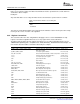
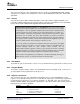
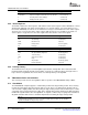
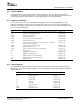
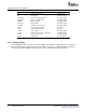
Table Of Contents
- Table of Contents
- Preface
- 1 Overview
- 2 General Programming Guidelines
- 3 Algorithm Component Model
- 3.1 Interfaces and Modules
- 3.1.1 External Identifiers
- 3.1.2 Naming Conventions
- 3.1.3 Module Initialization and Finalization
- 3.1.4 Module Instance Objects
- 3.1.5 Design-Time Object Creation
- 3.1.6 Run-Time Object Creation and Deletion
- 3.1.7 Module Configuration
- 3.1.8 Example Module
- 3.1.9 Multiple Interface Support
- 3.1.10 Interface Inheritance
- 3.1.11 Summary
- 3.2 Algorithms
- 3.3 Packaging
- 3.1 Interfaces and Modules
- 4 Algorithm Performance Characterization
- 5 DSP-Specific Guidelines
- 6 Use of the DMA Resource
- 6.1 Overview
- 6.2 Algorithm and Framework
- 6.3 Requirements for the Use of the DMA Resource
- 6.4 Logical Channel
- 6.5 Data Transfer Properties
- 6.6 Data Transfer Synchronization
- 6.7 Abstract Interface
- 6.8 Resource Characterization
- 6.9 Runtime APIs
- 6.10 Strong Ordering of DMA Transfer Requests
- 6.11 Submitting DMA Transfer Requests
- 6.12 Device Independent DMA Optimization Guideline
- 6.13 C6xxx Specific DMA Rules and Guidelines
- 6.14 C55x Specific DMA Rules and Guidelines
- 6.15 Inter-Algorithm Synchronization
- A Rules and Guidelines
- B Core Run-Time APIs
- C Bibliography
- D Glossary

www.ti.com
5.7.5 Interrupt Latency
TMS320C28x Rules and Guidelines
ST1 Field Name Use Type
ARP Auxiliary register pointer Scratch (local)
XF XF pin status Read Only (global)
M0M1MAP M0 and M1 mapping mode bit Read Only (global)
OBJMODE Object compatibility mode Read Only (global)
AMODE Address mode bit Read Only (global)
IDLESTAT IDLE status bit Read Only (glogal)
EALLOW Emulation access enable bit Read Only (global)
LOOP Loop instruction status bit Scratch (local)
SPA Stack pointer alignment bit Init (local)
VMAP Vector map bit Read Only (global)
PAGE0 PAGE0 addressing mode configuration Read Only (global)
DBGM Debug enable mask bit Read Only (global)
INTM Interrupt mode Preserve (global)
The TMS320C28x CPU has only one non-interruptible loop instruction, namely RPT. Once started, the
RPT instruction blocks interrupts until the entire number of repeats are completed. Thus, the length of
these loops can have significant effect on the worst case interrupt latency of an algorithm
60 DSP-Specific Guidelines SPRU352G – June 2005 – Revised February 2007
Submit Documentation Feedback